Table of Contents
Advertisement
Quick Links
Extron USA - West
Extron USA - East
Extron Europe
Headquarters
+800.633.9876
+800.3987.6673
+800.633.9876
Inside USA / Canada Only
Inside Europe Only
Inside USA / Canada Only
+1.919.863.1794
+31.33.453.4040
+1.714.491.1500
+1.919.863.1797 FAX
+31.33.453.4050 FAX
+1.714.491.1517 FAX
© 2008 Extron Electronics. All rights reserved.
Extron Asia
Extron Japan
Extron China
Extron Dubai
+800.7339.8766
+81.3.3511.7655
+400.883.1568
+971.4.2991800
Inside Asia Only
+81.3.3511.7656 FAX
Inside China Only
+971.4.2991880 FAX
+65.6383.4400
+86.21.3760.1568
+65.6383.4664 FAX
+86.21.3760.1566 FAX
User's Manual
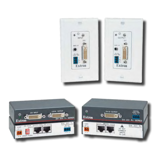
Digital Video Transmitter and Receiver
DVI 201 Tx/Rx
68-1034-02 Rev. B
08 08
Advertisement
Table of Contents

Related Manuals for Extron electronics Digital Video Transmitter and Receiver DVI 201 Rx


Summary of Contents for Extron electronics Digital Video Transmitter and Receiver DVI 201 Rx
- Page 1 Extron USA - West Extron USA - East Extron Europe Extron Asia Extron Japan Headquarters +800.633.9876 +800.3987.6673 +800.7339.8766 +81.3.3511.7655 +800.633.9876 Inside USA / Canada Only Inside Europe Only Inside Asia Only +81.3.3511.7656 FAX Inside USA / Canada Only +1.919.863.1794 +31.33.453.4040 +65.6383.4400 +1.714.491.1500 +1.919.863.1797 FAX...
- Page 2 Safety Instructions • English Warning Power sources • This equipment should be operated only from the power source This symbol is intended to alert the user of important indicated on the product. This equipment is intended to be used with a main power operating and maintenance (servicing) instructions in system with a grounded (neutral) conductor.
- Page 3 安全须知 • 中文 这个符号提示用户该设备用户手册中 有重要的操作和维护说明。 这个符号警告用户该设备机壳内有暴 露的危险电压,有触电危险。 注意 阅读说明书 • 用 户 使 用 该 设 备 前 必 须 阅 读 并 理 解 所 有 安 全 和 使 用 说 明 。 保存说明书 • 用户应保存安全说明书以备将来使 用。 遵守警告 • 用户应遵守产品和用户指南上的所有安 全和操作说明。...
-
Page 4: Table Of Contents
Table of Contents Chapter One • Introduction ... 1-1 About this Manual ... 1-2 About the DVI 201 Transmitters and Receivers TP cable advantages ... 1-4 Control communications ... 1-4 Transmission distance ... 1-4 Features ... 1-5 Chapter Two • Installation and Operation Mounting the Tx/Rx ... - Page 5 Table of Contents, cont’d Appendix A • Reference Information Specifications ...A-2 Part Numbers ...A-6 Transmitter/receiver pair part numbers ...A-6 Included parts ...A-6 Mounting accessories ...A-7 Cables ...A-8 Adapters ...A-8 Decora Template Dimensions ...A-9 All trademarks mentioned in this manual are the properties of their respective owners. DVI 201 Tx/Rx •...
-
Page 6: About This Manual
Introduction About this Manual This manual contains information about the Extron DVI 201 family of Digital Visual Interface (DVI) video transmitters (Tx) and receivers (Rx), including how to install, operate, and configure them. About the DVI 201 Transmitters and Receivers The Extron DVI 201 is a family of DVI transmitters and receivers, in enclosures that support different mounting options. -
Page 7: Tp Cable Advantages
Introduction, cont’d In this manual, the terms "DVI 201," "DVI 201 Tx," "DVI 201 Rx," "transmitter," and "receiver" refer to the applicable unit(s) in either form factor, unless otherwise specified. TP cable advantages Twisted pair cable is much smaller, lighter, more flexible, and less expensive than coaxial or DVI cable. - Page 8 Introduction, cont’d DVI 201 Tx/Rx Chapter Two Installation and Operation Mounting the Tx/Rx Connections Operation Technical Points for Digital Video and Content Protection Encryption Troubleshooting Application Examples DVI 201 Tx/Rx • Introduction...
-
Page 9: Mounting The Tx/Rx
Installation and Operation Mounting the Tx/Rx Installation and service must be performed by authorized personnel only. Non-Decora unit mounting The 1" high, quarter rack width DVI 201 (non-Decora) transmitters and receivers can be placed on a tabletop, mounted on a rack shelf, or mounted under a desk or tabletop. The receiver can be mounted on a projector bracket. -
Page 10: Under-Furniture Mounting
Installation and Operation, cont’d 1U Universal Rack Shelf 1/2 Rack Width Front False Faceplate Both front false faceplates use 2 screws. Use 2 mounting holes on opposite corners. Figure 2-2 — Mounting the transmitter or receiver unit on a standard rack shelf Under-furniture mounting The unit can be mounted under a horizontal surface using an optional MBU 125 under-desk mounting kit (part #70-077-01). -
Page 11: Projector Mounting
Installation and Operation, cont’d Loosely attach the mounting brackets to the transmitter or receiver using the four machine screws and washers supplied with the mounting kit. Hold the transmitter or receiver against the inside of the surface through which it will be mounted. Mark the four screw holes on the inside of the surface to which you are mounting the device. - Page 12 Installation and Operation, cont’d The PMK 300 has a hole in the bottom plate that allows the projector pole to be inserted through the center of the plate (figure 2-6), rather than outside of the plate (figure 2-5). To install the PMK 300 in this configuration, slide the bracket up from the bottom of the pole before the projector is installed on the pole.
-
Page 13: Decora Unit Mounting
Installation and Operation, cont’d Assemble the U-bolt and the following parts in the following order (figure 2-8): a. Pass the legs of the U-bolt through the slotted holes on the mount plate flange. b. Place the legs around the projector pole. c. - Page 14 Installation and Operation, cont’d 2.50” [63.5mm] TP Cable (no boot) 1.51” [38.48mm] TP Cable (no boot) Captive Screw Connectors Junction Box 1.85” [47mm] Figure 2-9 — Decora unit depth profile To install a new wall box, perform steps 1 through 9 below. If a suitable wall box is already installed, perform steps 6 through 9 below.
-
Page 15: Final Installation
Installation and Operation, cont’d Final installation After testing and making any adjustments, do the following: At the power outlet, unplug the power supply. One power supply can power both the transmitter and the receiver, so only one unit needs a power supply. Mount the transmitter or receiver into the wall box, and attach the supplied Decora faceplate to the unit, as shown in figure 2-11. - Page 16 Installation and Operation, cont’d DVI 201 Tx Rear Panel DDC ROUTE POWER REMOTE 0.4A MAX SPARE LOCAL DVI 201 A D Tx Rear Panel DVI 201 A D Tx DO NOT CONNECT TO LAN Figure 2-13 — DVI 201 Tx rear panel connectors DVI input connector —...
-
Page 17: Receiver Connections
Installation and Operation, cont’d Connect transmitter output 1 to receiver input 1. Connect transmitter output 2 to receiver input 2. If necessary, test for proper cable connection (output 1 to input 1, output 2 to input 2) as follows: Plug both TP cables into the powered unit. Momentarily connect either of the cables on the opposite end into the unpowered unit‘s “2”... - Page 18 Installation and Operation, cont’d DVI 201 Rx Front Panel RS-232 PASS THRU Tx Rx DVI 201 A D Rx Front Panel OUTPUT AUDIO OUT RS-232 PASS THRU Figure 2-17 — DVI 201 Rx front panel connectors Receiver input connector — Connect one end of the two separate TP cables from the transmitter output connectors (item on page 2-17) to these RJ-45 female connectors.
-
Page 19: Pin Assignments And Wiring
Installation and Operation, cont’d RS-232 connector — Connect a serial communications port to this 3.5 mm, 3-pole captive screw connector for bidirectional RS-232 communication. See "RS-232 connector wiring," on page 2-26, to wire the connector. The RS-232 connector can also transmit one-way modulated infrared (IR) signals. -
Page 20: Power Supply Wiring
Installation and Operation, cont’d Terminating shielded cable The transmitter and receiver pair works with unshielded twisted pair (UTP) or shielded twisted pair (STP) cables; but, to ensure FCC Class A and CE compliance, STP cables are recommended. The Tx/Rx includes four shielded RJ-45 connectors and a length of self-adhesive shielded tape that you can use to make the STP cables that connect the transmitter and receiver. -
Page 21: Rs-232 Connector Wiring
Installation and Operation, cont’d The length of the exposed (stripped) copper wires is important. The ideal length is 3/16" (5 mm). Longer bare wires can short together. Shorter wires are not as secure in the connector and could be pulled out. Do not tin the power supply leads before installing in the connector. -
Page 22: Transmitter Control And Indicator
Installation and Operation, cont’d INPUT AUDIO L+R RS-232 PASS THRU DVI 201 A D Tx Transmitter Front Panel Figure 2-27 — Decora model power indicator DVI 201 Tx/Rx • Installation and Operation 2-28 Transmitter control and indicator Power LED — DVI 201 Tx (non-Decora) —... -
Page 23: Technical Points For Digital Video And Content Protection Encryption
Installation and Operation, cont’d Technical Points for Digital Video and Content Protection Encryption • Digital Visual Interface (DVI) is a digital video format that was created by the computer industry in 1999. • High Definition Multimedia Interface (HDMI multimedia format that was created by the consumer video industry in 2003. -
Page 24: Application Examples
Installation and Operation, cont’d Application Examples Audio conversion Figure 2-28 shows a standard installation with DVI video and an audio input. The DVI 201 A D Tx converts the video input into two proprietary TP outputs. The Tx outputs the audio directly on a captive screw connector. -
Page 25: Specifications
Installation and Operation, cont’d DVI 201 Tx/Rx • Installation and Operation 2-34 DVI 201 Tx/Rx A ppendix A Reference Information Decora Template Dimensions Specifications Part Numbers... -
Page 26: Appendix A • Reference Information Specifications
Reference Information Specifications *Appropriate DVI-D to HDMI cables or adapters are required for HDMI signal input/output. Also, an optional Extron HDMI-to-DVI adapter is required in order to transmit a CEC signal. Video Maximum data rate... 4.95 Gbps (1.65 Gbps per color) Maximum pixel clock ... - Page 27 Reference Information, cont’d Impedance DVI 201 A D Tx... 50 ohms unbalanced, 100 ohms balanced DVI 201 A D Rx... 50 ohms unbalanced Maximum level (Hi-Z) DVI 201 A D Tx... >+16 dBu, balanced or unbalanced at 1% THD+N DVI 201 A D Rx... >+9.8 dBu, unbalanced at 1% THD+N Maximum level (600 ohm) DVI 201 A D Tx...
-
Page 28: Part Numbers
Reference Information, cont’d Part Numbers Transmitter/receiver pair part numbers The Tx/Rx system requires a transmitter/receiver pair. The transmitter and receiver can be purchased as a pair (of the same form factor) or separately (to mix form factors or Decora colors). DVI 201 models DVI 201 Tx/Rx (non-Decora) DVI 201 Tx... -
Page 29: Cables
Reference Information, cont’d Cables Accessories DVID SL/6 DVI-D male-to-male, 6' (1.8 m) cable HDMI M-M/6 HDMI male to male, 6' (1.8 m) HDMI M-DVI-DM/6 HDMI male to DVI-D male, 6' (1.8 m) Adapters Accessories HDMIF-DVIDM HDMI female to DVI-D male adapter HDMIM-DVIDF HDMI male to DVI-D female adapter DVI 201 Tx/Rx •... - Page 30 Reference Information, cont’d DVI 201 Tx/Rx • Reference Information A-10...
Need help?
Do you have a question about the Digital Video Transmitter and Receiver DVI 201 Rx and is the answer not in the manual?
Questions and answers