Table of Contents
Advertisement
Quick Links
Model
WVOC-4HF
IMPORTANT: DO NOT DISCARD THIS MANUAL
This manual is considered to be part of the appliance and is to be given to the OWNER or
MANAGER of the restaurant, or to the person responsible for TRAINING OPERATORS of
this appliance. Additional manuals are available from your WELLS DEALER.
THIS MANUAL MUST BE READ AND UNDERSTOOD BY ALL PERSONS USING OR
INSTALLING THIS APPLIANCE. Contact your WELLS DEALER if you have any
questions concerning installation, operation or maintenance of this equipment.
304964
2M-
p/n
Rev. E
WELLS BLOOMFIELD, LLC
10 Sunnen Dr., St. Louis, MO 63143
telephone: 314-678-6314
fax: 314-781-2714
www.wellsbloomfield.com
4 HOTPLATE COOKTOP
OWNERS MANUAL
WVOC- 4 SERIES
CONVECTION OVEN
and
with
UNIVERSAL
HOOD
MODELS:
WVO4HF
WVO4HS
Includes
INSTALLATION
USE & CARE
EXPLODED VIEW
PARTS LIST
WIRING DIAGRAM
M506
506
12
0214
Advertisement
Table of Contents

Related Manuals for Wells WVO4HF


Summary of Contents for Wells WVO4HF
-
Page 1: Owners Manual
Additional manuals are available from your WELLS DEALER. THIS MANUAL MUST BE READ AND UNDERSTOOD BY ALL PERSONS USING OR INSTALLING THIS APPLIANCE. Contact your WELLS DEALER if you have any questions concerning installation, operation or maintenance of this equipment. -
Page 2: Warranty
The for information and other details concerning warranty. prices charged by Wells Bloomfield for its products are SERVICE POLICY AND PROCEDURE GUIDE and ADDITIONAL WARRANTY EXCLUSIONS Resetting of safety thermostats, circuit breakers, over cleaning schedules, are customer responsibility. -
Page 3: Table Of Contents
PARTS & SERVICE............CUSTOMER SERVICE DATA ........INTRODUCTION Thank You for purchasing this Wells Bloomfield appliance. Proper installation, professional operation and consistent maintenance of this appliance will ensure that it gives you the very best performance and a long, economical service life. -
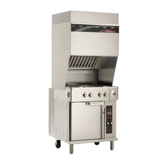
Page 4: Features & Operating Controls
FEATURES & OPERATING CONTROLS Fig. 1 Ventilator Section Features & Operating Controls... - Page 5 FEATURES & OPERATING CONTROLS (continued) VENTILATOR SECTION ITEM DESCRIPTION COMMENT Gives Manufacturer, Model and Serial Number information. NAMEPLATE Also lists electrical specifications. FIRE SUPPRESSION Container for Ansulex™ Low-pH liquid fire suppression liquid. AGENT TANK (1.5 gal.) ADJUSTABLE (FRONT) LEG Allows the unit to be leveled. Allows the unit to be easily positioned by lifting the front of the unit RIGID (REAR) CASTER slightly.
- Page 6 FEATURES & OPERATING CONTROLS (continued) Fig. 2 Ventilator Section Controls & Indicator Lights Fig. 3 Cooktop Section Controls & Indicator Lights Fig. 4 Convection Oven Operating Features & Controls...
- Page 7 FEATURES & OPERATING CONTROLS (continued) Item NO. Description Comments VENTILATOR SECTION CONTROLS POWER SWITCH Energizes blower motor. If, after 10 seconds, proper conditions POWER ON INDICATOR are met, cooktop is energized. CHECK FILTERS ALARM INDICATOR GREEN. Glows when POWER switch is ON. AMBER.
-
Page 8: Precautions & General Information
PRECAUTIONS AND GENERAL INFORMATION NOTE: Fire suppression system and all associated components DANGER must only be serviced by an authorized Ansul® Distributor. All setup, charging, repair and/or adjustment of the fire suppression system must ELECTRIC SHOCK HAZARD be performed by an Authorized Ansul® Distributor ONLY. IMPORTANT: If a remote pull station is installed, both rear casters (9) must be replaced with legs to deter moving the unit. -
Page 9: Agency Listing Information
(i.e. red SERVICE REQUIRED light is on), when the user fails to have the proper replacement pre-filter and/or filter pack on hand. The Ventless Cooking System™ hood is designed as part of a WELLS Fig. 5 Ventilator cooking appliance only. No other use of this product is authorized by the manufacturer or its agents. -
Page 10: Installation
INSTALLATION NOTE: DO NOT discard UNPACKING & INSPECTION the carton or other packing Carefully remove the appliance from the carton. Remove all protective plastic film, packing materials and accessories from the materials until you have inspected the appliance for Appliance before connecting electrical power or otherwise performing hidden damage and tested it any installation procedure. -
Page 11: Electrical Installation
INSTALLATION (continued) SERVICE TECHNICIAN INSTALLATION NOTES IMPORTANT! An Ansul® technician must charge and arm the fire suppression system Verify that this VENTILATOR before the ventilator blower will operate. See page 10. and food cooking equipment installation is in compliance Installation and start up must be performed by an Authorized with the specifications listed Installation Company. - Page 12 In this case, the unit must only be installed with four fixed legs (i.e. remove rear casters and replace with legs). Additional legs may be ordered through an Authorized Wells Service Agency. See page 25. 2. The FIRE SUPPRESSION SYSTEM is comprised of a...
- Page 13 Then lower and seat the assembly lip of the top filter rail. into the top indentation of the lower filter rail. Use only genuine Wells GREASE BAFFLE: If the GREASE BAFFLE is not in place, the CHECK parts and filters, call FILTERS indicator will glow.
- Page 14 INSTALLATION (continued) WARNING GREASE TROUGH AND GREASE CUP INSTALLATION SLIP / FALL 1. Install the GREASE TROUGH into the brackets below the grease baffle. HAzARD SPILLED OIL 2. Install the GREASE CUP on the right side of the unit, directly below the grease trough.
-
Page 15: Operation
OPERATION CAUTION: VENTILATOR OPERATION HOT SURFACE Press the VENTILATOR POWER switch to ON. The green VENTILATOR POWER light will glow and the blower fan will start. Exposed surfaces can be hot After a short time, if all filters are sensed as being in position and to the touch and may cause not clogged, the cooking appliance will be energized. -
Page 16: Suggested Cooking Times
OPERATION (continued) SUGGESTED COOKING TIMES A. CONVECTION OVEN PRODUCT TEMP TIME NUMBER ºF MINUTES OF RACKS BREAD PRODUCTS Hamburger Roll Bread (1 lb loaves) 3 (12 loaves) Roll 5 (60 rolls) Baking Soda Biscuit For best baking results, use rack positions 2, 5 & 8 ( where rack position 1 is the top rack) Baking one pan: use rack 5;... - Page 17 OPERATION (continued) CONVECTION OVEN OPERATING INSTRUCTIONS CAUTION: A. MANUAL COOK MODE HOT SURFACE 1. Set the OVEN POWER SWITCH (C.01) to ON. The OVEN Exposed surfaces POWER ON INDICATOR (C.03) will glow when the switch is ON. can be hot to the touch and may cause burns.
-
Page 18: Cleaning Instructions
OPERATION (continued) CAUTION: C. TEMPERATURE OFFSET MODE HOT SURFACE 1. A user preference offset mode is provided should the user feel the Exposed surfaces can be hot oven cooks too hot or too cold. to the touch and may cause burns. - Page 19 OPERATION (continued) HOTPLATE OPERATING INSTRUCTIONS CAUTION: HOT SURFACE COOKING WITH YOUR HOTPLATE Exposed surfaces can be hot to the touch and may cause burns. 1. Each element is individually controlled by a TEMPERATURE CONTROL (H.01 and H.03). These are infinite switch controls which control based on electrical CAUTION: current draw, not the actual...
- Page 20 CLEANING INSTRUCTIONS CONVECTION OVEN CLEANING INSTRUCTIONS DANGER PRECAUTIONS Turn oven power switch to FAN ELECTRIC SHOCK HAZARD Allow oven to cool FREQUENCY As Noted TOOLS Mild Detergent, Soft Cloth or Sponge Plastic Scouring Pad Spray Bottle Commercial Oven Cleaner/Degreaser DO NOT SPRAY WATER ON OR AROUND DAILY ELECTRICAL EQUIPMENT DO NOT WASH FLOOR NEAR ELECTRICAL...
- Page 21 CLEANING INSTRUCTIONS (continued) HOTPLATE CLEANING INSTRUCTIONS CAUTION: BURN HAzARD PRECAUTIONS Turn oven controls to OFF Turn off both hotplates and Allow hotplates to cool allow to cool before cleaning FREQUENCY Daily CAUTION: ELECTRIC TOOLS Mild Detergent, Soft Cloth or Sponge SHOCK HAzARD Non-abrasive Cleaner, Plastic Scouring Pad DO NOT splash...
- Page 22 CLEANING INSTRUCTIONS (continued) CAUTION: VENTILATOR SECTION CLEANING INSTRUCTIONS ELECTRIC SHOCK HAzARD PREPARATION Disconnect appliance from electric power Disconnect appliance Allow to cool before cleaning from electric power before cleaning. FREQUENCY Weekly TOOLS CAUTION: Warm water and a mild detergent HOT SURFACE Soft clean cloth or sponge Bristle brush Exposed surfaces can be hot...
-
Page 23: Troubleshooting Suggestions
1. Verify that associated temperature control is set to the desired temperature. CONVECTION OVEN 2. Possible internal component damage: Have unit serviced by an CONTROLLER Authorized Wells Service Agency. ERROR CODES F1 Relay closed or relay C. CONVECTION OVEN WILL NOT HEAT See Error Codes diagram at right... -
Page 24: Maintenance Instructions
MAINTENANCE INSTRUCTIONS FAN CLEANING CAUTION: RISK OF PRECAUTIONS: Disconnect power at the circuit breaker. INjURY Allow the oven to cool. Disconnect appliance from electrical power before performing any of these FREQUENCY: Monthly, at a Minimum; or, As Needed procedures. TOOLS: Moist Cloth or Spongs Bristle Brush CAUTION:... - Page 25 MAINTENANCE INSTRUCTIONS (continued) HINGE ADJUSTMENT CAUTION: BURN HAzARD PRECAUTIONS: None Allow appliance to cool FREQUENCY: Monthly, at a Minimum; or, As Needed completely before adjusting. TOOLS: Phillips (+) Screwdriver 7/16” Nut Driver 7/8” and 1-1/8” Wrenches THE FOLLOWING PROCEDURE IS TO BE PERFORMED BY QUALIFIED PERSONNEL ONLY 1.
- Page 26 MAINTENANCE INSTRUCTIONS (continued) D. TEMPERATURE CALIBRATION CAUTION: Hot Surface TOOLS: Digital Pyrometer with Oven Probe, Protective Gloves Exposed surfaces can be hot 1. With the oven empty, clamp the thermocouple sensor in the center to the touch and may cause of the middle rack: burns.
-
Page 27: Maintenance Schedules
MAINTENANCE SCHEDULES USE AND MAINTENANCE 1. 6-MONTH MAINTENANCE (MUST BE PERFORMED BY AN SHALL BE IN ACCORDANCE AUTHORIZED ANSUL® DISTRIBUTOR ONLY): WITH THE STANDARD FOR Inspect and test total operation including FIRE DAMPER and VENTILATION CONTROL all SAFETY INTERLOCKS. AND FIRE PROTECTION OF All FIRE SUPPRESSION SYSTEM actuation components COMMERCIAL COOKING including MANUAL PULL STATION and any REMOTE... - Page 30 ANSUL MATERIAL SAFETY DATA SHEET A N S U L IN C O R P O R AT E D ® M A R IN E T T E , W I 5 4 14 3-2 54 2 ANSULEX Low pH Q U IC K ID E N TIFIE R (In P la n t C o m m o n N a m e ) E m erg e nc y M a n u fac tu re r’s...
- Page 31 ANSULEX Low pH (continued) SECTION 5 - HEALTH HAzARDS Th res h o ld N o ne E s tab lish ed L im it Va lu e : R o u te s o f E n try: Irritan t E ye C o n tac t: S kin C o n ta c t: Irritan t...
- Page 32 ANSUL® FIRE SUPPRESSION SYSTEM COMPONENTS FOR USE ONLY BY AUTHORIZED ref. ADAPTER, QUICK-SEAL 3/8” ANSUL© SERVICE PERSONNEL ANSUL© p/n 77284 Refer to Ansul© part no. 418078-05 ref. NOZZLE 290 R-102 Restaurant Fire Suppression ANSUL© p/n 419342 System Design, Installation, Recharge and Maintenance ref.
-
Page 33: Exploded View & Parts List
EXPLODED VIEW & PARTS LIST COOKTOP SECTION COMPONENTS HEATING ELEMENT, SOLID 240V 2000W 2M-503973 WS-50293 COMPLETE SCREW 8-32 x 3/8 ASSEMBLY (pk 100) 2C-33890 BRACKET, HOLD-DOWN SOLID ELEMENT DD-501451 NUT, 8-32 KEPS Ni 2C-31053 FAN, COOLING 2U-303655 INFINITE SWITCH 240V A CAM 2E-30562 LIGHT, SIGNAL AMBER 2J-30516 Thermal Protector... - Page 34 EXPLODED VIEW & PARTS LIST HOOD SECTION - CABINET COMPONENTS INTERNAL BRACKETS FIRE DAMPER ASSY 280ºF (ref. 2V-301187) LABEL, CONTROL PANEL 2M-502782 GASKET, SILICONE 15-1/4” M3-302772 GASKET, SILICONE 18-1/2” WS-502773 ASSY, FILTER PACK M3-302775 PREFILTER 2I-302579 HOUSING, LIGHT SOCKET 2E-305098 CAGE, BULB, APPLIANCE PRE-FILTER...
- Page 35 EXPLODED VIEW & PARTS LIST HOOD SECTION - ELECTRICAL & VACUUM COMPONENTS FITTING, 1/2” CONDUIT ASSY, BLOWER STRAIGHT 2K-37748X 240V 2U-302584 VACUUM SWITCH 2E-302593 VACUUM SWITCH 2E-302590 VACUUM SWITCH 2E-302592 ASSY, VAC TUBE MANIFOLD N1-302588 VACUUM SWITCH 2E-302591 ref Ansul® 77284 ref Ansul®...
- Page 36 EXPLODED VIEW & PARTS LIST CONVECTION OVEN SECTION - CABINET COMPONENTS SUPPORT, CLIP, RACK OVEN RACK SUPPORT BUSHING, TOP 5F-21375 F6-43889 HINGE 2K-305619 B I N PIN, HINGE 2A-305610 DOOR STRIKER 2C-305616 DOOR LATCH 2C-305615 OVEN RACK 5F-21376 ASSEMBLY, DOOR COMPLETE F6-504444 GUARD, PROX.
- Page 37 EXPLODED VIEW & PARTS LIST CONVECTION OVEN SECTION - ELECTRICAL COMPONENTS ELEMENT, COVER, GASKET 2.5” SPACING INNER F6-43836 CONTACTOR 208/240V 2N-43866UL (208V) 3ø 50a 2E-302789 2N-43800UL (240V) THERMO, ELEMENT, HI-LIMIT 2T-45180 RELAY, BLDG 4” SPACING FIRE ALARM 2E-44514 2N-43872UL (208V) PROBE, TEMP 2N-43783UL (240V) OC-1 2J-304712...
-
Page 38: Wiring Diagram
WIRING DIAGRAM HOOD SECTION... - Page 39 WIRING DIAGRAM CONVECTION OVEN SECTION...
- Page 40 WIRING DIAGRAM HOTPLATE COOKTOP SECTION...
- Page 41 NOTES...
- Page 42 NOTES...
-
Page 43: Parts & Service
Service Dept. phone: (314) 678-6314 fax: (314) 781-2714 NOTE: Ansul® Manual 418087-05 and Wells Bulletin 303331 are intended for use Service Parts Department by authorized Ansul® service personnel only. can supply you with the name Ansul® Manual 418087-05 must be obtained... - Page 44 WELLS BLOOMFIELD, LLC 10 Sunnen Dr., St. Louis, MO 63143 telephone: 314-678-6314 fax: 314-781-2714 www.wellsbloomfield.com...
Need help?
Do you have a question about the WVO4HF and is the answer not in the manual?
Questions and answers