ADDER AdderLink Infinity dual User Manual
Hide thumbs
Also See for AdderLink Infinity dual:
- User manual (52 pages) ,
- User manual (50 pages) ,
- User manual (49 pages)

Related Manuals for ADDER AdderLink Infinity dual


Summary of Contents for ADDER AdderLink Infinity dual
- Page 1 AdderLink Infinity dual User Guide Experts in KVM Extension Connectivity Solutions Solutions...
-
Page 2: Table Of Contents
Contents Introduction Configuration Welcome ........................2 Initial configuration ....................16 AdderLink Infinity dual unit features ...............3 Manual factory reset ..................16 Supplied items .......................4 AdderLink Infinity browser-based configuration utility .......17 Optional extras .....................5 A rough guide to configuring TX and RX units ........18 TX (transmitter) unit configuration ...........18... -
Page 3: Welcome
Introduction Welcome Thank you for choosing AdderLink Infinity dual, otherwise known as ALIF dual (2000 one-to-one configuration The simplest configuration links one RX unit to a single TX unit, either by a direct link or over much series). ALIF dual represents a major advance in the capabilities of digital extenders greater distances via a high speed network. -
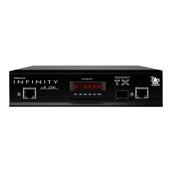
Page 4: Adderlink Infinity Dual Unit Features
ADDeRlINk INfINITy DUAl UNIT feATUReS The ALIF dual units are housed within durable, metallic enclosures with most connectors situated at the rear panel - the Ethernet ports are situated on the front panels. The smart front faces also feature the operation indicators. -
Page 5: Supplied Items
SUPPlIeD ITemS ALIF dual transmitter (2002T) package Power adapter (20W) and country-specific power cord Combined DVI-D and USB Single link DVI-D to DVI-D video cable cable (1.8m) ALIF2002T unit Information wallet containing: Serial null modem cable 2m Four self-adhesive rubber feet 2 x Audio cable 2m Quick start guide (3.5mm stereo jacks) -
Page 6: Optional Extras
oPTIoNAl eXTRAS Single mode fibre SFP module Part number: SFP-SM-LC Please refer to the table in Appendix F information about fibre modules and cables. Two 19” rack-mount brackets and four screws Part numbers: One unit per 1U rack slot: RMK4S Single link DVI-D to DVI-D video cable Two units per 1U rack slot: RMK4D Part number: VSCD1... -
Page 7: Installation
Installation moUNTINg There are two main mounting methods for transmitter and receiver units: • The supplied four self-adhesive rubber feet • Optional rack brackets Connections Rack brackets The optional brackets (plus four screws), allow the units to be secured within a standard rack slot. Note: The ALIF units and their power supplies generate heat when in operation and will become warm to the touch. -
Page 8: Connections
coNNecTIoNS Installation involves linking the ALIF TX unit to various ports on the host computer, while the ALIF RX unit is attached to your peripherals: Click a connection to see details IMPORTANT: When using an AdderLink Infinity Management box to configure ALIF units, it is vital that all ALIF units that you wish to locate and control are set to their factory default settings. -
Page 9: Tx Video Link
Note: When using one very high resolution DVI-D dual link display, use a DVI-D To primary video output port Dual Link cable (such as the supplied Adder part: VSCD3) to connect the primary video port of the computer system to the DVI-D-1 connector of the ALIF dual. A dual link cable must also be used at the RX unit. -
Page 10: Tx Audio Links
TX audio links TX USB link ALIF dual units support two way stereo ALIF dual units act as USB 2.0 hubs and so digital sound so that you can use a remote can provide four sockets at the RX unit microphone as well as speakers. -
Page 11: Tx Aux Port
TX AUX port TX power in The AUX port is an RS232 serial port Each ALIF dual unit is supplied with a that allows extension of RS232 signals up power adapter and country-specific power to a baud rate of 115200. The port has cord. -
Page 12: Tx/Rx High Speed Links
TX/RX high speed links ALIF dual units can be either connected directly to each other or via a high speed network. The connections can be copper-based Gigabit Ethernet as well as Fibre Channel over Ethernet (FCoE). These can be used in parallel to provide up to 2 Gigabit connections speeds. -
Page 13: Tx/Rx Management Port
TX/RX Management port The Management port on each ALIF dual unit provides a consistent method to gain access to the internal configuration utility of each ALIF dual. Although the configuration utility is accessible via the System (Gigabit Ethernet) port and also the Teaming port; if the ALIF dual units are being used in a point-to-point arrangement, then it would be necessary to temporarily reconnect each unit to a network in order to make configuration changes. -
Page 14: Rx Video Display
To secondary video display Note: When using one very high resolution DVI-D dual link display, use a DVI-D Dual Link cable (such as Adder part: VSCD3) to connect the video display to the DVI-D-1 connector To primary video display of the RX unit. A dual link cable must also be used at the TX unit. -
Page 15: Rx Microphone & Speakers
• If a device cannot be made to work, please contact Adder technical support as a special entry within the advanced configuration may solve it. -
Page 16: Rx Aux Port
RX AUX port RX power in The AUX port is an RS232 serial port Each ALIF unit is supplied with an that allows extension of RS232 signals up appropriate power adapter. When all to a baud rate of 115200. The port has other connections have been made, software flow control, but no hardware connect and switch on the power... -
Page 17: Configuration
Configuration INITIAl coNfIgURATIoN Manual factory reset ALIF units are designed to be as flexible as possible and this principle extends also to A factory reset returns an ALIF TX or RX unit to its default configuration. You can their configuration. perform factory resets using the AdderLink Infinity browser-based configuration utility or by using this direct manual method. -
Page 18: Adderlink Infinity Browser-Based Configuration Utility
AdderLink Infinity browser-based configuration utility The browser-based configuration utility within all TX and RX units requires a network To access the browser-based configuration utility connection between the ALIF dual unit and a computer on the same network. The 1 Temporarily connect the ALIF dual unit and your computer, as discussed left. configuration utility allows you to perform many important functions. -
Page 19: A Rough Guide To Configuring Tx And Rx Units
A rough guide to configuring TX and RX units TX (transmitter) unit configuration Optimizing the TX video signal In the ALIF dual system, the majority of configuration settings are dictated by the units. Therefore, the local TX unit setup (using its browser-based configuration utility) is Note: Where the ALIF dual system is linked via two Gigabit links with sufficient available usually concerned only with three main factors: Its IP address details, the data streams bandwidth, there should be no need to alter the default settings on this page. -
Page 20: Rx (Receiver) Unit Configuration
RX (receiver) unit configuration In the ALIF dual system, it is the RX unit (receiver) that determines where and how data signals are sent (and received) by the unit. Although numerous topologies (one- to-one, one-to-many, many-to-one, etc.) are made possible by the ALIF system, they are all dependent on two underlying modes of operation: either Unicast or Multicast transmission. - Page 21 5 In the Target Transmitter Unit Settings section, you need to enter the System port and Teaming The two Video and the single Audio Multicast sub-sections are configured in exactly port IP addresses for the TX unit that will be supplying the video, audio, USB and serial data the same way: streams.
-
Page 22: Performing An Upgrade
See right for details. To upgrade a single unit via network link Option switch 2 is reserved and must remain in the OFF (up) position for normal 1 Download the latest upgrade file from the Adder Technology website. operation. Note: There are separate upgrade files for TX and RX units. -
Page 23: Operation
Operation In operation, many ALIF dual installations require no intervention once configured. The TX and RX units take care of all connection control behind the scenes so that you can continue to work unhindered. fRoNT PANel INDIcAToRS The six front panel indicators on each unit provide a useful guide to operation: Indicators These six indicators clearly show the key aspects of operation: •... -
Page 24: Further Information
- Receiver (TX) unit configuration pages • Online solutions and updates – www.adder.com/support • Appendix C - Tips for success when networking ALIF units Check the Support section of the adder.com website for the latest solutions and firmware updates. • Appendix D - Troubleshooting •... -
Page 25: Appendix A - Transmitter (Tx) Unit Configuration Pages
APPeNDIX A - Transmitter (TX) unit configuration pages This section covers the browser-based configuration utility for the AdderLink Infinity TX (transmitter) unit. The TX utility has ten pages, titled as follows: • System Configuration • System Messages • Video Configuration •... -
Page 26: Tx System Configuration
TX System Configuration Unit Name Name details that you can alter to distinguish this unit from all others. The name entered here will be read by A.I.M. units (if used) for administration purposes. Unit Description Allows you to optionally add a description of the unit, such as its location. Useful when many ALIF units are being used. -
Page 27: Tx Video Configuration
TX Video Configuration Peak bandwidth limiter percentage The TX unit will employ a ‘best effort’ strategy in sending video and other data over the IP network. This means it will use as much of the available network bandwidth as necessary to achieve optimal data quality, although typically the TX unit will use considerably less than the maximum available. - Page 28 TX USB Settings Enable Dummy Boot Keyboard When ticked, the TX unit reports a virtual dummy boot keyboard to the attached PC to ensure that a keyboard is always reported when the PC boots up. The dummy boot keyboard uses one of the 13 USB endpoints, therefore if all 13 endpoints are required elsewhere for USB devices (or a KVM switch only supports two HID devices) then it can be disabled by deselecting this option.
-
Page 29: Tx System Messages
Enable AIM Control Click this button to allow an A.I.M. (Adder Infinity Manager) box to take control of this TX. When the button is clicked, the TX unit will be rebooted to allow the A.I.M. box to discover and control it. -
Page 30: Tx Firmware Upgrade
TX Statistics Enable collection of bandwidth statistics The ALIF dual unit can record data transfer statistics from the System port and plot them on a graph for troubleshooting and optimization purposes. When you enable this option, you will first be presented with a pop up from which you can choose which aspects you would like to graph: Data throughput, various packet rates and/or frame rates. - Page 31 TX About About This page displays key information about the TX unit that may be requested by Adder Technical Support. To get here Connect your computer to the Management port on the left side of the front panel. 2 Run a web browser and enter the IP address of the Management port: http://192.168.1.42...
-
Page 32: Appendix B - Receiver (Rx) Unit Configuration Pages
APPeNDIX B - Receiver (RX) unit configuration pages This section covers the browser-based configuration utility for the AdderLink Infinity RX (receiver) unit. The RX utility has nine pages, titled as follows: • System Configuration • Statistics • USB Settings • Firmware Upgrade •... - Page 33 RX System Configuration (1 of 2) Unit Name Name details that you can alter to distinguish this unit from all others. The name entered here will be read by A.I.M. units (if used) for administration purposes. Unit Description Allows you to add a description of the unit, such as its location. Useful when many ALIF units are being used. System port This section determines the IP address, netmask and gateway details for the main Gigabit Ethernet port located on the right side of the front panel.
- Page 34 RX System Configuration (2 of 2) Target Transmitter Unit Settings This section is where you configure the IP address details of the ALIF dual transmitter(s) that this receiver will connect with. For installations where the Teaming port (using an optional SFP module) is used to link units as well as the main (Gigabit Ethernet) System port, this section also allows you to determine which peripherals should use the second link.
- Page 35 Isochronous Endpoint OSD Alerts The AdderLink Infinity dual USB system does not support Isochronous USB. When enabled, this option will alert the user when an Isochronous USB device is connected. Enable Isochronous Endpoint Attach When enabled, this option will allow for an exchange of control information with an Isochronous device.
- Page 36 RX Security Encryption This setting allows you to apply encryption to the USB and control data passed across the link. Note that video data is never encrypted. Secure Web pages with password When ticked, this option enables https security so that the configuration pages are only accessible to the admin user with a password.
-
Page 37: Rx System Messages
Enable AIM Control Click this button to allow an A.I.M. (Adder Infinity Manager) box to take control of this RX. When the button is clicked, the RX unit will be rebooted to allow the A.I.M. box to discover and control it. -
Page 38: Rx Firmware Upgrade
RX Statistics Enable collection of bandwidth statistics The ALIF dual unit can record data transfer statistics from the System port and plot them on a graph for troubleshooting and optimization purposes. When you enable this option, you will first be presented with a pop up from which you can choose which aspects you would like to graph: Data throughput, various packet rates and/or frame rates. - Page 39 RX About About This page displays key information about the RX unit that may be requested by Adder Technical Support. To get here Connect your computer to the Management port on the left side of the front panel. 2 Run a web browser and enter the IP address of the Management port: http://192.168.1.42...
-
Page 40: Appendix C - Tips For Success When Networking Alif Units
L2 and the L3. Typically 10GB and 20GB, respectively for 48 port L2 • Cisco 6500 switches. For the latest list of switches known to work continued with ALIF and setup instructions for them, please go to www.adder.com... - Page 41 Configuring the switches and devices The layout is vital but so too is the configuration: • Enable IGMP Snooping on all L2 switches. • Ensure that IGMP Fast-Leave is enabled on all switches with ALIF units connected directly to them. •...
-
Page 42: Appendix D - Troubleshooting
APPeNDIX D - Troubleshooting Problem: The video image of the ALIF receiver shows horizontal lines across Remedies: the screen. • Ensure that IGMP snooping is enabled on all switches within the subnet. This issue is known as Blinding because the resulting video image looks as though you’re •... - Page 43 You can easily tell whether portfast is enabled on a switch that is running STP: When Use the Adder utility for Mac’s – Contact technical support. you plug the link cable from a working ALIF unit into the switch port, check how long •...
-
Page 44: Appendix E - Glossary
APPeNDIX e - Glossary Internet Group Management Protocol IgmP Snooping Jumbo frames (Jumbo packets) Where an ALIF transmitter is required to stream video to The IGMP messages are effective but only operate at Since its commercial introduction in 1980, the Ethernet two or more receivers, multicasting is the method used. - Page 45 Spanning Tree Protocol (STP) ALIF transmitter video settings In order to build a robust network, it is necessary Each ALIF transmitter includes controls to help you to include certain levels of redundancy within the customize how video data is transmitted. When configured interconnections between switches.
- Page 46 Forwarding modes In essence, the job of a layer 2 switch is to transfer as So which one to choose? The Cut-through method has the So why are Layer 2 and Layer 3 of particular importance fast as possible, data packets arriving at one port out to least latency so is usually the best to use with AdderLink when discussing AdderLink Infinity? Because the successful another port as determined by the destination address.
-
Page 47: Appendix F - Cable Pinouts, Video Modes And General Specifications
APPeNDIX f - Cable pinouts, video modes and general specifications RS232 ‘null-modem’ cable pin-out General specifications Casing (w x h x d): 198mm (7.92”) x 44mm (1.76”) x 145mm (5.7”) 9pin D-type 9pin D-type Construction: 1U compact case, robust metal design female female Weight:... -
Page 48: Appendix G - Fibre Modules And Cables
To suit your installation layout, two fibre modules are available for the ALIF dual units to suit various fibre optic cables. The specifications for all are summarized in the table below: Fibre Type Fibre size Fibre Type Coding Distance Adder part Conn. number for color type Normal Military Suggested Print... -
Page 49: Appendix H - Additional Features
Unfortunately dithering is an issue for KVM extenders automatic switching method which will revert back to RLE when an AdderLink Infinity such as AdderLink Infinity dual because it makes the image appear to be changing all the receiver is connected to the AdderLink Infinity dual. -
Page 50: Warranty
• No user serviceable parts within power adapter - do not dismantle. Adder will replace or repair it free of charge. No liability can be accepted for damage due • Plug the power adapter into a socket outlet close to the module that it is powering. -
Page 51: Radio Frequency Energy
RADIo fReqUeNcy eNeRgy A Category 5 (or better) twisted pair cable must be used to connect the units in order to maintain compliance with radio frequency energy emission regulations and ensure a suitably high level of immunity to electromagnetic disturbances. All other interface cables used with this equipment must be shielded in order to maintain compliance with radio frequency energy emission regulations and ensure a suitably high level of immunity to electromagnetic disturbances. - Page 52 Web: www.adder.com Contact: www.adder.com/contact-details Support: forum.adder.com © 2013 Adder Technology Limited All trademarks are acknowledged. www.ctxd.com Documentation by: Part No. MAN-ALIF2000 • Release 3.0a...
-
Page 53: Index
Index Active Copper 11 Dimensions 46 Magic Eye 26,48 Safety information 49 Management port 2,3 SFP module 11 Adaptive 45 Display cloning 33 AFZ 48 Dithering 48 RX settings 32 Snooping 43 Anti-dither support 48 TX settings 25 Spanning Tree Protocol 44 Multicast Specifications 46 Factory reset 16...
Need help?
Do you have a question about the AdderLink Infinity dual and is the answer not in the manual?
Questions and answers