ADDER AdderLink Infinity User Manual
Hide thumbs
Also See for AdderLink Infinity:
- User manual (53 pages) ,
- User manual (61 pages) ,
- User manual (52 pages)
Table of Contents
Advertisement
Quick Links
Download this manual
See also:
User Manual
Advertisement
Table of Contents

Related Manuals for ADDER AdderLink Infinity


Summary of Contents for ADDER AdderLink Infinity
- Page 1 AdderLink Infinity User Guide Experts in KVM Extension Connectivity Solutions Solutions...
-
Page 2: Table Of Contents
Initial configuration ....................15 AdderLink Infinity unit features ................3 Manual factory reset ..................15 Supplied items .......................4 AdderLink Infinity browser-based configuration utility .......16 Optional extras .....................5 A rough guide to configuring TX and RX units ........17 TX (transmitter) unit configuration ...........17 Installation RX (receiver) unit configuration ............18... -
Page 3: Welcome
Introduction Welcome Thank you for choosing AdderLink Infinity, otherwise known as ALIF or ALIF1000. ALIF one-to-one configuration The simplest configuration links one RX unit to a single TX unit, either by a represents a major advance in the capabilities of digital extenders and switches. By direct link or over much greater distances via a Gigabit Ethernet network. -
Page 4: Adderlink Infinity Unit Features
Adderlink infinity unit feAtures The ALIF units are housed within durable, metallic enclosures with most connectors situated at the rear panel - the Ethernet ports are situated on the front panels. The smart front faces also feature the operation indicators. -
Page 5: Supplied Items
suPPlied items ALIF transmitter (1000T) package Power adapter (12.5W) and country-specific power cord d e rL in k Combined DVI-D and USB cable (1.8m) ALIF1000T unit w .a er .c Information wallet containing: Four self-adhesive rubber feet Serial null modem cable 2m Quick start guide 2 x Audio cable 2m Safety document... -
Page 6: Optional Extras
oPtionAl eXtrAs Two 19” rack-mount brackets and four screws Part numbers: One unit per 1U rack slot: RMK4S Single link DVI-D to DVI-D video cable Two units per 1U rack slot: RMK4D Part number: VSCD1 Combined dual link DVI-D and USB (USB type A to B) cable Part numbers: VSCD3 (1.8m length) VSCD4 (5m length) Power adapter (12.5W) and... -
Page 7: Installation
Installation mounting There are two main mounting methods for transmitter and receiver units: • The supplied four self-adhesive rubber feet • Optional rack brackets Connections Rack brackets The optional brackets (plus four screws), allow the units to be secured within a standard rack slot. Note: The ALIF units and their power supplies generate heat when in operation and will become warm to the touch. -
Page 8: Connections
ALIF RX unit is attached to your peripherals: Click a connection to see details IMPORTANT: When using an AdderLink Infinity Management box to configure ALIF units, it is vital that all ALIF units that you wish to locate and control are set to their factory default settings. -
Page 9: Tx Video Link
tX video link TX audio links ALIF units support a single high resolution ALIF units support two way stereo digital DVI-D digital video display at pixel clocks sound so that you can use a remote up to 165MHz (equating to an example microphone as well as speakers. -
Page 10: Tx Usb Link
TX USB link TX AUX port ALIF units act as USB 2.0 hubs and so can The AUX port is an RS232 serial port provide four sockets at the RX unit with that allows extension of RS232 signals up only a single connection at the TX unit. to a baud rate of 115200. -
Page 11: Tx Power In
TX power in Each ALIF unit is supplied with an appropriate power adapter. When all other connections have been made, connect and switch on the power adapter unit. To apply power in 1 Attach the output lead from the power adapter to the socket on the rear panel of the unit. -
Page 12: Tx/Rx Network Link
TX/RX network link ALIF units can be either connected directly to each other or via a Gigabit Ethernet network. For direct links via Ethernet cable, the length of cable should not exceed 100 metres (328 feet). Network cables used for connections may be category 5, 5e, 6 or 7 twisted-pair cable. ALIF TX units have an autosensing capability on their network interfaces, so for direct point- to-point connections, no ‘crossover’... -
Page 13: Rx Video Display
RX video display RX microphone & speakers ALIF units support a single high The ALIF unit can support a microphone resolution DVI-D digital video display at as well as speakers providing the pixel clocks up to 165MHz (equating to necessary connections have been made an example display mode of 1920 x 1200 between the ALIF TX unit and the host at 60Hz refresh). -
Page 14: Rx Usb Devices
RX AUX port RX USB devices The AUX port is an RS232 serial port The ALIF RX unit has four USB ports that allows extension of RS232 signals up to which peripherals may be connected. to a baud rate of 115200. The port has The ports are interchangeable. -
Page 15: Rx Power In
RX power in Each ALIF unit is supplied with an appropriate power adapter. When all other connections have been made, connect and switch on the power adapter unit. To apply power in 1 Attach the output lead from the power adapter to the socket on the rear panel of the unit. -
Page 16: Configuration
ALIF units. • Configuring ALIF units collectively - The AdderLink Infinity Management (A.I.M.) server allows you to configure, control and coordinate any number of ALIF transmitters and receivers from a single application. -
Page 17: Adderlink Infinity Browser-Based Configuration Utility
AdderLink Infinity browser-based configuration utility The browser-based configuration utility within all TX and RX units requires a network To access the browser-based configuration utility connection between the ALIF unit and a computer on the same network. The 1 Temporarily connect the ALIF unit and a computer via a network, as discussed configuration utility allows you to perform all of the following functions: opposite. -
Page 18: A Rough Guide To Configuring Tx And Rx Units
A rough guide to configuring TX and RX units TX (transmitter) unit configuration Optimizing the TX video signal In the ALIF system, the majority of configuration settings are dictated by the units. Therefore, the local TX unit setup (using its browser-based configuration utility) is usually Note: Where the ALIF system is connected to a Gigabit Ethernet network with sufficient available concerned only with three main factors: Its IP address details, the data streams to enable/ bandwidth, there should be no need to alter the default settings on this page. -
Page 19: Rx (Receiver) Unit Configuration
RX (receiver) unit configuration In the ALIF system, it is the RX unit (receiver) that determines where and how data signals are sent (and received) by the unit. Although numerous topologies (one- to-one, one-to-many, many-to-one, etc.) are made possible by the ALIF system, they are all dependent on two underlying modes of operation: either Unicast or Multicast transmission. - Page 20 7 Most often the video, audio, USB and serial data streams are supplied by the same TX 9 For installations that require multiple RX units to receive the same feeds, for either unit, so a single primary (and optional secondary) IP address(es) can be used. However, it video or audio or both, then you need to configure the Multicast Settings section.
-
Page 21: Performing An Upgrade
ALIF units are flash upgradeable using the method outlined here. However, for larger A pair of Options switches are located on the rear panel of every ALIF unit. installations we recommend that you use the AdderLink Infinity Manager (A.I.M.) Switch 1 - firmware image select to upgrade multiple ALIF units. -
Page 22: Operation
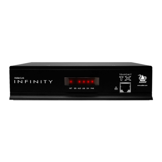
Operation In operation, many ALIF installations require no intervention once configured. The TX and RX units take care of all connection control behind the scenes so that you can continue to work unhindered. front PAnel indicAtors The six front panel indicators on each unit provide a useful guide to operation: Indicators These six indicators clearly show the key aspects of operation: •... -
Page 23: Further Information
Further information getting AssistAnce This chapter contains a variety of information, including the following: If you are still experiencing problems after checking the information contained within this • Getting assistance - see right guide, then we provide a number of other solutions: •... -
Page 24: Appendix A - Transmitter (Tx) Unit Configuration Pages
APPendiX A - Transmitter (TX) unit configuration pages This section covers the browser-based configuration utility for the AdderLink Infinity TX (transmitter) unit. The TX utility has ten pages, titled as follows: • System Configuration • System Messages • Video Configuration •... - Page 25 Click the Refresh Thumbnail button to update. To get here 1 If not already connected, temporarily connect the AdderLink Infinity unit and a PC via a network. 2 Run a web browser and enter the IP address of the TX unit. Default: http://169.254.1.33...
- Page 26 Use Default DDC and Choose Default DDC When the Use Default DDC option is unticked, AdderLink Infinity will use the EDID that is reported by the monitor connected to the receiver unit. However, if you tick the Use Default DDC option, you can then select from a range of preset video resolutions from the Choose Default DDC drop down box.
- Page 27 To get here 1 If not already connected, temporarily connect the AdderLink Infinity unit and a PC via a network. 2 Run a web browser and enter the IP address of the TX unit. Default: http://169.254.1.33...
- Page 28 Click to save and implement any changes that you make. To get here 1 If not already connected, temporarily connect the AdderLink Infinity unit and a PC via a network. 2 Run a web browser and enter the IP address of the TX unit. Default: http://169.254.1.33...
- Page 29 To get here 1 If not already connected, temporarily connect the AdderLink Infinity unit and a PC via a network. 2 Run a web browser and enter the IP address of the TX unit. Default: http://169.254.1.33 If the address is unknown, perform a manual factory reset.
- Page 30 This page displays key information about the TX unit that may be requested by Adder Technical Support. To get here 1 If not already connected, temporarily connect the AdderLink Infinity unit and a PC via a network. 2 Run a web browser and enter the IP address of the TX unit. Default: http://169.254.1.33...
-
Page 31: Appendix B - Receiver (Rx) Unit Configuration Pages
APPendiX B - Receiver (RX) unit configuration pages This section covers the browser-based configuration utility for the AdderLink Infinity RX (receiver) unit. The RX utility has nine pages, titled as follows: • System Configuration • Statistics • USB Settings •... - Page 32 To get here 1 If not already connected, temporarily connect the AdderLink Infinity unit and a PC via a network. 2 Run a web browser and enter the IP address of the RX unit. Default: http://169.254.1.32 If the address is unknown, perform a manual factory reset.
- Page 33 When enabled, this option restricts supported USB devices to keyboards and mice only. The use of memory sticks and other devices is disabled. Isochronous Endpoint OSD Alerts The AdderLink Infinity USB system does not support Isochronous USB. When enabled, this option will alert the user when an Isochronous USB device is connected. Enable Isochronous Endpoint Attach When enabled, this option will allow for an exchange of control information with an Isochronous device.
- Page 34 To get here 1 If not already connected, temporarily connect the AdderLink Infinity unit and a PC via a network. 2 Run a web browser and enter the IP address of the RX unit. Default: http://169.254.1.32...
- Page 35 Click to save and implement any changes that you make. To get here 1 If not already connected, temporarily connect the AdderLink Infinity unit and a PC via a network. 2 Run a web browser and enter the IP address of the RX unit. Default: http://169.254.1.32...
- Page 36 To get here 1 If not already connected, temporarily connect the AdderLink Infinity unit and a PC via a network. 2 Run a web browser and enter the IP address of the RX unit. Default: http://169.254.1.32 If the address is unknown, perform a manual factory reset.
- Page 37 This page displays key information about the RX unit that may be requested by Adder Technical Support. To get here 1 If not already connected, temporarily connect the AdderLink Infinity unit and a PC via a network. 2 Run a web browser and enter the IP address of the RX unit. Default: http://169.254.1.32...
-
Page 38: Appendix C - Tips For Success When Networking Alif Units
APPendiX c - Tips for success when networking ALIF units Creating an efficient network layout ALIF units use multiple strategies to minimize the amount of data that they send across networks. However, data overheads can be quite high, particularly when very Network layout is vital. - Page 39 Configuring the switches and devices The layout is vital but so too is the configuration: • Enable IGMP Snooping on all L2 switches. • Ensure that IGMP Fast-Leave is enabled on all switches with ALIF units connected directly to them. •...
-
Page 40: Appendix D - Troubleshooting
APPendiX d - Troubleshooting Problem: The video image of the ALIF receiver shows horizontal lines across Remedies: the screen. • Ensure that IGMP snooping is enabled on all switches within the subnet. This issue is known as Blinding because the resulting video image looks as though you’re •... - Page 41 Problem: The mouse pointer of the ALIF receiver is slow or sluggish when Problem: The audio output of the ALIF receiver sounds like a scratched re- moved across the screen. cord. This issue is often related to either using dithering on the video output of one or more This issue is called Audio crackle and is a symptom of the same problem that produces transmitting computers or using VGA-to-DVI video converters.
-
Page 42: Appendix E - Glossary
AdderLink Infinity units make use of IGMPv2 when a full checking procedure. Where multiple units are support them. performing multicasts to ensure that no unnecessary regularly joining and leaving multicasts, this can speed up congestion is caused. - Page 43 Spanning Tree Protocol (STP) ALIF transmitter video settings In order to build a robust network, it is necessary Each ALIF transmitter includes controls to help you to include certain levels of redundancy within the customize how video data is transmitted. When configured interconnections between switches.
- Page 44 AdderLink when discussing AdderLink Infinity? Because the successful another port as determined by the destination address. Infinity units. However, if the network components and/...
-
Page 45: Appendix F - Cable Pinouts, Video Modes And General Specifications
APPendiX f - Cable pinouts, video modes and general specifications RS232 ‘null-modem’ cable pin-out General specifications Casing (w x h x d): 198mm (7.92”) x 44mm (1.76”) x 120mm (4.8”) 9pin D-type 9pin D-type Construction: 1U compact case, robust metal design female female Weight:... -
Page 46: Warranty
WArrAnty • For use in dry, oil free indoor environments only. Adder Technology Ltd warrants that this product shall be free from defects in workmanship and materials for a period of two years from the date of original purchase. • Warning - live parts contained within power adapter. -
Page 47: Radio Frequency Energy
rAdio frequency energy A Category 5 (or better) twisted pair cable must be used to connect the units in order to maintain compliance with radio frequency energy emission regulations and ensure a suitably high level of immunity to electromagnetic disturbances. All other interface cables used with this equipment must be shielded in order to maintain compliance with radio frequency energy emission regulations and ensure a suitably high level of immunity to electromagnetic disturbances. - Page 48 Web: www.adder.com Contact: www.adder.com/contact-details Support: forum.adder.com © 2013 Adder Technology Limited All trademarks are acknowledged. www.ctxd.com Documentation by: Part No. MAN-ALIF1000 • Release 3.0a...
-
Page 49: Index
Index Adaptive 43 Factory reset 15 Optimization Upgrade statistics for 28,35 firmware 20 Fast-Leave 41 Firmware Options switches 20 Use ETH2 Background Refresh 42 upgrade 20 OSI model 43 setting 18,19,31 Bracket Forwarding modes 43 rack mount 6 Fragment-free 43 Peak Bandwidth Limiter 42 Video Brackets...
Need help?
Do you have a question about the AdderLink Infinity and is the answer not in the manual?
Questions and answers