Table of Contents
Advertisement
Quick Links
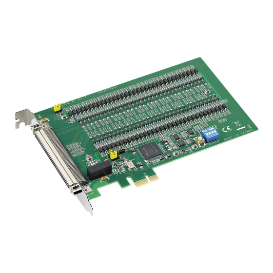
PCI-1752/54/56
Unpacking
The PCI-1752/54/56 package should contain the
following items:
þ
PCI-1752/54/56 card
þ
Companion CD-ROM disc
þ
User's Manual
þ
Quick Start
Driver Installation
Step 1: Insert the companion disc into your CD-
ROM drive.
Step 2: The Setup Program will be launched
automatically, and you'll see the
following Setup Screen.
Select the DLL Drivers installation
option. (If autoplay is not enabled, please
use Windows Explorer or Windows Run
command to execute setup.exe on CD-
ROM).
Step 3: Select the Windows 95/98 or Windows
NT option according to your operating
system.
Step 4: Follow the installation instructions step
by step to complete your DLL driver
setup.
Quick Start
Hardware Installation
Step 1: Turn off your computer and unplug the
power cord and cables
Step 2: Remove the cover of your computer
Step 3: Remove the slot cover on the back panel
of your computer
Step 4: Touch the metal part of your computer
chassis to discharge static electricity on
your body
Step 5: Adjust DIP switch SW1 on board ti set
the card's board ID.
Step 6: Insert the PCI-1752/54/56 card into a
PCI slot. Hold the card only by its edges
and carefully align it with the slot, then
insert the card firmly into place. Use of
excessive force must be avoided
otherwise the card might be damaged.
Step 7: Fasten the bracket of the PCI card on
the back panel rail of the computer with
screws
Step 8: Connect appropriate accessories (100-
pin cable, wiring terminals, etc., if
necessary) to the PCI card.
Step 9: Replace the cover of your computer
chassis. Re-connect the cables you
removed in step 2.
Step10:Plug in the power cord and turn on the
computer
Verifying your Installation
w Access the Device Manager through the
Control Panel/System/Device Manager. On the
Device Manager tab of the System Property
sheet, you can see the Device Name of the
PCI-1752/54/56 listed on it.
Advertisement
Table of Contents


Need help?
Do you have a question about the PCI-1752 and is the answer not in the manual?
Questions and answers