Table of Contents
Advertisement
Quick Links
Advertisement
Table of Contents

Related Manuals for Advantech PCI-1715U


Summary of Contents for Advantech PCI-1715U
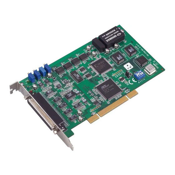
- Page 1 PCI-1715U 32-ch Isolated Analog Input Card User Manual...
- Page 2 No part of this man- ual may be reproduced, copied, translated or transmitted in any form or by any means without the prior written permission of Advantech Co., Ltd. Information provided in this manual is intended to be accurate and reli- able.
- Page 3 Product Warranty (2 years) Advantech warrants to you, the original purchaser, that each of its prod- ucts will be free from defects in materials and workmanship for two years from the date of purchase. This warranty does not apply to any products which have been repaired or...
-
Page 4: Declaration Of Conformity
This product has passed the CE test for environmental specifications when shielded cables are used for external wiring. We recommend the use of shielded cables. This kind of cable is available from Advantech. Please contact your local supplier for ordering information. - Page 5 The sound pressure level at the operator's position according to IEC 704- 1:1982 is no more than 70 dB (A). DISCLAIMER: This set of instructions is given according to IEC 704-1. Advantech disclaims all responsibility for the accuracy of any statements contained herein.
- Page 6 CPU card or other cards while the PC is on. Disconnect power before making any configuration changes. The sudden rush of power as you connect a jumper or install a card may damage sensitive electronic components. PCI-1715U User Manual...
-
Page 7: Table Of Contents
Contents Chapter 1 Overview ............2 Introduction ............... 2 Features ................2 Software Overview............2 Chapter 2 Installation ............4 Unpacking ................. 4 Driver Installation ............. 5 Installation Instructions ............. 6 Chapter 3 Signal Connections .......... 8 Overview ................8 I/O Connector .............. - Page 8 PCI-1715U User Manual viii...
- Page 9 Overview...
-
Page 10: Chapter 1 Overview
Chapter 1 Overview 1.1 Introduction The PCI-1715U is a 12-bit 32-channel analog input card for the PCI bus. It provides 32 analog input channels with a sampling rate up to 500k sam- ples/s, 12-bit resolution and isolation protection of 2500 V 1.2 Features... - Page 11 Installation...
-
Page 12: Chapter 2 Installation
Chapter 2 Installation 2.1 Unpacking After receiving your PCI-1715U package, please inspect its contents first. The package should contain the following items: • PCI-1715U Card • Companion CD-ROM (DLL driver included) • User Manual The PCI-1715U card harbors certain electronic components vulnerable to electrostatic discharge (ESD). -
Page 13: Driver Installation
We recommend you install the software driver before installing the PCI- 1715U module, since this will guarantee a smooth installation process. The 32-bit DLL driver Setup program for the PCI-1715U module is included on the companion CD-ROM that is shipped with your module package. -
Page 14: Installation Instructions
Save the screw to secure the interface card retaining bracket. 5. Carefully grasp the upper edge of the PCI-1715U. Align the hole in the retaining bracket with the hole on the expansion slot and align the gold striped edge connector with the expansion slot socket. - Page 15 Signal Connections...
-
Page 16: Chapter 3 Signal Connections
PCI-1715U card via the I/O connector. 3.2 I/O Connector The I/O connector for the PCI-1715U card is a 37-pin D-type connector which you can connect to 37-pin D-type accessories with Advantech's PCL-10137 cable. -
Page 17: Table 3.1:I/O Connector Signal Description
A signal source without a local ground is also called a “floating source”. It is fairly simple to connect a single-ended channel to a floating signal source. In this mode, the PCI-1715U card provides a reference ground for external floating signal sources. -
Page 18: Figure 3.3:Differential Input-Grounded Signal Source
You must therefore reference the signal source to the AIGND. Figure 3-4 shows a differential channel connection between a floating signal source and an input channel on the PCI-1715U card. In this figure, each side of the floating signal source is connected through a resistor to the AIGND. - Page 19 External Trigger Source Connection In addition to pacer triggering, the PCI-1715U card also allows external triggering for A/D conversions. A low-to-high edge coming from EXT_TRG will trigger an A/D conversion on the PCI-1715U board. Note: Please ascertain that turn on your external trigger source and con- nect it to "EXT_TRG"...
-
Page 20: Field Wiring Considerations
3.4 Field Wiring Considerations When you use the PCI-1715U card to acquire outside data, environmental noise can seriously affect the accuracy of your measurements if you don’t provide any protection. The following suggestions will be helpful when running signal wires between signal sources and the PCI-1715U card. - Page 21 Calibration...
-
Page 22: Chapter 4 Calibration
To assist users in the A/D calibra- tion process, we provide one calibration program, ADCAL.EXE, on the PCI-1715U software CD-ROM. The ADCAL.EXE program makes A/D calibrations easy. It leads you through the calibration and setup procedure with a variety of prompts and graphic displays, showing you all of the correct settings and adjustments. -
Page 23: A/D Calibration
The following list shows the function of each VR: Function VR1 A/D full scale (gain) VR2 A/D bipolar offset VR3 A/D unipolar offset VR4 PGIA initial offset TP1 PGIA output 4.3 A/D Calibration Regular and accurate calibration procedures ensure the maximum possi- ble accuracy. - Page 24 A/D Code Mapping Voltage Hex. Dec. Bipolar ± 5V Unipolar 0 to 10V 000h -4.9971V 7FFh 2047 -0.0024V 4.9947V 800h 2048 4.9971V FFFh 4095 +4.9947V 9.9918V PCI-1715U User Manual...
- Page 25 Specifications...
-
Page 26: A.1 Analog Input
Software, onboard Programmable Pacer or External Accuracy INLE: ±1 LSB Monotonicity: 12 bits Offset error: Adjustable to zero Gain Gain error 0.06 0.03 0.05 0.07 0.09 (% FSR) Ch Type S.E./D S.E./D S.E./D D SNR: 68 dB ENOB: 11 bits PCI-1715U User Manual... -
Page 27: General
A.2 General I/O Connector Type DSub-37 female Dimensions 175 × 100 mm (6.9" × 3.9") Power Consumption Typical +5 V @ 500 mA Max. +5 V @ 700 mA Temperature Operation 0~+60°C (32~158°F) (refer to IEC 68-2-1,2) Storage -20~+85°C (-4~185°F) Relative Humidity 5~95%RH non-condensing (refer to IEC 68-2-3) - Page 28 PCI-1715U User Manual...
Need help?
Do you have a question about the PCI-1715U and is the answer not in the manual?
Questions and answers