
Related Manuals for Advantech AIMB-567


Summary of Contents for Advantech AIMB-567
- Page 1 User Manual AIMB-567 ® Intel LGA775 Core™ 2 Quad/ Duo mATX Motherboard with Dual VGA/DVI/DDR3/4 COM/ Dual LAN...
-
Page 2: Safety Information
Caution! The symbol of the crossed out wheeled bin indicates that the product (electrical and electronic equipment) should not be placed in municipal waste. Check local regulations for disposal of electronic products. Part No. 2002056700 Edition 1 Printed in Taiwan January 2011 AIMB-567 User Manual... - Page 3 Whether your new Advantech equipment is destined for the labo- ratory or the factory floor, you can be assured that your product will provide the reliability and ease of operation for which the name Advantech has come to be known.
-
Page 4: Declaration Of Conformity
Caution! There is a danger of a new battery exploding if it is incorrectly installed. Do not attempt to recharge, force open, or heat the battery. Replace the battery only with the same or equivalent type recommended by the man- ufacturer. Discard used batteries according to the manufacturer's instructions. AIMB-567 User Manual... - Page 5 Core2 Duo E6320 1.86GHz 0.850- SLA4U 1066 65nm PASS EM64T Dual Core 1.5V Core2 Duo E5300 2.6GHz 0.85V- SLB9U 45nm PASS EM64T Dual Core 1.3625V Core2 Duo E4700 2.6GHz 1.162V- SLALT 65nm PASS EM64T Dual Core 1.312V AIMB-567 User Manual...
- Page 6 1066 DJ-F (128x8) Apacer ELPIDA DDR3 96D3-2G1066NN- DDR3 N 78.A1GC3.421 J1108BDBG- PASS 1066 DJ-F (128x8) ELPIDA DDR3 DDR3 N D3UE28081XH18AB NA J1108BDSE- PASS 1066 DJ-F (128x8) ELPIDA DDR3 DDR3 N D3UE28082XH18AB NA J1108BDSE- PASS 1066 DJ-F (128x8) AIMB-567 User Manual...
-
Page 7: Ordering Information
Because of Advantech’s high quality-control standards and rigorous testing, most of our customers never need to use our repair service. If an Advantech product is defec- tive, it will be repaired or replaced at no charge during the warranty period. For out- of-warranty repairs, you will be billed according to the cost of replacement materials, service time and freight. - Page 8 It should be free of marks and scratches and in perfect working order upon receipt. As you unpack the AIMB-567, check it for signs of ship- ping damage. (For example, damaged box, scratches, dents, etc.) If it is damaged or it fails to meet the specifications, notify our service department or your local sales representative immediately.
-
Page 9: Table Of Contents
Board layout: Jumper and Connector Locations ........5 Figure 1.1 Jumper and Connector Location ........ 5 Figure 1.2 I/O Connectors ............5 AIMB-567 Block Diagram................6 Figure 1.3 AIMB-567 Block Diagram ........... 6 Safety Precautions ..................7 Jumper Settings ..................8 1.8.1 How to set jumpers ............... - Page 10 Windows XP/7..................52 Chapter LAN Configuration ......55 Introduction ..................... 56 Features....................56 Installation....................56 Windows XP/ Windows 7 Setup (Intel 82583V) ........56 Appendix A Programming the Watchdog Timer . 59 Programming the Watchdog Timer ............60 AIMB-567 User Manual...
- Page 11 System I/O Ports ..................77 Table B.22:GPIO pin header(GPIO2) ......... 77 Table B.23:System I/O Ports ............77 B.22 JCASE1(Open Case Connector) ............78 Table B.24:Case Open Connector(JCASE1)......78 B.23 DMA Channel Assignments ..............78 Table B.25:DMA Channel Assignments........78 AIMB-567 User Manual...
- Page 12 B.24 Interrupt Assignments ................78 Table B.26:Interrupt Assignments ..........78 B.25 1st MB Memory Map................79 Table B.27:1st MB Memory Map ..........79 AIMB-567 User Manual...
-
Page 13: Chapter 1 General Information
Chapter General Information... -
Page 14: Introduction
Extreme Graphics architecture that maximizes VGA performance and shares system memory up to 352 MB. Advantech AIMB-567 is designed with an Intel G41 chipset and supports Intel Core 2 Quad/Duo processor up to FSB 1333 MHz. A rich I/O connectivity of 4 serial ports, 8 USB 2.0, dual GbE LAN and 4 SATA ports. -
Page 15: Specifications
Operating temperature: 0 ~ 60° C (32 ~ 140° F, Depending on CPU). Storage temperature: -20 ~ 70° C (-4 ~ 158° F) Humidity: 5 ~ 95% non-condensing. Power supply voltage: +3.3 V, +5 V, +12 V, -12 V, 5 Vsb. AIMB-567 User Manual... -
Page 16: Jumpers And Connectors
Board weight: 0.75 kg Jumpers and Connectors Connectors on the AIMB-567 motherboard link it to external devices such as hard disk drives and a keyboard. In addition, the board has a number of jumpers used to configure the system for your application. -
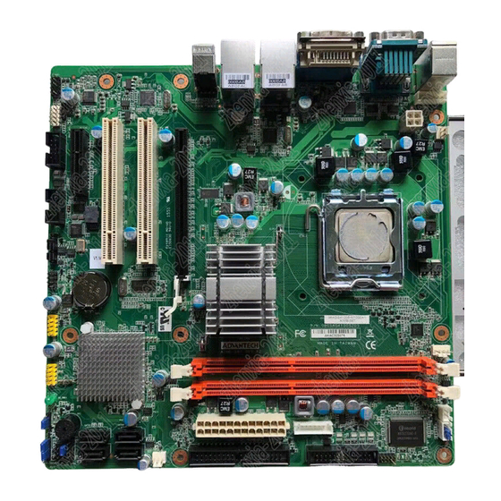
Page 17: Board Layout: Jumper And Connector Locations
SPDIF_OUT1 ATX12V1 LANLED1 SYSFAN2 COM4 BIOS1 COM3 JSETCOM3 SPI_CN1 USB56 ICH7 CPUFAN1 USB78 DIMMA1 DIMMB1 JCMOS1 JCASE1 EATXPWR1 JFSATA1-4 PSON1 FP3/JFP2/JFP3 JWDT1+JOBS1 SYSFAN1 VOLT1 IDE1 LPT1 GPIO1 Figure 1.1 Jumper and Connector Location Figure 1.2 I/O Connectors AIMB-567 User Manual... -
Page 18: Aimb-567 Block Diagram
Edge Connector 4 x PCIe x 1(ICH7R) Audio Codec Intel HD Audio ALC-888 PCI1~2 LPC Bus BIOS Edge Connector Super IO Fintek Winbond 81216AD W83627DHG-P 1 RS232, 1 RS-232/422/485 2 RS-232, WDT, LPT Figure 1.3 AIMB-567 Block Diagram AIMB-567 User Manual... -
Page 19: Safety Precautions
Caution! There is a danger of a new battery exploding if it is incorrectly installed. Do not attempt to recharge, force open, or heat the battery. Replace the battery only with the same or equivalent type recommended by the man- ufacturer. Discard used batteries according to the manufacturer’s instructions. AIMB-567 User Manual... -
Page 20: Jumper Settings
1.8.2 CMOS clear (CMOS1) The AIMB-567 motherboard contains a jumper that can erase CMOS data and reset the system BIOS information. Normally this jumper should be set with pins 1-2 closed. If you want to reset the CMOS data, set J1 to 2-3 closed for just a few sec- onds, and then move the jumper back to 1-2 closed. -
Page 21: Com3 Rs 232/422/485 Mode Selector (Jsetcom3)
DRAMs (DDR3 SDRAM). They are avail- able in capacities of 1024 MB. The sockets can be filled in any combination with DIMMs of any size, giving a total memory size on 4 GB. AIMB-567 does NOT support ECC (error checking and correction). -
Page 22: Cache Memory
The built-in second-level cache in the processor yields much higher performance than conventional external cache memories. 1.12 Processor Installation The AIMB-567 is designed for LGA775, Intel Core 2 Quad, Intel Core 2 Duo, Celeron D and Intel Pentium dual core D processor. AIMB-567 User Manual... -
Page 23: Chapter 2 Connecting Peripherals
Chapter Connecting Peripherals... -
Page 24: Introduction
The parallel port is normally used to connect the motherboard to a printer. The AIMB- 567 includes an onboard parallel port, accessed through a 25-pin flat-cable connec- tor, LPT1. Note! The parallel cable is not enclosed in the box as a standard accessory. The order part number is 1700008809. AIMB-567 User Manual... -
Page 25: Usb Ports (Usb12/Lan2_Usb34/Usb56/Usb78)
USB Ports (USB12/LAN2_USB34/USB56/USB78) The AIMB-567 provides up to eight USB ports (Universal Serial Bus). The USB inter- face complies with USB Specification Rev. 2.0 supporting transmission rates up to 480 Mbps and is fuse protected. The USB interface can be disabled in the system BIOS setup. -
Page 26: Vga Connector (Vga1)
VGA Connector (VGA1) VGA1 The AIMB-567 includes a VGA interface that can drive conventional CRT displays. VGA1 is a standard 15-pin D-SUB connector commonly used for VGA. Pin assign- ments for CRT connector VGA1 are detailed in Appendix B. AIMB-567 User Manual... -
Page 27: Serial Ports (Com1~Com4)
COM3/COM4 COM2 AIMB-567 supports four serial ports - three RS-232, and one RS-232/422/485 - COM3. The user can use JSETCOM3 to select among RS 232/422/485 modes for COM3. These ports can connect to serial devices, such as a mouse or a printer, or to a communications network. -
Page 28: Ps/2 Keyboard And Mouse Connector (Kbms1)
PS/2 Keyboard and Mouse Connector (KBMS1) KBMS1 Two 6-pin mini-DIN connectors (KBMS1) on the motherboard provide connection to a PS/2 keyboard and a PS/2 mouse, respectively. AIMB-567 User Manual... -
Page 29: Cpu Fan Connector (Cpu_Fan1)
CPU Fan Connector (CPU_FAN1) CPU_FAN1 If a fan is used, this connector supports cooling fans of 500 mA (6 W) or less. AIMB-567 User Manual... -
Page 30: System Fan Connector (Sys_Fan1/2)
System FAN Connector (SYS_FAN1/2) SYS_FAN1/2 If a fan is used, this connector supports cooling fans of 500 mA (6 W) or less. AIMB-567 User Manual... -
Page 31: Front Panel Connectors (Jfp1/2/3)
Front Panel Connectors (JFP1/2/3) There are several external switches to monitor and control the AIMB-567. JFP1+JFP2 are for front panel (HDD LED/SNMP SMBus/Speaker pin header/ Power switch). JFP3 is for Power LED and Keyboard lock timer. 2.9.1 ATX Soft Power Switch (JFP1) If your computer case is equipped with an ATX power supply, you should connect the power on/off button on your computer case to JFP1 PIN1, 2. -
Page 32: External Speaker (Jfp2)
2.9.5 SM Bus Connector (JFP2 PIN 6,8) This connector is reserved for Advantech's SNMP-1000 HTTP/SNMP Remote Sys- tem Manager. The SNMP-1000 allows users to monitor the internal voltages, temper- ature and fans from a remote computer through an Ethernet network. -
Page 33: Power Led And Keyboard Lock Connector
1-2 pin closed Connect 1-2 pin cable (On Back plane) with switch Jumper Setting System On System Status Fast flashes Fast flashes Fast flashes System Off Slow flashes JFP3 pin.1 PWR_LED+ pin.2 pin.3 PWR_LED- pin.4 #KB_LOCK pin.5 AIMB-567 User Manual... -
Page 34: Line Out And Mic In Connector (Audio1)
2.10 Line Out and Mic In Connector (AUDIO1) Line Out Mic In AUDIO1 AIMB-567 User Manual... -
Page 35: Serial Ata Interface (Sata 1/2/3/4)
2.11 Serial ATA Interface (SATA 1/2/3/4) SATA1/2/3/4 AIMB-567 features four high performance serial ATA interface (up to 300 MB/s) which eases cabling to hard drives with thin and long cables. AIMB-567 User Manual... -
Page 36: Atx Power Connector (Atx12V1, Eatxpwr1)
The minimum recommended wattage is 230W, or 300W for a fully configured system. The system can become unstable and might experience difficulty powering up if the power supply is inadequate. You must install a PSU with a higher power rating if you intend to install additional devices. AIMB-567 User Manual... -
Page 37: Spi Flash Connector (Spi_Cn1)
2.13 SPI Flash Connector (SPI_CN1) SPI_CN1 SPI flash card pin header can be used to flash the BIOS. AIMB-567 User Manual... -
Page 38: Front Panel Audio Connector (Fpaudio1)
I/O module cable to this connector. FPAUDIO1 Note! For motherboards with the optional HD audio feature, we recommend that you connect a high-definition front panel audio module to this con- nector to avail of the motherboard’s high definition audio capability. AIMB-567 User Manual... -
Page 39: Dvi Connector(Dvi1)
LCD computer displays and digital projectors. It is designed for carrying uncompressed digital video data to a display. with a DVI-D output. DVI1 2.16 Primary EIDE Connector (IDE1) IDE1 AIMB-567 User Manual... -
Page 40: Usb 2.0 Connector (Usb 56, 78)
These USB connectors comply with USB 2.0 specification that sup- ports up to 480 Mbps connection speed. USB56/78 Note! The USB module is purchased separately. AIMB-567 User Manual... -
Page 41: Digital Audio Connector(Spdif_Out1)
This connector is for the S/PDIF audio module to allow digital sound output. Connect one end of the S/PDIF audio cable to this connector and the other end to the S/PDIF module. SPDIF_OUT1 Note! The S/PDIF out module is purchased separately. AIMB-567 User Manual... -
Page 42: Connector To Check Chassis Led Board(Volt1)
2.19 Connector to check chassis LED board(VOLT1) VOLT1 2.20 GPIO Pin Header (GPIO1) GPIO1 AIMB-567 User Manual... -
Page 43: Bios Operation
Chapter BIOS Operation... -
Page 44: Introduction
This chapter describes the basic navigation of the AIMB-567 setup screens. BIOS Setup The AIMB-567 series system has AMI BIOS build-in with a CMOS SETUP utility which allows users to configure required settings or to activate certain system fea- tures. -
Page 45: Main Menu
System Date using the <Arrow> keys. Enter new values through the keyboard. Press the <Tab> key or the <Arrow> keys to move between fields. The date must be entered in MM/DD/YY format. The time must be entered in HH:MM:SS format. AIMB-567 User Manual... -
Page 46: Advanced Bios Features
Allows you to enable or disable C1E support. Configuration options are “Enabled” or “Disabled”. Max CPUID Value Limit Setting this item to [Enabled] allows legacy operating systems to boot even without support for CPUs with extended CPUID functions. Configuration options are “Enabled” or “Disabled”. AIMB-567 User Manual... -
Page 47: Ide/Sata Configuration
Selects the type of IDE drive. Setting to Auto allows automatic selection of the appropriate IDE device type. Select CDROM if you are specially configuring a CD-ROM drive. Select ARMD (ATAPI Removable Media Device) if your device AIMB-567 User Manual... -
Page 48: Super Io Configuration
32Bit Data Transfer Enables or disables 32-bit data transfer. Configuration options are “Disabled” and “Enabled”. 3.2.5 Super IO Configuration This item enables users to set the Super IO device status, including enabling of COMs. Watchdog Timer Watchdog Mode AIMB-567 User Manual... -
Page 49: Hardware Health Configuration
The onboard hardware monitor automatically detects and displays the system temperature. CPU Temperature The onboard hardware monitor automatically detects and displays the CPU temperature. CPUFAN Speed Shows CPU FAN speed [xxxxRPM]. SYSTEMFAN1 Speed Shows SYSTEMFAN1 speed [xxxxRPM]. SYSTEMFAN2 Speed Shows SYSTEMFAN2 speed [xxxxRPM]. AIMB-567 User Manual... -
Page 50: Acpi Setting
[Auto] The system automatically configures the ACPI suspend mode. [S1 (POS) only]Sets the ACPI suspend mode to S1/POS (Power On Suspend). [S3 only] Sets the ACPI suspend mode to S3/STR (Suspend to RAM) AIMB-567 User Manual... -
Page 51: Advanced Acpi Configuration
Allows you to enable or disable RTC to generate a wake event. When this item is set to Enabled, the items RTC Alarm Date, RTC Alarm Hour, RTC Alarm Minute, and RTC Alarm Second appear with set values. Configuration options:[Disabled][Enabled]. AIMB-567 User Manual... -
Page 52: Advanced Pci/Pnp Setting
3.2.11 Advanced PCI/PnP Setting Select the PCI/PnP tab from the AIMB-567 setup screen to enter the Plug and Play BIOS Setup screen. You can display a Plug and Play BIOS Setup option by highlight- ing it using the <Arrow> keys. All Plug and Play BIOS setup options are described in this section. -
Page 53: Boot Setting
If this option is set to Disabled, the BIOS displays normal POST messages. If Enabled, an OEM Logo is shown instead of POST messages. Bootup Num-Lock Select the Power-on state for Numlock. Wait For .F1. If Error Wait for the F1 key to be pressed if an error occurs. AIMB-567 User Manual... -
Page 54: Security Setting
3.2.13 Security Setting Select Security Setup from the AIMB-567 Setup main BIOS setup menu. All Security Setup options, such as password protection and virus protection are described in this section. To access the sub menu for the following items, select the item and press <Enter>:... -
Page 55: North Bridge Chipset Configuration
This item allows you to select which graphics controller is to be used as the pri- mary boot device. Internal Graphics Mode Select Select the amount of system memory used by the Internal graphics device. PEG Port Configuration Enabled/Disabled PEG port configuration. Video Function Configuration Enabled/Disabled video function configuration. AIMB-567 User Manual... -
Page 56: South Bridge Chipset Configuration
Enables or disables the GbE controller. OnBoard LAN1 BootROM Resume on LAN1 Enables or disables GbE LAN wake up from S5 function. SLP_S4# Min. Assertion Width This item allows you to set a delay of a set number of seconds. AIMB-567 User Manual... -
Page 57: Exit Option
Select Discard Changes from the Exit menu and press <Enter>. Load Optimal Defaults The AIMB-567 automatically configures all setup items to optimal settings when you select this option. Optimal Defaults are designed for maximum system per- formance, but may not work best for all computer applications. In particular, do not use the Optimal Defaults if your computer is experiencing system configura- tion problems. - Page 58 AIMB-567 User Manual...
-
Page 59: Chipset Software Installation Utility
Chapter Chipset Software Installation Utility... -
Page 60: Before You Begin
To facilitate the installation of the enhanced display drivers and utility software, read the instructions in this chapter carefully. The drivers for AIMB-567 are located on the software installation CD. The driver in the folder of the driver CD will guide and link you to the utilities and drivers under a Windows system. -
Page 61: Windows Xp/Windows 7 Driver Setup
Windows XP/Windows 7 Driver Setup Insert the driver CD into your system's CD-ROM drive. You can see the driver folder items. Navigate to the "INF" folder and click "setup.exe" to complete the installation of the driver. AIMB-567 User Manual... - Page 62 AIMB-567 User Manual...
-
Page 63: Vga Setup
Chapter VGA Setup... -
Page 64: Introduction
Insert the driver CD into your system’s CD-ROM drive. You can see the driver folders items. Navigate to the "VGA" folder and click "setup.exe" to complete the installation of the drivers for Windows 7, Windows XP. AIMB-567 User Manual... - Page 65 AIMB-567 User Manual...
- Page 66 AIMB-567 User Manual...
-
Page 67: Lan Configuration
Chapter LAN Configuration... -
Page 68: Introduction
Introduction The AIMB-567 has dual Gigabit Ethernet LANs via dedicated PCI Express x1 lanes (Intel 82583V (LAN1) and 82583V (LAN2)) that offer bandwidth of up to 500 MB/ sec, eliminating the bottleneck of network data flow and incorporating Gigabit Ethernet at 1000 Mbps. - Page 69 AIMB-567 User Manual...
- Page 70 AIMB-567 User Manual...
-
Page 71: Appendix A Programming The Watchdog Timer
Appendix Programming the Watchdog Timer... -
Page 72: Programming The Watchdog Timer
Programming the Watchdog Timer The AIMB-567's watchdog timer can be used to monitor system software operation and take corrective action if the software fails to function within the programmed period. This section describes the operation of the watchdog timer and how to pro- gram it. - Page 73 Unlock W83627DHG Select register of watchdog timer Enable the function of the watchdog timer Use the function of the watchdog timer Lock W83627DHG AIMB-567 User Manual...
-
Page 74: Table A.1: Watchdog Timer Registers
Bit 5: Write 1 to generate a timeout signal immedi- ately and automatically return to 0. [default=0] Bit 4: Read status of watchdog timer, 1 means timer is “timeout”. Write this address to I/O port 2E (hex) to lock the AA (hex) ----- watchdog timer 2. AIMB-567 User Manual... -
Page 75: Example Program
Inc dx Mov al,10 Out dx,al ;----------------------------------------------------------- Dec dx ; Lock W83627HG Mov al,0aah Out dx,al Enable watchdog timer and set 5 minutes as timeout interval ;----------------------------------------------------------- Mov dx,2eh ; Unlock W83627HG Mov al,87h Out dx,al Out dx,al AIMB-567 User Manual... - Page 76 Enable watchdog timer to be reset by mouse ;----------------------------------------------------------- Mov dx,2eh ; Unlock W83627HG Mov al,87h Out dx,al Out dx,al ;----------------------------------------------------------- Mov al,07h ; Select registers of watchdog timer Out dx,al Inc dx Mov al,08h Out dx,al ;----------------------------------------------------------- AIMB-567 User Manual...
- Page 77 Dec dx ; Enable the function of watchdog timer Mov al,30h Out dx,al Inc dx Mov al,01h Out dx,al ;----------------------------------------------------------- Dec dx ; Enable watchdog timer to be strobed reset by keyboard Mov al,0f7h Out dx,al Inc dx In al,dx Or al,40h Out dx,al AIMB-567 User Manual...
- Page 78 Dec dx ; Generate a time-out signal Mov al,0f7h Out dx,al ;Write 1 to bit 5 of F7 register Inc dx In al,dx Or al,20h Out dx,al ;----------------------------------------------------------- Dec dx ; Lock W83627HG Mov al,0aah Out dx,al AIMB-567 User Manual...
-
Page 79: Appendix B I/O Pin Assignments
Appendix I/O Pin Assignments... -
Page 80: Parallel Port (Lpt1)
Parallel Port (LPT1) Table B.1: Parallel Port (LPT1) Signal Signal STROBE* AUTOFD* INIT* SLCTINI* ACK* BUSY SLCT * Low activity USB Header (USB56) Table B.2: USB Header (USB56) Signal Signal USB0_VCC5 USB1_VCC5 USB0_D- USB1_D- USB0_D+ USB1_D+ AIMB-567 User Manual... -
Page 81: Usb Header (Usb78)
USB Header (USB78) Table B.3: USB Header (USB78) Signal Signal USB0_VCC5 USB1_VCC5 USB0_D- USB1_D- USB0_D+ USB1_D+ VGA Connector (VGA1) Table B.4: VGA Connector (VGA1) Signal Signal CRT_VCCIN VGA_G VGA_B V_SDAT H-SYNC V-SYNC V_SCLK AIMB-567 User Manual... -
Page 82: Rs-232 Interface (Com1-Com4)
RS-232 Interface (COM1-COM4) Table B.5: RS-232 Interface (COM1~COM2) Signal RS-232/422/485 Setting Interface (JETCOM3) Table B.6: RS-232/422/485 Setting Interface (JETCOM3) Signal Signal R_SINA RXD485_1 R_SINA RXD422_1 R_SINA RXD232_1 DCDA SOUTA COM1_DCD# COM1_SOUT COM1_TXD485N COM1_RXD485P SINA DTRA COM1_SIN COM1_DTR# COM1_TXD485P COM1_RXD485N AIMB-567 User Manual... -
Page 83: Spi_Cn1: Spi Fresh Card Pin Connector
Table B.7: SPI_CN1:SPI fresh card pin connector Signal Signal +F1_3V F1_SPI_CS#_Q F1_SPI_CLK_Q F1_SPI_MISO_Q F1_SPI_MOSI_Q PS/2 Keyboard and Mouse Connector (KBMS1) Table B.8: PS/2 Keyboard and Mouse Connector (KBMS1) Signal KB DATA KB VCC KB CLK M_DATA M_VCC M_CLK AIMB-567 User Manual... -
Page 84: Cpu Fan Power Connector (Cpu_Fan1)
CPU Fan Power Connector (CPU_FAN1) Table B.9: CPU Fan Power Connector (CPU_FAN1) Signal +12 V PWM DETECT B.10 System Fan Power Connector (SYS_FAN1/ SYS_FAN2) Table B.10: System Fan Power Connector (SYSFAN1/SYSFAN2) Signal DETECT AIMB-567 User Manual... -
Page 85: Front Panel Connectors (Jfp1/2)
Power switch/HDD LED/SMBus/Speaker (JFP1/JFP2) The single board computer has its own buzzer. You can also connect it to the external speaker on your computer chassis. Table B.12: Power Switch/HDD LED/SMBus/Speaker (JFP1/JFP2) Signal Signal HDDLED+ HDDLED- SMB_DAT SYS_RST SMB_CLK SYS_RST AIMB-567 User Manual... -
Page 86: Atx1 12 V Auxiliary Power Connector (Atx12V1)
ATX Power Connector (EATXPWR1) Table B.14: ATX Power Connector (ATX2) Signal Signal +3.3 V +3.3 V +5 V +5 V 5 VSB + 12 V + 12 V 3.3 V 3.3 V -12 V PSON -5 V AIMB-567 User Manual... -
Page 87: Usb/Lan Ports (Lan1/2_Usb12/Usb34)
Table B.16: Ethernet 10/100Base-T RJ-45 Port Signal Signal XMT+ XMT- RCV- RCV+ B.15 Line Out, Mic In Connector (AUDIO1) Line Out Mic In B.16 Serial ATA0 (SATA1) Table B.17: Serial ATA0 (SATA1) Signal Signal SATA_0TX+ SATA_0TX- SATA_0RX- SATA_0RX+ AIMB-567 User Manual... -
Page 88: Serial Ata1 (Sata2)
FPAUDIO1(Front Panel Audio Connector) Table B.20: Front Panel Audio Connector (FPAUDIO1) Signal MIC2_L AGND MIC2_R PRESENSE LIN2_R FIO_JD LIN2_L B.20 GPIO1(GPIO pin header) Table B.21: GPIO pin header(GPIO1) Signal Signal DIO_GP20 DIO_GP22 DIO_GP24 DIO_GP26 DIO_GP21 DIO_GP23 DIO_GP25 DIO_GP27 AIMB-567 User Manual... -
Page 89: System I/O Ports
Prototype card 360-36F Reserved 378-37F Parallel printer port 1 (LPT2) 380-38F SDLC, bisynchronous 2 3A0-3AF Bisynchronous 1 3B0-3BF Monochrome display and printer adapter (LPT1) 3C0-3CF Reserved 3D0-3DF Color/graphics monitor adapter 3F0-3F7 Diskette controller 3F8-3FF Serial port 1 AIMB-567 User Manual... -
Page 90: Jcase1(Open Case Connector)
IRQ12 PS/2 mouse IRQ13 INT from co-processor IRQ14 Primary IDE Channel IRQ15 Secondary IDE Channel IRQ3 Serial communication port 2 IRQ4 Serial communication port 1 IRQ5 Available IRQ6 Diskette controller (FDC) IRQ7 Parallel port 1 (print port) AIMB-567 User Manual... -
Page 91: St Mb Memory Map
1st MB Memory Map Table B.27: 1st MB Memory Map Addr. range (Hex) Device E0000h - FFFFFh BIOS CC000h - DFFFFh Unused C0000h - CBFFFh VGA BIOS A0000h - BFFFFh Video Memory 00000h - 9FFFFh Base memory AIMB-567 User Manual... - Page 92 No part of this publication may be reproduced in any form or by any means, electronic, photocopying, recording or otherwise, without prior written permis- sion of the publisher. All brand and product names are trademarks or registered trademarks of their respective companies. © Advantech Co., Ltd. 2010...
Need help?
Do you have a question about the AIMB-567 and is the answer not in the manual?
Questions and answers