
Related Manuals for Advantech AIMB-501


Summary of Contents for Advantech AIMB-501
- Page 1 User Manual AIMB-501 Intel® Core™ i7/i5/i3/Celeron and Pentium® LGA1155 Micro ATX with VGA/DVI/LVDS, 10 COM, Dual Lan, 4 SATA II, 10 USB 2.0, PCIe x 16, PCIe x 1, 2...
- Page 2 The documentation and the software included with this product are copyrighted 2012 by Advantech Co., Ltd. All rights are reserved. Advantech Co., Ltd. reserves the right to make improvements in the products described in this manual at any time without notice.
- Page 3 Whether your new Advantech equipment is destined for the labo- ratory or the factory floor, you can be assured that your product will provide the reliability and ease of operation for which the name Advantech has come to be known.
-
Page 4: Declaration Of Conformity
Intel® Pentium® Processor G850 SR05Q 5 GT/s 32nm NA NA LGA1155 PASS 2.90 GHz Intel® Core™ i5- 3550S Processor QC14 32nm NA NA LGA1155 PASS 3.0GHz Intel® Core™ i7- 3770 Processor NA NA LGA1155 PASS 3.4 GHz AIMB-501 User Manual... -
Page 5: Ordering Information
CRT DVI LVDS USB2.0 COM TPM LAN Acronis McAfee Storage Number slot slot Access Label 2009 AIMB- 501G2- (3W x 2) KSA1E AIMB-501L- KSA1E AIMB- 501G2F- (3W x 2) KSA1E AIMB- 501LF- KSA1E *() not populated on MP version. AIMB-501 User Manual... - Page 6 It should be free of marks and scratches and in perfect working order upon receipt. As you unpack the AIMB-501, check it for signs of ship- ping damage. (For example, damaged box, scratches, dents, etc.) If it is damaged or it fails to meet the specifications, notify our service department or your local sales representative immediately.
-
Page 7: Table Of Contents
Board layout: Jumper and Connector Locations ........5 Figure 1.1 Jumper and Connector Location ........ 5 Figure 1.2 I/O Connectors ............5 AIMB-501 Board Diagram ................. 6 Figure 1.3 AIMB-501 Block Diagram ........... 6 Safety Precautions ..................7 Jumper Settings ..................7 1.8.1 How to Set Jumpers.............. - Page 8 Security Setting..................62 Save & Exit Configuration ............... 63 Chapter Chipset Software Installation Utility Before You Begin..................66 Introduction ..................... 66 Windows XP/Windows 7 Driver Setup ............ 67 Chapter VGA Setup ......... 69 Introduction ..................... 70 AIMB-501 User Manual viii...
- Page 9 VOLT Connector (VOLT1) ..............92 Table B.17:VOLT Connector (VOLT1)........93 B.18 Front Audio Header (FPAUD1) ............... 93 Table B.18:Front Audio Header (FPAUD1)......... 93 B.19 ATX 24-pin Power Connector (EATXPWR1 ) ......... 94 Table B.19:ATX 24-pin Power Connector (EATXPWR1 )... 94 AIMB-501 User Manual...
- Page 10 Table B.25:Debug Port (LPC1)..........98 B.26 DMA Channel Assignments ..............99 Table B.26:DMA Channel Assignments ........99 B.27 Interrupt Assignments ................99 Table B.27:Interrupt Assignments ..........99 B.28 1st MB Memory Map................99 Table B.28:1st MB Memory Map ..........99 AIMB-501 User Manual...
-
Page 11: Chapter 1 General Information
Chapter General Information... -
Page 12: Introduction
Introduction AIMB-501 is designed with the Intel H61 for industrial applications that require both performance computing and enhanced power management capabilities. The mother- board supports Intel Core i7-3770 3.4 GHz/Core i5-3550S 3.0 GHz/Core i7-2600 3.4 GHz/Core i5-2400 3.1 GHz/Core i3-2120 3.3 GHz/ Pentium G850 2.9 GHz/Celeron G540 2.5 GHz processor up to 8 MB L3 cache and DDR3 1333/1600 up to 16 GB. -
Page 13: Input/Output
USB port: Supports up to 10 USB 2.0 ports with transmission rates up to 480 Mbps. GPIO: AIMB-501 supports 8-bit GPIO from super I/O for general purpose con- trol application. 1.3.4 Graphics Controller: Intel® HD Graphics ... -
Page 14: Jumpers And Connectors
Jumpers and Connectors Connectors on the AIMB-501 motherboard link it to devices such as hard disk drives and a keyboard. In addition, the board has a number of jumpers used to configure your system for your application. The tables below list the function of each of the board jumpers and connectors. Later sections in this chapter give instructions on setting jumpers. -
Page 15: Board Layout: Jumper And Connector Locations
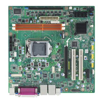
DVI1 CPU_FAN1 PSON1 USB23 SMBUS1 COM2 USB01 COM1 DUALPWR2 DIMM_A1 DIMM_B1 VOLT1 SPI_CN1 SATA4 JFP1+JFP2 JFP3 SATA3 SATA1 COM78910 COM3456 SATA2 JWDT1+JOBS1 JSETCOM3 JSETCOM7 GPIO1 SYSFAN2 EATXPWR1 Figure 1.1 Jumper and Connector Location Figure 1.2 I/O Connectors AIMB-501 User Manual... -
Page 16: Aimb-501 Board Diagram
USB 2.0 LPC BUS Audio Codec BIOS Realtek ALC892 Fintek Fintek Super I/O (Optional) 81216AD 81216AD Nuvuton 6776F 4 RS-232 4 RS-232 2 x RS-232, (1 w/RS-422/485) (1 w/RS-422/485) PS/2, Parallel, GPIO,WDT Figure 1.3 AIMB-501 Block Diagram AIMB-501 User Manual... -
Page 17: Safety Precautions
1, 2, and 3. In this case you connect either pins 1 and 2, or 2 and 3. A pair of needle-nose pliers may be useful when set- ting jumpers. AIMB-501 User Manual... -
Page 18: Cmos Clear (Cmos1)
1.8.2 CMOS Clear (CMOS1) The AIMB-501 motherboard contains a jumper that can erase CMOS data and reset the system BIOS information. Normally this jumper should be set with pins 1-2 closed. If you want to reset the CMOS data, set CMOS1 to 2-3 closed for just a few seconds, and then move the jumper back to 1-2 closed. -
Page 19: Jlvds_Vbr1: Backlight Control Selector For Lvds1
ATX Mode Default 1.8.6 JWDT1+JOBS1: Watchdog Timer Output and OBS Alarm Option Table 1.7: JWDT1+JOBS1: Watchdog Timer Output and OBS Alarm Option Closed Pins Result *2-3 Reset *4-5 Enable OBS function (4-5 open: disable OBS function) *: Default AIMB-501 User Manual... -
Page 20: Com3/Com7 Rs232/422/485 Mode Selector (Jsetcom3 & Jsetcom7)
(1-2) + (9-11) + (10-12) + (15-17) + (16-18) closed *: Default 1.8.8 CN1/CN2: Power setting for COM1 & COM2 Table 1.9: CN1/CN2: Power setting for COM1 & COM2 Setting Function No power with 5V with 12V AIMB-501 User Manual... -
Page 21: Jcase1: Case Open Sensor
1.11 Cache Memory The AIMB-501 supports a CPU with one of the following built-in full speed L3 caches: 8 MB for Intel Core i7-3770 6 MB for Intel Core i5-3550S... - Page 22 AIMB-501 User Manual...
-
Page 23: Chapter 2 Connecting Peripherals
Chapter Connecting Peripherals... -
Page 24: Introduction
USB Ports (LAN1_USB12/LAN2_USB34/USB01/ USB23/USB45) The AIMB-501 provides up to 10 USB ports. The USB interface complies with USB Specification Rev 2.0 supporting transmission rates up to 480 Mbps. The USB inter- face can be disabled in the system BIOS setup. -
Page 25: Usb Power Switch
USB Power Switch AIMB-501 allows users to set USB power between +5VSB and +5V. When the jumper is set as 2-3, do not tick "Allow this device to bring the computer out of standby" under device manager (as below figure 2.1) if users do not request to have the board wake up from S3 via USB device keyboard or mouse. -
Page 26: Vga1/ Dvi-D Connector (Vga1 + Vga2 + Dvi1)
VGA1 DVI1 VGA2 AIMB-501 includes VGA and DVI interfaces that can drive conventional VGA and DVI displays. VGA is a standard 15-pin D-SUB connector commonly used for VGA. Pin assignments for VGA and DVI connectors are detailed in Appendix B. -
Page 27: Serial Ports (Com1~Com10)
COM1 COM3/4/5/6 COM7/8/9/10 AIMB-501 supports ten serial ports. COM1. COM2. COM4-6. COM8-10 supports RS- 232. COM3 & COM7 supports RS-232/422/485 (supports RS-485 auto flow control). JSETCOM3 & JSETCOM7 is used to select the RS-232/422/485 mode for COM3 & COM7. COM1 & COM2 is with selectable 5V/12V power.. -
Page 28: Ps/2 Keyboard And Mouse Connector (Kbms1)/External Ps/2 Keyboard And Mouse Connector (Kbms2)
KBMS2 Two 6-pin mini-DIN connectors (KBMS1) on the motherboard provide connection to a PS/2 keyboard and a PS/2 mouse, respectively. KBMS2 is for supporting the 2nd PS/ 2 keyboard and PS/2 mouse by a cable P/N 1700018699. AIMB-501 User Manual... -
Page 29: Cpu Fan Connector (Cpu_Fan1)
If a fan is used, this connector supports cooling fans of 500 mA (6 W) or less. System FAN Connector (SYSFAN1/2) SYSFAN1 SYSFAN2 If a fan is used, this connector supports cooling fans of 500 mA (6 W) or less. AIMB-501 User Manual... -
Page 30: Front Panel Connectors (Jfp1/Jfp2/Jfp3)
Front Panel Connectors (JFP1/JFP2/JFP3) There are several headers for monitoring and controlling the AIMB-501. JFP1+ JFP2 JFP3 JFP3 Front panel connector Pin Name SIO_SUSLED #KEYLOCK AIMB-501 User Manual... -
Page 31: Line Out, Mic In Connector (Audio1)
2.10 Line Out, Mic In Connector (AUDIO1) AUDIO1 AIMB-501 User Manual... -
Page 32: Smbus Header (Smbus1)
It can be configured to I2C by customer's request. SMBUS1 2.12 Serial ATA Interface (SATA1 ~ SATA4) SATA4 SATA3 SATA1 SATA2 AIMB-501 features a high performance Serial ATA interface (up to 300 MB/s) which eases hard drive cabling with thin, space-saving cables. AIMB-501 User Manual... -
Page 33: Adjust Audio Volumn Connector (Vol_Adj1)
VOL_ADJ1 VOL_ADJ1 Adjust audio volume Pin Name AMP_L_OUT_C AMP_L_OUT AMP_R_OUT AMP_R_OUT_C VOL_ADJ1 connects to the alarm board on the chassis. These alarm boards give warnings if a power supply or fan fails, or if the chassis overheats. AIMB-501 User Manual... -
Page 34: Pci Express X16 Slot
2.14 PCI express x16 slot PCIEx16_1 AIMB-501 provides a PCIe x16 slot for users to install add-on cards when their appli- cations require higher graphic performance than the CPU embedded graphics con- troller can provide. AIMB-501 User Manual... -
Page 35: Front Headphone Connector (Fpaud1)
SENSE_B LIN2_L LIN2_JD Note! For motherboards with the optional HD Audio feature, we recommend that you connect a high-definition front panel audio module to this con- nector to take advantage of the motherboard’s high definition audio capability. AIMB-501 User Manual... -
Page 36: Atx Power Connector (Eatxpwr1, Atx12V1)
Please connect the ATX12V1 connector with the PSU ATX 12V 4- pin connector. For a fully configured system, we recommend that you use a power supply unit (PSU) that complies with ATX 12 V Specification 2.0 (or later version) and provides a minimum power of 180 W. AIMB-501 User Manual... -
Page 37: Spi Flash Connector(Spi_Cn1)
2.17 SPI Flash connector(SPI_CN1) The SPI flash card pin header may be used to flash the BIOS if the AIMB-501 cannot power on. SPI_CN1 SPI_CN1 SPI connector Pin Name SPI_POWER SPI_CS# SPI_CLK SPI_MISO SPI_MOSI SPI_HOLD# AIMB-501 User Manual... -
Page 38: Lcd Inverter Connector (Inv1)
2.18 LCD Inverter Connector (INV1) INV1 INVI Inverter Power Output Pin Name +12V ENABKL AIMB-501 User Manual... -
Page 39: Lvds Connector (Lvds1)
2.19 LVDS Connector (LVDS1) LVDS1 2.20 General Purpose I/O Connector (GPIO1) GPIO1 GPIO1 GPIO connector Pin Name SIO_SPIO0 SIO_SPIO1 AIMB-501 User Manual... -
Page 40: Lpc Connector For Debug (Lpc1)
SIO_SPIO2 SIO_SPIO3 SIO_SPIO4 SIO_SPIO5 SIO_SPIO6 SIO_SPIO7 VCC_GPIO 2.21 LPC Connector for Debug (LPC1) LPC1 AIMB-501 User Manual... -
Page 41: Bios Operation
Chapter BIOS Operation... -
Page 42: Introduction
BIOS Setup The AIMB-501 Series system has AMI BIOS built in, with a CMOS SETUP utility that allows users to configure required settings or to activate certain system features. The CMOS SETUP saves the configuration in the CMOS RAM of the motherboard. -
Page 43: Main Bios Setup
System Date using the <Arrow> keys. Enter new values through the keyboard. Press the <Tab> key or the <Arrow> keys to move between fields. The date must be entered in MM/DD/YY format. The time must be entered in HH:MM:SS format. AIMB-501 User Manual... -
Page 44: Advanced Bios Features
3.3.1 Advanced BIOS Features Select the Advanced tab from the AIMB-501 setup screen to enter the Advanced BIOS Setup screen. You can select any of the items in the left frame of the screen, such as CPU Configuration, to go to the sub menu for that item. You can display an Advanced BIOS Setup option by highlighting it using the <Arrow>... -
Page 45: Pci Configuration
PCI bus. The Optimal and Fail-Safe default setting is 32. VGA Palette Snoop Set this value to allow the system to modify the VGA Palette Snoop settings. The Optimal and Fail-Safe default setting is "Disabled". AIMB-501 User Manual... -
Page 46: Pci Express Settings
3.3.3 PCI Express Settings Link Training Retry To adjust the retry times when PCIE Link failure Link Training Timeout To set up timeout for link training AIMB-501 User Manual... -
Page 47: Acpi Settings
This item allows users to enable or disable Hibernation. ACPI Sleep State This item allows users to set the ACPI sleep state Lock Legacy Resources This item allows users to lock legacy devices’ resources. S3 Video Repost Enable or disable video repost. AIMB-501 User Manual... -
Page 48: Trusted Computing
3.3.5 Trusted Computing Security Device Support Enable or disable BIOS support for security device. 3.3.6 S5 RTC wake Settings Wake system with fixed time Enable or disable system wake on alarm event. AIMB-501 User Manual... -
Page 49: Sata Configuration
3.3.7 SATA Configuration SATA Controllers To enable or disable SATA controller. SATA Mode Selection This can be configured as IDE or AHCI mode. 3.3.8 Intel Trusted Execution Technology Configuration AIMB-501 User Manual... -
Page 50: Usb Configuration
EHCI Hand-off This is just a workaround item under OS without EHCI hand-off support. USB hardware delays and time-outs To set up parameter for detect USB device. Mass Storage Devices Shows USB mass storage device information. AIMB-501 User Manual... -
Page 51: Super Io Configuration
3.3.10 Super IO Configuration Serial Port 1 Configuration Serial Port To “enable” or “disable” Serial Port 1. Change Settings To select the IO address/IRQ setting for serial port 1. AIMB-501 User Manual... - Page 52 Serial Port 2 Configuration Serial Port To “enable” or “disable” Serial Port 2. Change Settings To select the IO address/IRQ setting for serial port 2. AIMB-501 User Manual...
-
Page 53: Parallel Port Configuration
3.3.11 Parallel Port Configuration Parallel Port To enable or disable Parallel Port. 3.3.12 Super IO Configuration Serial Port 3 Configuration Serial Port AIMB-501 User Manual... - Page 54 When the COM is to set as RS-485, it supports auto flow control function. Serial Port 4 Configuration Serial Port To “enable” or “disable” Serial Port 4. Change Settings To select the IO address/IRQ setting for serial port 4. AIMB-501 User Manual...
- Page 55 Serial Port 5 Configuration Serial Port To ‚”enable” or “disable” Serial Port 5. Change Settings To select the IO address/IRQ setting for serial port 5. AIMB-501 User Manual...
- Page 56 To “enable” or “disable” Serial Port 7. Change Settings To select the IO address/IRQ setting for serial port 7. Auto flow control When the COM is to set as RS-485, it supports auto flow control function. AIMB-501 User Manual...
- Page 57 Serial Port 8 Configuration Serial Port To “enable” or “disable” Serial Port 8. Change Settings To select the IO address/IRQ setting for serial port 8. Serial Port 9 Configuration Serial Port AIMB-501 User Manual...
- Page 58 To select the IO address/IRQ setting for serial port 9. Serial Port 10 Configuration Serial Port To “enable” or “disable” Serial Port 10. Change Settings To select the IO address/IRQ setting for serial port 10. AIMB-501 User Manual...
-
Page 59: Smart Fan Configuration
3.3.13 Smart Fan Configuration CPU Smart Fan To enable or disable CPU smart fan. System Smart Fan To enable or disable System Smart Fan. AIMB-501 User Manual... - Page 60 Use this to set the CPU warning temperature threshold. When the system CPU reaches the warning temperature, the buzzer will beep. ACPI Shutdown Temperature This screen allows users to set the CPU temperature at which the system will automatically shut down to prevent the CPU from overheating damage. AIMB-501 User Manual...
-
Page 61: Cpu Ppm Configuration
Users can display a Chipset Setup option by highlighting it using the <Arrow> keys. All Chipset Setup options are described in this section. The Chipset Setup screens are shown below. The sub menus are described on the following pages. AIMB-501 User Manual... -
Page 62: Pch-Io Configuration
3.4.1 PCH-IO Configuration PCI Express Configuration Detail of PCI Express items. USB Configuration Details of USB items. PCH Azalia Configuration Details of PCH azalia items. AIMB-501 User Manual... - Page 63 Restore AC Power Loss This item allows users to select off, on and last state. 3.4.1.1 PCI Express Configuration PCI Express Clock Gating Enable or disable PCI express clock gating. Subtractive Decode Enable or disable Subtractive decode. AIMB-501 User Manual...
- Page 64 3.4.1.2 PCI Express Root Port 1/2/3 AIMB-501 User Manual...
- Page 65 Enable or disable Root PCI Express System Error on Correctable Error. PME SCI Enable or disable PCI Express PME SCI. Hot Plug Enable or disable PCI Express Hot Plug. PCIe Speed Select PCI Express port speed. Extra Bus Reserved AIMB-501 User Manual...
-
Page 66: Usb Configuration
Reserved I/O (4K/8K/12K/16K/20K) Range for this Root Bridge 3.4.2 USB Configuration EHCI 1/2 Enables or disables the EHCI controller. USB Ports pre-port Disable Control This item allows users to enable or disable each USB port individually. AIMB-501 User Manual... -
Page 67: Pch Azalia Configuration
3.4.3 PCH Azalia Configuration Azalia This item allows user to enable or disable azalea device. 3.4.4 System agent Configuration AIMB-501 User Manual... - Page 68 This item allows users to select DVMT pre-allocated memory size. DVMT Total Gfx Mem This item allows users to select DVMT total memory size. LCD Control This item allows users to setup Display Control configuration. AIMB-501 User Manual...
- Page 69 This items allow users to select the video device which will be activated during post. The available options are VBIOS Default, VGA1, LVDS/VGA2, DVI. SDVO-LFP Panel Type: 1024 x 768 18-bit 1024 x 768 24-bit 1280 x 1024 48-bit 1366 x 768 24-bit AIMB-501 User Manual...
-
Page 70: Nb Pcie Configuration
PEG0 ASPM=> Enable/Disable PEG0 ASPM function. (ASPM: Active State Power Management) Enable PEG This item allows users to enable or disable PEG always. Detect Non-Compliance Device This item allows users to enable or disable Detect Non-Compliance Device function. AIMB-501 User Manual... -
Page 71: Memory Information
3.4.6 Memory Information Memory Frequency Limiter Select memory frequency limiter for auto, 1067, 1333, 1600. Boot Configuration AIMB-501 User Manual... -
Page 72: Security Setting
Set the system boot order. Security Setting Select Security Setup from the AIMB-501 Setup main BIOS setup menu. All Security Setup options, such as password protection and virus protection are described in this section. To access the sub menu for the following items, select the item and press<Enter>: Change Administrator / User Password. -
Page 73: Save & Exit Configuration
Defaults if the user's computer is experiencing system configuration problems. Select Restore Defaults from the Exit menu and press <Enter>. Save as User Default Save the all current settings as a user default. Restore User Default AIMB-501 User Manual... - Page 74 Restore all settings to user default values. Boot Override Shows the boot device types on the system. AIMB-501 User Manual...
-
Page 75: Chipset Software Installation Utility
Chapter Chipset Software Installation Utility... -
Page 76: Before You Begin
To facilitate the installation of the enhanced display drivers and utility software, read the instructions in this chapter carefully. The drivers for AIMB-501 are located on the software installation CD. The driver in the folder of the driver CD will guide and link you to the utilities and drivers under a Windows system. -
Page 77: Windows Xp/Windows 7 Driver Setup
Windows XP/Windows 7 Driver Setup Insert the driver CD into your system's CD-ROM drive. You can see the driver folder items. Navigate to the "Intel chip" folder and click "Setup.exe" to complete the installation of the driver. AIMB-501 User Manual... - Page 78 AIMB-501 User Manual...
-
Page 79: Vga Setup
Chapter VGA Setup... -
Page 80: Introduction
See Chapter 5 for information on installing the CSI util- ity. Insert the driver CD into your system's CD-ROM drive. Navigate to the "Intel Graph- ics" folder and click "setup.exe" to complete the installation of the drivers for Win- dows 7 and Windows XP. AIMB-501 User Manual... -
Page 81: Chapter 6 Lan Configuration
Chapter LAN Configuration... -
Page 82: Introduction
Introduction The AIMB-501 has dual Gigabit Ethernet LANs via dedicated PCI Express x1 lanes (Realtek RTL8111E-VL (LAN1) and Realtek RTL8111E-VL (LAN2)) that offer band- width of up to 500 MB/sec, eliminating the bottleneck of network data flow and incor- porating Gigabit Ethernet at 1000 Mbps. - Page 83 Appendix Programming the Watchdog Timer...
-
Page 84: Appendix A Programming The Watchdog Timer
Programming the Watchdog Timer AIMB-501's watchdog timer can be used to monitor system software operation and take corrective action if the software fails to function within the programmed period. This section describes the operation of the watchdog timer and how to program it. - Page 85 Unlock NCT6776F Select register of watchdog timer Enable the function of the watchdog timer Use the function of the watchdog timer Lock NCT6776F AIMB-501 User Manual...
-
Page 86: Table A.1: Watchdog Timer Registers
Bit 5: Write 1 to generate a timeout signal immedi- ately and automatically return to 0. [default=0] Bit 4: Read status of watchdog timer, 1 means timer is “timeout”. Write this address to I/O port 2E (hex) to lock the AA (hex) ----- watchdog timer 2. AIMB-501 User Manual... -
Page 87: Example Program
Inc dx Mov al,10 Out dx,al ;----------------------------------------------------------- Dec dx ; Lock NCT6776F Mov al,0aah Out dx,al Enable watchdog timer and set 5 minutes as timeout interval ;----------------------------------------------------------- Mov dx,2eh ; Unlock NCT6776F Mov al,87h Out dx,al Out dx,al AIMB-501 User Manual... - Page 88 Enable watchdog timer to be reset by mouse ;----------------------------------------------------------- Mov dx,2eh ; Unlock NCT6776F Mov al,87h Out dx,al Out dx,al ;----------------------------------------------------------- Mov al,07h ; Select registers of watchdog timer Out dx,al Inc dx Mov al,08h Out dx,al ;----------------------------------------------------------- AIMB-501 User Manual...
- Page 89 Dec dx ; Enable the function of watchdog timer Mov al,30h Out dx,al Inc dx Mov al,01h Out dx,al ;----------------------------------------------------------- Dec dx ; Enable watchdog timer to be strobed reset by keyboard Mov al,0f7h Out dx,al Inc dx In al,dx Or al,40h Out dx,al AIMB-501 User Manual...
- Page 90 Dec dx ; Generate a time-out signal Mov al,0f7h Out dx,al ;Write 1 to bit 5 of F7 register Inc dx In al,dx Or al,20h Out dx,al ;----------------------------------------------------------- Dec dx ; Lock NCT6776F Mov al,0aah Out dx,al AIMB-501 User Manual...
-
Page 91: Appendix B I/O Pin Assignments
Appendix I/O Pin Assignments... -
Page 92: Lan&Usb Connector (Lan1_Usb12, Lan2_Usb34)
LAN&USB Connector (LAN1_USB12, LAN2_USB34) Table B.1: LAN&USB Connector (LAN1_USB12, LAN2_USB34) LAN1_USB12, LAN2_USB34 LAN&USB Connector Part Number 12GA1652003674 Pin Name LAN_MDI0_P LAN_MDI0_N LAN_MDI1_P LAN_MDI1_N LAN_MDI2_P LAN_MDI2_N LAN_MDI3_P LAN_MDI3_N LAN_ACT# LAN_ACTP LINKLED#_N LINKLED#_Q +USBV89 LP9- LP9+ +USBV89 LP8- LP8+ AIMB-501 User Manual... -
Page 93: Usb Connector (Usb01/23/45)
Table B.3: USB/PS2 KBMS Power Setting (DUALPWR3/DUALPWR2) DUALPWR3/DUALPWR2 USB/PS2 KBMS Power Setting Setting Function Pin Name USB/PS2 KBMS power from MOS USB/PS2 KBMS power from +5V DUALPWR2- Jumper for on board USB DUALPWR3- Jumper for rear side USB & PS/2 KBMS AIMB-501 User Manual... -
Page 94: Vga Connector (Vga1/Vga2)
VGA connector (VGA1/VGA2) Table B.4: USB Connector (USB01/23/45) VGA1/VGA2 VGA Connector Part Number 12G101152158 Pin Name GREEN BLUE DATA HSYNC VSYNC DCLK AIMB-501 User Manual... -
Page 95: Dvi Connector (Dvi1)
DVI Connector (DVI1) Table B.5: DVI Connector (DVI1) DVI1 DVI Connector Part Number 12GS1600030H03 Pin Name DVI_TMDS_DATA0_N +5V_DVI DVI_TMDS_DATA0_P DVI_TMDS_CLK_P DVI_TMDS_CLK_N DVI_TMDS_DATA1_N DVI_TMDS_DATA1_P TMDS1_DDC_SC TMDS1_DDC_SD DVI_TMDS_DATA2_N TMDS1_HPD DVI_TMDS_DATA2_P +5V_DVI AIMB-501 User Manual... -
Page 96: Com Port Connector (Com1/Com2)
COM Port Connector (COM1/COM2) Table B.6: COM Port Connector (COM1/COM2) COM1/COM2 COM Port Connector Part Number 12G07120010T Pin Name DDCD1# DDSR1# RRXD1 RRTS1# TTXD1 CCTS1# DDTR1# COM1_RRI1 COM Port Connector (COM3456/COM78910) AIMB-501 User Manual... -
Page 97: Table B.7: Com Port Connector (Com3456/Com78910)
Part Number 12G07120010T Pin Name COM3_1 DDSR3# COM3_2 RRTS3# COM3_3 CCTS3# COM3_4 RRI3# DDCD4# DDSR4# RRXD4 RRTS4# TTXD4 CCTS4# DDTR4# RRI4# DDCD5# DDSR5# RRXD5 RRTS5# TTXD5 CCTS5# DDTR5# RRI5# DDCD6# DDSR6# RRXD6 RRTS6# TTXD6 CCTS6# DDTR6# RRI6# AIMB-501 User Manual... -
Page 98: Kb/Ms Connector (Kbms1)
Table B.8: KB/MS Connector (KBMS1) KBMS1 KB/MS Connector Part Number 12G14101306P Pin Name CKBDATA +5V_KBMS CKBCLK CMSDATA +5V_KBMS CMSCLK KB/MS Header (KBMS2) Table B.9: KB/MS Header (KBMS2) KBMS2 KB/MS Header Part Number 12GA1655006020 Pin Name CKBCLK CKBDATA CMSDATA +5V_KBMS CMSCLK AIMB-501 User Manual... -
Page 99: Cpu Fan Connector (Cpu Fan1)
SYS FAN1/SYS FAN2 System Fan Connector Part Number 12G08002003C Pin Name SYS1_SFAN_PWR SYS1_SFAN_D B.12 Front Panel Connector (JFP1+JFP2) The single board computer has its own buzzer. You can also connect it to the external speaker on your computer chassis. AIMB-501 User Manual... -
Page 100: Front Panel Connector (Jfp3)
B.13 Front Panel Connector (JFP3) Table B.13: Front Panel Connector (JFP3) JFP3 Front Panel Connector Part Number 12G06000005C Pin Name SIO_SUSLED #KEYLOCK Note: Pin1,3 provide LED function ; Pin4,5 provide the ability to lock PS/2 (KBMS) . AIMB-501 User Manual... -
Page 101: Audio Jack (Audio1)
B.14 Audio jack (AUDIO1) Table B.14: Audio Jack (AUDIO1) AUDIO1 Audio Jack Part Number 12GS2400005F04 Pin Name LIN1_L LIN1_JD LIN1_R FRONT_L FRONT_JD FRONT_R MIC1_L MIC1_JD MIC1_R B.15 SM BUS Connector (SMBUS1) AIMB-501 User Manual... -
Page 102: Sata Connector (Sata1/2/3/4)
Table B.15: SM BUS Connector (SMBUS1) SMBUS1 SM BUS Connector Part Number 12GA1655001154 Pin Name SMB_CLK_MAIN SMB_DATA_MAIN B.16 SATA Connector (SATA1/2/3/4) Table B.16: SATA Connector (SATA1/2/3/4) SATA1/2/3/4 SATA Connector Part Number 12GP24-006R000 Pin Name SATA_TXP0_C SATA_TXN0_C SATA_RXN0_C SATA_RXP0_C B.17 VOLT Connector (VOLT1) AIMB-501 User Manual... -
Page 103: Table B.17:Volt Connector (Volt1)
Part Number 12GA1655008020 Pin Name +5VA +3P3V -12V +12V B.18 Front Audio Header (FPAUD1) Table B.18: Front Audio Header (FPAUD1) FPAUD1 Front Audio Header Part Number 12G06105010V Pin Name MIC2_L MIC2_R F_AUDIO_DET# LIN2_R MIC2_JD SENSE_B LIN2_L LIN2_JD AIMB-501 User Manual... -
Page 104: Atx 24-Pin Power Connector (Eatxpwr1 )
B.19 ATX 24-pin Power Connector (EATXPWR1 ) Table B.19: ATX 24-pin Power Connector (EATXPWR1 ) EATXPWR1 ATX 24-pin Power Connector Part Number 12G15020024J Pin Name PWROK 5VSB +12V +12V -12V PSON# AIMB-501 User Manual... -
Page 105: Atx 4-Pin Power Connector (Atx12V1)
Table B.20: ATX 4-pin Power Connector (ATX12V1) ATX12V1 ATX 4-pin Power Connector Part Number 12G150200047 Pin Name +12V_CPU +12V_CPU B.21 SPI Connector (SPI_CN1) Table B.21: SPI Connector (SPI_CN1) SPI_CN1 SPI Connector Part Number 12G06100008T Pin Name SPI_POWER SPI_CS# SPI_CLK SPI_MISO SPI_MOSI SPI_HOLD# AIMB-501 User Manual... -
Page 106: Inverter Power Output (Inv1)
Table B.22: Inverter Power Output (INV1) INV1 Inverter Power Output Part Number 12GA1655000453 Pin Name +12V ENABKL B.23 LVDS Connectror (LVDS1) Table B.23: LVDS Connectror (LVDS1) LVDS1 LVDS connectror Part Number 12GS1600024H03 Pin Name VDD_LVDS1 VDD_LVDS1 VDD_LVDS1 AIMB-501 User Manual... -
Page 107: Gpio Connector (Gpio1)
VDD_LVDS1 LVDS1_A0N LVDS1_A4N LVDS1_A0P LVDS1_A4P LVDS1_A1N LVDS1_A5N LVDS1_A1P LVDS1_A5P LVDS1_A2N LVDS1_A6N LVDS1_A2P LVDS1_A6P LVDS1_CLK1 LVDS1_CLK2N LVDS1_CLK1P LVDS1_CLK2P LVDS1_SCD LVDS1_SDD LVDS1_A3N LVDS1_A7N LVDS1_A3P LVDS1_A7P LVDS1_ENBKL1 LVDS1_VCON B.24 GPIO Connector (GPIO1) AIMB-501 User Manual... -
Page 108: Table B.24:Gpio Connector (Gpio1)
SIO_GPIO1 SIO_GPIO2 SIO_GPIO3 SIO_GPIO4 SIO_GPIO5 SIO_GPIO6 SIO_GPIO7 VCC_GPIO B.25 Debug Port (LPC1) Table B.25: Debug Port (LPC1) LPC1 Debug Port Part Number 12GA1653007220 Pin Name CLK_PCI_P80 LAD1 PLTRST# LAD0 LFRAME# +3P3V LAD3 LAD2 SMB_CLK_MAIN SERIRQ SMB_DATA_MAIN +5V_DUAL AIMB-501 User Manual... -
Page 109: Dma Channel Assignments
1st MB Memory Map Table B.28: 1st MB Memory Map Addr. range (Hex) Device E0000h - FFFFFh BIOS CC000h - DFFFFh Unused C0000h - CBFFFh VGA BIOS A0000h - BFFFFh Video Memory 00000h - 9FFFFh Base memory AIMB-501 User Manual... - Page 110 No part of this publication may be reproduced in any form or by any means, electronic, photocopying, recording or otherwise, without prior written permis- sion of the publisher. All brand and product names are trademarks or registered trademarks of their respective companies. © Advantech Co., Ltd. 2012...
Need help?
Do you have a question about the AIMB-501 and is the answer not in the manual?
Questions and answers