Sign In
Upload
Manuals
Brands
Advantech Manuals
Motherboard
AIMB-567G2-00A1E
Advantech AIMB-567G2-00A1E Manuals
Manuals and User Guides for Advantech AIMB-567G2-00A1E. We have
1
Advantech AIMB-567G2-00A1E manual available for free PDF download: User Manual
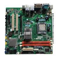
Advantech AIMB-567G2-00A1E User Manual (92 pages)
Intel LGA775 Core 2 Quad/Duo mATX Motherboard with Dual VGA/DVI/DDR3/4 COM/Dual LAN
Brand:
Advantech
| Category:
Motherboard
| Size: 9.34 MB
Table of Contents
Safety Information
2
Declaration of Conformity
4
Ordering Information
7
Table of Contents
9
Chapter 1 General Information
13
Introduction
14
Features
14
Specifications
15
System
15
Memory
15
Input/Output
15
Graphics
15
Ethernet LAN
15
Industrial Features
15
Mechanical and Environmental Specifications
15
Jumpers and Connectors
16
Table 1.1: Jumpers
16
Table 1.2: Connectors
16
Board Layout: Jumper and Connector Locations
17
Figure 1.1 Jumper and Connector Location
17
Figure 1.2 I/O Connectors
17
AIMB-567 Block Diagram
18
Figure 1.3 AIMB-567 Block Diagram
18
Safety Precautions
19
Jumper Settings
20
ATX/AT Mode Selector (PSON1)
20
Chassis Instruction Connector (JCASE1)
20
CMOS Clear (CMOS1)
20
How to Set Jumpers
20
Table 1.3: CMOS1
20
Table 1.4: ATX/AT Mode Selector (PSON1)
20
COM3 RS 232/422/485 Mode Selector (JSETCOM3)
21
Table 1.5: COM3 RS 232/422/485 Mode Selector (JSETCOM3)
21
System Memory
21
Memory Installation Procedures
21
Cache Memory
22
Processor Installation
22
Chapter 2 Connecting Peripherals
23
Introduction
24
Parallel Port (LPT1)
24
USB Ports (USB12/LAN2_USB34/USB56/USB78)
25
Table 2.1: LAN LED Indicator
25
VGA Connector (VGA1)
26
Serial Ports (COM1~COM4)
27
PS/2 Keyboard and Mouse Connector (KBMS1)
28
CPU Fan Connector (CPU_FAN1)
29
System FAN Connector (SYS_FAN1/2)
30
Front Panel Connectors (JFP1/2/3)
31
ATX Soft Power Switch (JFP1)
31
Reset Connector (JFP1)
31
External Speaker (JFP2)
32
HDD LED Connector (JFP2)
32
SM Bus Connector (JFP2 PIN 6,8)
32
Power LED and Keyboard Lock Connector
33
Lock)
33
Line out and MIC in Connector (AUDIO1)
34
Serial ATA Interface (SATA 1/2/3/4)
35
ATX Power Connector (ATX12V1, EATXPWR1)
36
SPI Flash Connector (SPI_CN1)
37
Front Panel Audio Connector (FPAUDIO1)
38
DVI Connector(DVI1)
39
Primary EIDE Connector (IDE1)
39
USB 2.0 Connector (USB 56, 78)
40
Digital Audio Connector(SPDIF_OUT1)
41
Connector to Check Chassis LED Board(VOLT1)
42
GPIO Pin Header (GPIO1)
42
BIOS Operation
43
Chapter 3 BIOS Operation
43
Introduction
44
BIOS Setup
44
Main Menu
45
Advanced BIOS Features
46
CPU Configuration
46
IDE/SATA Configuration
47
Super IO Configuration
48
Hardware Health Configuration
49
ACPI Setting
50
General ACPI Setting
50
Advanced ACPI Configuration
51
APM Configuration
51
Advanced Pci/Pnp Setting
52
Boot Setting
53
Security Setting
54
Advanced Chipset Settings
54
North Bridge Chipset Configuration
55
South Bridge Chipset Configuration
56
Exit Option
57
Chapter 4 Chipset Software Installation Utility
59
Before You Begin
60
Introduction
60
Windows Xp/Windows 7 Driver Setup
61
VGA Setup
63
Chapter 5 VGA Setup
63
Introduction
64
Windows XP/7
64
LAN Configuration
67
Chapter 6 LAN Configuration
67
Introduction
68
Features
68
Installation
68
Windows XP/ Windows 7 Setup (Intel 82583V)
68
Appendix A Programming the Watchdog Timer
71
Programming the Watchdog Timer
72
Watchdog Timer Overview
72
Table A.1: Watchdog Timer Registers
74
A.1.3 Example Program
75
Example Program
75
Appendix B I/O Pin Assignments
79
Parallel Port (LPT1)
80
Table B.1: Parallel Port (LPT1)
80
USB Header (USB56)
80
Table B.2: USB Header (USB56)
80
USB Header (USB78)
81
Table B.3: USB Header (USB78)
81
VGA Connector (VGA1)
81
Table B.4: VGA Connector (VGA1)
81
RS-232 Interface (COM1-COM4)
82
B.5 RS-232 Interface (COM1-COM4)
82
RS-232/422/485 Setting Interface (JETCOM3)
82
Table B.6: RS-232/422/485 Setting Interface (JETCOM3)
82
PS/2 Keyboard and Mouse Connector (KBMS1)
83
SPI_CN1: SPI Fresh Card Pin Connector
83
Table B.7: SPI_CN1:SPI Fresh Card Pin Connector
83
Table B.8: PS/2 Keyboard and Mouse Connector (KBMS1)
83
CPU Fan Power Connector (CPU_FAN1)
84
Table B.5: RS-232 Interface (COM1~COM2)
82
System Fan Power Connector (SYS_FAN1/SYS_FAN2)
84
Front Panel Connectors (JFP1/2)
85
Power LED & Keyboard Lock Connector (JFP3)
85
Power Switch/Hdd Led/Smbus/Speaker (JFP1/JFP2)
85
Table B.11:Power LED & Keyboard Lock Connector (JFP3)
85
ATX1 12 V Auxiliary Power Connector (ATX12V1)
86
Table B.13:ATX1 12 V Auxiliary Power Connector (ATX12V1)
86
ATX Power Connector (EATXPWR1)
86
Table B.14:ATX Power Connector (ATX2)
86
USB/LAN Ports (LAN1/2_USB12/USB34)
87
Table B.15:USB Port
87
Table B.16:Ethernet 10/100Base-T RJ-45 Port
87
Line Out, MIC in Connector (AUDIO1)
87
Serial ATA0 (SATA1)
87
Table B.17:Serial ATA0 (SATA1)
87
Serial ATA1 (SATA2)
88
Table B.18:Serial ATA1 (SATA2)
88
AT/ATX Mode (PSON1)
88
Table B.19:AT/ATX Mode (PSON1)
88
Fpaudio1(Front Panel Audio Connector)
88
Table B.20:Front Panel Audio Connector (FPAUDIO1)
88
GPIO1(GPIO Pin Header)
88
Table B.21:GPIO Pin Header(GPIO1)
88
System I/O Ports
89
B.21 System I/O Ports
89
Table B.22:GPIO Pin Header(GPIO2)
89
Table B.23:System I/O Ports
89
Jcase1(Open Case Connector)
90
Table B.24:Case Open Connector(JCASE1)
90
DMA Channel Assignments
90
Table B.25:DMA Channel Assignments
90
Interrupt Assignments
90
Table B.26:Interrupt Assignments
90
St MB Memory Map
91
Table B.27:1St MB Memory Map
91
Advertisement
Advertisement
Related Products
Advantech AIMB-567
Advantech AIMB-567VG-00A1E
Advantech AIMB-560 Series
Advantech AIMB-564
Advantech AIMB-562 KIOSK
Advantech AIMB-562 series
Advantech AIMB-560G2-00A1
Advantech AIMB-560VG-00A1
Advantech AIMB-506
Advantech AIMB-580QG2-00A1E
Advantech Categories
Motherboard
Computer Hardware
Desktop
Touch Panel
PCI Card
More Advantech Manuals
Login
Sign In
OR
Sign in with Facebook
Sign in with Google
Upload manual
Upload from disk
Upload from URL