Table of Contents
Advertisement
Advertisement
Table of Contents

Subscribe to Our Youtube Channel
Related Manuals for Advantech AIMB-581


Summary of Contents for Advantech AIMB-581
- Page 2 The documentation and the software included with this product are copyrighted 2011 by Advantech Co., Ltd. All rights are reserved. Advantech Co., Ltd. reserves the right to make improvements in the products described in this manual at any time without notice.
- Page 3 Whether your new Advantech equipment is destined for the labo- ratory or the factory floor, you can be assured that your product will provide the reliability and ease of operation for which the name Advantech has come to be known.
-
Page 4: Declaration Of Conformity
LGA1155 PASS 3.3 GHz Intel® Co e™ i5- 2400 Pr cessor SR00Q D2 5 GT/s 32nm NA NA LGA1155 PASS 3.1GHz tel® Core™ i7- 2600 Processor SR00B D2 5 GT/s 32nm NA NA LGA1155 PASS .4 GHz AIMB-581 User Manual... -
Page 5: Ordering Information
PASS 1333 HCH9 (256x8) Ordering Information Part Number Chipset Memory USB 3.0 VGA DVI1/2 LVDS USB COM TPM GbE LAN AIMB-581QG2-00A1E Non-ECC 2 1/(1) ECC/ AIMB-581WG2-00A1E C206 1/(1) Non-ECC *() means do not populated on MP version. AIMB-581 User Manual... - Page 6 It should be free of marks and scratches and in perfect working order upon receipt. As you unpack the AIMB-581, check it for signs of ship- ping damage. (For example, damaged box, scratches, dents, etc.) If it is damaged or it fails to meet the specifications, notify our service department or your local sales representative immediately.
-
Page 7: Table Of Contents
Figure 1.1 Jumper and Connector Locat on ......5 Figure 1.2 I/O Connectors ............ 6 AIMB-581 Board Diagram ..............6 Figure 1.3 AIMB-581 Board Diagram ........6 Safety Precautions ................7 Jumper Settings ...... - Page 8 Save & Exit Configuration ............... 63 Chapter Software Introduction & Service ..65 Introduction ..................... 66 Value-Added Software Services ............. 66 4.2.1 Software API................66 4.2.2 Software Utility................68 Chapter Chipset Software Installation Utility Before You Begin..................70 AIMB-581 User Manual viii...
- Page 9 Table B.13:Serial ATA 0/1 (SATA1 ~ 6) ........96 B.14 AT/ATX Mode (PSON1) ................96 Table B.14:AT/ATX Mode (PSON1) ........... 96 B.15 HD Audio Interface (FPAUD1) ..............96 Table B.15:AC-97 Audio Interface (FPAUD1)......96 B.16 GPIO Pin Header (GPIO1)..............97 AIMB-581 User Manual...
- Page 10 DMA Channel Assignments ..............100 Table B.22:DMA Channel Assignments ........100 B.23 Interrupt Assignments ..............101 Table B.23:Interrupt Assignments ........101 B.24 1st MB Memory Map................101 Table B.24:1st MB Memory Map ......... 101 AIMB-581 User Manual...
-
Page 11: Chapter 1 General Information
Chapter General Information... -
Page 13: Input/Output
USB port: Supports up to 10 USB 2.0 ports with transmission rates up to 480 Mbps and 2 USB 3.0 ports with transmission rates up to 5 Gbps. GPIO: AIMB-581 supports 8-bit GPIO from super I/O for general purpose con- trol application. 1.3.4 Graphics ... -
Page 14: Jumpers And Connectors
Jumpers and Connectors Connectors on the AIMB-581 motherboard link it to devices such as hard disk drives and a keyboard. In addition, the board has a number of jumpers used to configure your system for your application. The tables below list the function of each of the board jumpers and connectors. Later sections in this chapter give instructions on setting jumpers. -
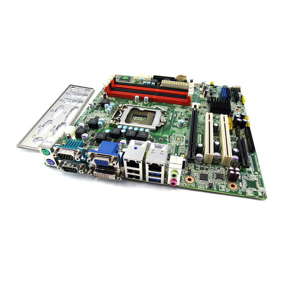
Page 16: Aimb-581 Board Diagram
Figure 1.2 I/O Connectors AIMB-581 Board Diagram Figure 1.3 AIMB-581 Board Diagram AIMB-581 User Manual... -
Page 17: Safety Precautions
1, 2, and 3. In this case you connect either pins 1 and 2, or 2 and 3. A pair of needle-nose pliers may be useful when set- ting jumpers. AIMB-581 User Manual... -
Page 21: Memory Installation Procedures
1.11 Cache Memory The AIMB-581 supports a CPU with one of the following built-in full speed L3 ca hes: 8 MB for Intel Xeon E3-1275 6 MB for Intel Xeon E3-1225... - Page 22 AIMB-581 User Manual...
-
Page 23: Connecting Peripherals
Chapter Connecting Peripherals... - Page 40 AIMB-581 User Manual...
-
Page 41: Bios Operation
Chapter BIOS Operation... -
Page 42: Introduction
AIMB-581 setup screens. BIOS Setup The AIMB-581 Series system has AMI BIOS built in, with a CMOS SETUP utility that allows users to configure required settings or to activate certain system features. The CMOS SETUP saves the configuration in the CMOS RAM of he motherboard. -
Page 43: Main Menu
System Date using the <Arrow> keys. Enter new values through the keyboard. Press the <Tab> key or the <Arrow> keys to move between fields. The date must be entered in MM/DD/YY format. The time must be entered in HH:MM:SS format. AIMB-581 User Manual... -
Page 44: Advanced Bios Fe T Res
3.3.1 Advanced BIOS Features Select the Advanced tab from the AIMB-581 setup screen to enter the Advanced BIOS Setup screen. You can select any of the items in the left frame of the screen, such as CPU Configuration, to go to the sub menu for that item. You can display an Advanced BIOS Setup option by highlighting it using the <Arrow>... -
Page 45: Acpi Setting
Enable or disable BIOS ACPI auto configuration. Make System with Fixed Time PowerOn by Modem Allows the system to be awakened from an ACPI sleep state by a wake-up sig- nal from a modem that supports wake-up function. AIMB-581 User Manual... -
Page 46: Cpu Configura Ion
Intel Virtualization Technology (Intel VT) is a set of hardware enhancements to Intel server and client platforms that provide software-based virtualization solu- tions. Intel VT allows a platform to run multiple operating systems and applications in independent partitions, allowing one computer system can function as multiple virtual systems. AIMB-581 User Manual... -
Page 47: Sata Configuration
Set to [AHCI mode] when you want the SATA hard disk drives to use the AHCI (Advanced Host Controller Interface). The AHCI allows the onboard storage r to enable advanced serial ATA features that increase storage perfor- mance on random workloads by allowing the drive to internally optimize the order of commands. AIMB-581 User Manual... -
Page 48: Intel Txt Onfiguration
3.3.5 Intel TXT Configuration Secure Mode Extension (SMX) Intel TXT Configuration This item allow you to enable o disable Intel Trusted Execution Technology AIMB-581 User Manual... -
Page 49: U B Configuration
This is just a workaround item under OS without EHCI hand-off support. Device Reset time out USB mass storage d vic start unit command time out. Mass Storage Devices Show the USB ma s storage device detail information. AIMB-581 User Manual... -
Page 50: Supe Io Configuration
3.3.7 Super IO Configuration AIMB-581 User Manual... - Page 51 Serial Port 1/2 Configuration Serial port 1/2 IRQ /IO/ mode resource configuration. Users can choose IRQ,IO and MODE. CIR Controller Configuration AIMB-581 User Manual...
- Page 52 AIMB-581 User Manual...
- Page 53 AIMB-581 User Manual...
- Page 54 This item allows users to enable or disable console redirection or Microsoft Win- dows Emergency Management Services (EMS) Out-of-Band Mgmt Port Select the port for Microsoft Windows Emergency Management Services (EMS) to allow for remote management of a Windows Server OS. AIMB-581 User Manual...
-
Page 55: W Monitor
Warning T mperature Use this t set the CPU warning temperature threshold. When the system CPU reache the warning temperature, the buzzer will beep. CPUFAN0 Mode Setting To enable or disable the smart fan control feature. AIMB-581 User Manual... -
Page 56: Ntelligent Power Sharing
3.3.9 Intelligent Power Sharing Intelligent Power Sharing This item allows you to enable o disable Intelligent Power Sharing function. 3.3.10 AMT Configuration AIMB-581 User Manual... - Page 57 AMT CIRA Timeo t OEM defined time out for MPS connection to be established. Watchdog This item allows users to enable or disable WatchDog Timer. OS Timer Sets OS Watchdog Timer. BIOS Timer Sets BIOS Watchdog timer. AIMB-581 User Manual...
- Page 58 Intel Anti-Theft Technology This item allows users to enable or disable Intel® Anti-Theft Technology (Intel? AT), which helps stop laptop the by making computers useless to thieves with immediate shut down. AIMB-581 User Manual...
- Page 59 TPM Support This item allows users to enable or disable Trusted Platform Module function. ME FW Image Re-Flash This item allows users to enable or disable Me FW image re-flash function. AIMB-581 User Manual...
-
Page 60: 3.11 Switchable Graphics
3.3.11 Switchable Graphics SG Mode Select This item allows users to select witchable graphics mode. AIMB-581 User Manual... -
Page 61: 4 Chipset Configuration Setting
Enable or disable the high precision timer. SLP_S4 Assertion Width This item allows users to set a delay of sorts. Restore AC Power Loss This item allows users to select off, on and last state. AIMB-581 User Manual... -
Page 62: North Bridge Configuration
3.4.2 North Bridge Configuration 3.4.2.1 System Agent(SA) Configuration VT-d This item allows users to enab e or disable VT-d. NB PCIe Configurati n AIMB-581 User Manual... - Page 63 This item allows users to enable or disable PEG always. PEG ASPM This item allows users to enable or disable PEG ASPM. Primary Display This item allows users to select which graphic controllers to use as the primary boot device AIMB-581 User Manual...
- Page 64 LCD Panel Type This item allows users to s lect panel resolution. Panel Scaling This item allows us rs t enable or disable panel scaling. Active LFP This item allows users to select LFP configuration. AIMB-581 User Manual...
-
Page 65: South Bridge Configuration
This item allows you to set a delay of a set number of seconds. Azalia HD Audio Enables or disables the HD Audio controller. Azalia internal HDMI codec Enables or disables the internal HDMI codec. High Precision Timer Enables or disables High Precision Event Timer (HPET) AIMB-581 User Manual... -
Page 66: Pci Express Ports Configuration
3.4.4 PCI Express Ports Configuration PCI Express Ports Configuration Disable / Enable the PCI Express ports. AIMB-581 User Manual... - Page 67 AIMB-581 User Manual...
- Page 68 AIMB-581 User Manual...
- Page 69 AIMB-581 User Manual...
-
Page 70: Usb Configuration
3.4.5 USB Configuration USB Configuration Disable / Enable the USB contro ler (EHCI #1) and (EHCI #2) and allow users to disable/ enable USB ports AIMB-581 User Manual... -
Page 71: Boot Setting
Enable/disable option for ROM to trap int 19. Boot Option Priority Boot Option #1 Boot Option #2 Show the boot device choices. Hard Drive BBS Priorities: Select the main hard disk device type to be a boot hard drive. AIMB-581 User Manual... -
Page 72: Security Setting
Select this option and press <ENTER> to access the sub menu, and then type in the password. Set the Administrator password. User Password Select this option a d press <ENTER> to access the sub menu, and then type in the password. Set the User password. AIMB-581 User Manual... -
Page 73: Save & Exit Configuration
Select Restore Defaults from the Exit menu and press <Enter>. Save as User Default Save the all current settings as a user default. Restore User Default Restore all settings to user default values. Boot Override Shows the boot device types on the system. AIMB-581 User Manual... - Page 74 AIMB-581 User Manual...
-
Page 75: Software Introduction & Service
Chapter Software Introduction & Service... -
Page 76: Introduction
Introduction The mission of Advantech Embedded Software Services is to "Enhance quality of life with Advantech platforms and Microsoft® Windows® embedded technology." We enable Windows® Embedded software products on Advantech platforms to more effectively support the embedded computing community. Customers are freed from the hassle of dealing with multiple vendors (hardware suppliers, system integrators, embedded OS distributors) for projects. - Page 77 System Throttling Refers to a series of methods for reducing power consump- tion in computers by lowering the clock frequency. This API allows the user to adjust the clock from 87.5% to 12.5%. AIMB-581 User Manual...
-
Page 78: Software Utility
The eSOS also provide for remote connection via Telnet serve and FTP server so the administrator can attempt to rescue the system. Note: This function requires BIOS cus- tomization. AIMB-581 User Manual... -
Page 79: Chipset Software Installation Utility
Chapter Chipset Software Installation Utility... -
Page 81: Windows Xp/Windows 7 Driver Setup
Windows XP/Windows 7 Driver Setup Insert the driver CD into your system's CD-ROM drive. You can see the driver folder items. Navigate to the "Chipset" folder and click "infinst_autol.exe" to complete the installation of the driver. AIMB-581 User Manual... - Page 82 AIMB-581 User Manual...
-
Page 83: Chapter 6 Vga Setup
Chapter VGA Setup... - Page 85 AIMB-581 User Manual...
- Page 86 AIMB-581 User Manual...
-
Page 87: Chapter 7 Lan Configuration
Chapter LAN Configuration... -
Page 89: Windows® 7/Xp Driver Setup (Intel 82579Lm/82583V)
Windows® 7/XP Driver Setup (Intel 82579LM/ 82583V) Insert the driver CD into your system's CD-ROM drive. Select the LAN folder then navigate to the directory for your OS. AIMB-581 User Manual... - Page 90 AIMB-581 User Manual...
- Page 91 Appendix Programming the Watchdog Timer...
-
Page 92: Appendix A Programming The Watchdog Timer
Programming the Watchdog Timer The AIMB-581's watchdog timer can be used to monitor system software operation and take corrective action if the software fails to function within the programmed period. This section describes the operation of the watchdog timer and how to pro- gram it. - Page 94 Bit 5: Write 1 to generate a timeout signal immedi- ately and automatically return to 0. [default=0] Bit 4: Read status of watchdog timer, 1 means timer is “timeout”. Write this address to I/O port 2E (hex) to lock the AA (hex) watchdog timer 2. AIMB-581 User Manual...
-
Page 95: Example Program
Mov al,10 Out dx,al ;- ------------------------------------------------------- Dec dx ; Lock NCT6776F Mov al,0aah Out dx,al Enable watchdog timer and set 5 minutes as timeout interval ;----------------------------------------------------------- Mov dx,2eh ; Unlock NCT6776F Mov al,87h Out dx,al Out dx,al AIMB-581 User Manual... - Page 96 E able watchdog timer to be reset by mouse ; ---- ----------------------------------------------------- Mov dx,2eh ; Unlock NCT6776F Mov al,87h Out dx,al Out dx,al ;----------------------------------------------------------- Mov al,07h ; Select registers of watchdog timer Out dx,al Inc dx Mov al,08h Out dx,al ;----------------------------------------------------------- AIMB-581 User Manual...
- Page 97 Mov al 30h Out dx al Inc dx Mov al,01h Out dx,al ;----------------------------------------------------------- Dec dx ; Enable watchdog timer to be strobed reset by keyboard Mov al,0f7h Out dx,al Inc dx In al,dx Or al,40h Out dx,al AIMB-581 User Manual...
- Page 98 Dec dx ; Generate a time-out signal Mov al,0f7h Out dx,al ;Write 1 to bit 5 of F7 register Inc dx In al,dx Or al,20h Out dx,al ;------ --- ---------------------------------------------- Dec dx ; Lock NCT6776F Mov al,0aah Out dx,al AIMB-581 User Manual...
-
Page 99: Appendix B I/O Pin Assignments
Appendix I/O Pin Assignments... -
Page 100: Usb Header (Usb56, Usb78,Usb9010,Usb1112)
USB Header (USB56, USB78,USB9010,USB1112) Table B.1: USB Header (USB56) Signal Signal USB0_VCC5 USB1_VCC5 USB0_D- USB1 D- USB0_D+ USB1_D+ VGA Connector (VGA1) Table B.2: VGA Connector (VGA1) Signal Signal CRT_VCCIN VGA_G VGA_B V_SDAT H-SYNC V-SYNC V_SCLK AIMB-581 User Manual... -
Page 102: Ps/2 K Yb Ard And Mouse Connector (Kbms1)
PS/2 Keyboard and Mouse Connector (KBMS1) Table B.5: PS/2 Keyboard and Mouse Connector (KBMS1) Signal KB DATA KB VCC KB CLK M_DATA M_VCC M CLK RS-232 Interface (COM3/4/5/6) AIMB-581 User Manual... -
Page 103: Cpu Fan Power Connector (Cpu_Fan1)
DCD_5 DSR_5 RXD_5 RTS 5 TXD_5 CTS_5 DTR_5 RRI_5 GND_5 GND_5 DCD_6 DSR_6 RXD_6 RTS_6 TXD_6 CTS_6 DTR_6 RRI_6 GND_6 GND_6 CPU Fan Power Connector (CPU_FAN1) Table B.7: CPU Fan Power Connector (CPU_FAN1) Signal +12V PWM DETECT AIMB-581 User Manual... -
Page 104: System Fan Power Connector (Sys_Fan1/2/3/4)
You can use an LED to indicate when the single board computer is on. Pin 1 of JFP3 supplies the LED's power, and Pin 3 is the ground Table B.9: Power LED & Keyboard Lock Connector (JFP2) Function LED power KEYLOCK# AIMB-581 User Manual... -
Page 105: Power Switch/Hdd Led/Smbus/Speaker (Jfp1)
Table B.10: Power Switch/HDD LED/SMBus/Speaker (JFP1) Signal Signal SPK_P1 HDDLED+ HDDLED- SPK_P3 SMB_DAT SYS_RST SPK_P4 SMB_CLK B.11 USB/LAN ports (LAN1_USB12/LAN2_USB34) Table B.11: USB Port Signal Signal Data0+ Data0- Table B.12: Ethernet 10/100 Mbps RJ-45 Port Signal Signal XMT+ XMT- RCV- RCV+ AIMB-581 User Manual... -
Page 106: Line In, Line Out, Mic In Connector (Audio1)
AT/ATX Mode (PSON1) Table B.14: AT/ATX Mode (PSON1) Signal Signal #PSON_SIO #PSON (to super O) (to power supply) B.15 HD Audio Interface (FPAUD1) Table B.15: AC-97 Audio Interface (FPAUD1) Signal Signal MIC2_L MIC2_R FP_AUD_DET LOUT2_R SRTN1 LOUT2_DET LOUT2_L SRTN2 AIMB-581 User Manual... -
Page 107: Gpio Pin Header (Gpio1)
Table B.16: GPIO Pin Header (GPIO1) Signal Signal GPIO0 GPIO4 GPIO1 GPIO5 GPIO2 GPIO6 GPIO3 GPIO7 B.17 LVDS Connector: LVDS1 Table B.17: LVDS1 Connector Signal Signal VDDSAFE_1 VDDSAFE_2 GND_1 GND_7 VDDSAFE_3 VDDSAFE_4 OD0- ED0- OD0+ ED0+ GND_2 GND_8 OD1- ED1- OD1+ ED1+ AIMB-581 User Manual... -
Page 108: Lvds Power Jumper (Jlvds1)
GND_6 GND_12 OD3- ED3- OD3+ ED3+ HPLG VCON B.18 LVDS Power Jumper (JLVDS1) * default setting Table B.18: LVDS Power Jumper Signal VCC3 VCC_LCD B.19 LVDS Inverter (INV1) Table B.19: LVDS Power Jumper Signal +12V BL_EN BL_CLT AIMB-581 User Manual... -
Page 109: Atx Power Connector (Atxpwr1)
B.20 ATX Power Connector (ATXPWR1) Table B.20: ATX Power Connector (ATXPWR1) Signal Signal +3.3 V 3.3 V +3.3 V -12 V +5 V PSON -5 V 5 VSB +5 V 12 V +5 V AIMB-581 User Manual... -
Page 110: Atx 12 V Connector (Atx12V1)
Table B.21: ATX 12 V connector (ATX12V1) Signal Signal aGND aGND CPU_+12V CPU_+12V B.22 DMA Channel Assignments Table B.22: DMA Channel Assignments Channel Function Available Available Floppy disk (8-bit transfer) Available Cascade for DMA controller 1 Available Available Available AIMB-581 User Manual... -
Page 111: Interrupt Assignments
1st MB Memory Map Table B.24: 1st MB Memory Map Addr. range (Hex) Device E0000h - F FFF BIOS CC000h DFFFFh Unused C0000 - CBFFFh VGA BIOS A0000h - BFFFFh Video Memory 00000h - 9FFFFh Base memory AIMB-581 User Manual...
Need help?
Do you have a question about the AIMB-581 and is the answer not in the manual?
Questions and answers