
Related Manuals for Advantech AIMB-506


Summary of Contents for Advantech AIMB-506
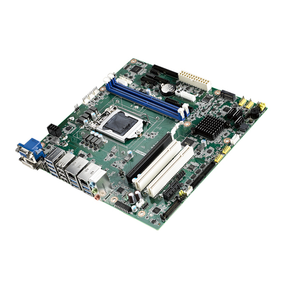
- Page 1 User Manual AIMB-506 Intel® /Core™ i7/i5/i3 /Pentium/ Celeron LGA1151 MicroATX with VGA/DVI/DP/eDP (LVDS), 14 COM, Dual LAN, DDR4, PCIe x 16, PCIe x 1, PCI x 2 and SATAIII...
- Page 2 The documentation and the software included with this product are copyrighted 2020 by Advantech Co., Ltd. All rights are reserved. Advantech Co., Ltd. reserves the right to make improvements in the products described in this manual at any time without notice.
- Page 3 Whether your new Advantech equipment is destined for the labo- ratory or the factory floor, you can be assured that your product will provide the reliability and ease of operation for which the name Advantech has come to be known.
- Page 4 Intel i3-8100T 3.1G 14nm LGA1511 Pass Intel Pentium® Processor G5400 3.7G 14nm LGA1511 Pass Intel Pentium® Processor G5400T 3.1G 14nm LGA1511 Pass Intel Celeron® Processor G4900 3.1G 14nm LGA1511 Pass Intel Celeron® Processor G4900T 2.9G 14nm LGA1511 Pass AIMB-506 User Manual...
- Page 5 Because of Advantech’s high quality-control standards and rigorous testing, most of our customers never need to use our repair service. If an Advantech product is defec- tive, it will be repaired or replaced at no charge during the warranty period. For out- of-warranty repairs, you will be billed according to the cost of replacement materials, service time and freight.
- Page 6 It should be free of marks and scratches and in perfect working order upon receipt. As you unpack the AIMB-506, check it for signs of ship- ping damage. (For example, damaged box, scratches, dents, etc.) If it is damaged or it fails to meet the specifications, notify our service department or your local sales representative immediately.
-
Page 7: Table Of Contents
Board Layout: Jumper and Connector Locations........6 Figure 1.1 Jumper and Connector Locations....... 6 Figure 1.2 I/O Connectors ............6 AIMB-506 Board Diagram ................. 7 Figure 1.3 AIMB-506 Block Diagram ........... 7 Safety Precautions ..................7 Jumper Settings ..................8 1.8.1 How to Set Jumpers.............. - Page 8 Before You Begin..................80 Introduction ..................... 80 Windows 10 Driver Setup ............... 81 Chapter VGA Setup ......... 83 Introduction ..................... 84 Windows 10 VGA Driver Installation ............84 Chapter LAN Configuration ......85 Introduction ..................... 86 Features....................86 AIMB-506 User Manual viii...
- Page 9 SPI Programming Pin Header (SPI_CN1) ..........114 B.42 SATA Connector (SATA3) ..............115 B.43 SPI ROM Socket (SPI1)................ 115 B.44 Clear CMOS Pin Header (JCMOS1)............. 115 B.45 SMbus Pin Header (SMBUS1).............. 116 B.46 USB2.0 Pin Header (USB1516) ............116 AIMB-506 User Manual...
- Page 10 B.59 Audio Amplifier Pin Header (AMP1)............127 B.60 Front Audio Pin H............eader (FPAUD1)127 B.61 LAN Active LED Pin Header (LANLED1)..........127 B.62 COM1 RI# Selection Pin Header(JSETCOM1_V1) ......128 B.63 COM2 RI# Selection Pin Header(JSETCOM2_V2) ......128 AIMB-506 User Manual...
-
Page 11: Chapter 1 General Information
Chapter General Information... -
Page 12: Introduction
Introduction AIMB-506 is designed with the Intel H310 for industrial applications that require both high-performance computing and enhanced power management capabilities. The motherboard supports 8th /9th Intel® Core™ i7/i5/i3 embedded processors up to 8 MB L3 cache and DDR4 2666 MHz up to 64GB, per slot up to 32GB. Multiple I/O connectivity of 14 serial ports, 12 USB 2.0, 8 USB 3.0, dual GbE LAN, and 3 SATA III... -
Page 13: Input/Output
USB port: Supports up to 12 USB 2.0 ports with transmission rates up to 480 Mbps and 8 USB 3.0 ports with transmission rates up to 5 Gbps. GPIO: AIMB-506 supports 16-bit GPIO from super I/O for general purpose con- trol applications. 1.3.4 Graphics ... -
Page 14: Mechanical And Environmental Specifications
Board weight: 0.365 kg Jumpers and Connectors Connectors on the AIMB-506 motherboard link it to devices such as hard disk drives and a keyboard. In addition, the board has a number of jumpers used to configure your system for your application. - Page 15 Low pin count interface (2x7 pin header) M2B1 M.2 (B Key /2242) Buzzer SPI1 SPI BIOS flash socket AMP1 Audio amplifier output connector JSMB2 SMBus header Power switch/ reset/ external speaker/ SATA HDD LED / SMBus JFP2 connector JCASE1 Case open connector AIMB-506 User Manual...
-
Page 16: Board Layout: Jumper And Connector Locations
Board Layout: Jumper and Connector Locations Figure 1.1 Jumper and Connector Locations Figure 1.2 I/O Connectors AIMB-506 User Manual... -
Page 17: Aimb-506 Board Diagram
AIMB-506 Board Diagram Figure 1.3 AIMB-506 Block Diagram Safety Precautions Warning! Always completely disconnect the power cord from chassis whenever you work with the hardware. Do not make connections while the power is on. Sensitive electronic components can be damaged by sudden power surges. -
Page 18: Jumper Settings
1.8.2 CMOS Clear (JCMOS1) The AIMB-506 motherboard contains a jumper that can erase CMOS data and reset the system BIOS information. Normally this jumper should be set with pins 1-2 closed. If you want to reset the CMOS data, set JCMOS1 to 2-3 closed for just a few seconds, and then move the jumper back to 1-2 closed. -
Page 19: Jlvds1: Lvds Panel Voltage 3.3V/ 5V/ 12V Selection
Jumper position for +5V Jumper position for +12V 1.8.4 PSON1: ATX, AT Mode Selector Table 1.5: PSON1: ATX, AT Mode Selector Closed Pins Result AT Mode 2-3* ATX Mode Default ATX Mode AT Mode 2-3 closed 1-2 closed AIMB-506 User Manual... -
Page 20: Jwdt1+Jobs1: Watchdog Timer Output, Obs Alarm Option
Table 1.6: JWDT1+JOBS1: Watchdog & Beep Pin Header Pin Name Watchdog Reset# output System Reset input# SIO Warning Beep output SP1 Buzzer Beep input Watchdog Timer Output (2-3) (Default) OBS BEEP (4-5) (Default) Watchdog Timer Disable (1-2) OSB BEEP (4-5) (Default) AIMB-506 User Manual... -
Page 21: Jsetcom3/7: Com3/7 Rs232, Rs422, Rs485 Selection
COM2_TXD485+ COM2_RXD485- RS-232 Mode (Default) (5-6) (7-9) (8-10) (13-15) (14-16) RS-422 Mode (3-4) (9-11) (10-12) (15-17) (16-18) RS-485 Mode (1-2) (9-11) (10-12) (15-17) (16-18) 1.8.7 LVDS VESA, JEIDA Format Selection Pin Header Setting: +V3.3 Setting: GND (Default) AIMB-506 User Manual... -
Page 22: Jcaseop_Sw1: Case Open Selection Pin Header
Jumper position for RI# (Default) Jumper position for +5V Jumper position for +12V System Memory AIMB-506 has four 288-pin memory sockets for 2666 MHz memory modules with maximum capacity of 64 GB (Maximum 32 GB for each DIMM). 1.10 Memory Installation Procedures To install DIMMs, first make sure the two handles of the DIMM socket are in the “open”... -
Page 23: Cache Memory
1.11 Cache Memory The AIMB-506 supports a CPU with one of the following built-in full speed L3 caches: 12MB for Intel Core i7-9700E/ i7-9700TE 12MB for Intel Core i7-8700/ i7-8700T 9MB for Intel i5-9500E/ i5-9500TE 9MB for Intel i5-8500/ i5-8500T... - Page 24 AIMB-506 User Manual...
-
Page 25: Chapter 2 Connecting Peripherals
Chapter Connecting Peripherals... -
Page 26: Introduction
USB5678/ USB9101112/ USB13141516/ USB17181920) The AIMB-506 provides up to 20 USB ports. The USB interface complies with USB Specification Rev 2.0 supporting transmission rates up to 480 Mbps and Rev 3.0 sup- ports transmission rates up to 5 Gbps and is fuse protected. The USB interface can be disabled in the system BIOS setup. -
Page 27: Vga1/Dvi-D Connector (Vga1+Dvi 1) Connector
VGA1/DVI-D Connector (VGA1+DVI 1) Connector AIMB-506 includes VGA1 and DVI interfaces that can drive conventional VGA1 and DVI displays. Pin assignments for COM1 and DVI connectors are detailed in Appen- dix B. AIMB-506 User Manual... -
Page 28: Serial Ports (Com1~Com14)
Serial Ports (COM1~COM14) AIMB-506 supports 14 serial ports. COM12, COM3-6, COM7-10, COM11-14 support RS-232. JSETCOM3/7 is used to select the RS-232/422/485 mode for COM3/7. These ports can connect to serial devices, such as a mouse or a printer, or to a com- munications network. -
Page 29: Display Ports (Dp1)
Display Ports (DP1) AIMB-506 has one external DP connector to support the Display Port panel. DP max resolution support goes to 4096 x 2304 @ 60 Hz AIMB-506 User Manual... -
Page 30: Ps/2 Keyboard And Mouse Connector (Kbms1)
6-pin mini-DIN connectors (KBMS1) support the PS/2 keyboard and PS/2 mouse by a cable P/N 1703060191 CPU Fan Connector (CPU_FAN1) If a fan is used, this connector supports cooling fans of 500 mA (6 W) or less AIMB-506 User Manual... -
Page 31: System Fan Connector (Sysfan1/2/3/4)
System FAN Connector (SYSFAN1/2/3/4) If a fan is used, this connector supports cooling fans of 500 mA (6 W) or less AIMB-506 User Manual... -
Page 32: Front Panel Connectors (Jfp1/Jfp2)
External Speaker (JFP1/SPEAKER) JFP2/SPEAKER is a 4-pin connector for an external speaker. If there is no external speaker, the AIMB-506 provides an onboard buzzer as an alternative. To enable the buzzer, set pins 7 & 10 as closed. AIMB-506 User Manual... -
Page 33: Power Led And Keyboard Lock Connector
System On Off (Windows 7) System Off Slow Flashes (Window 8) Fast flashes Slow flashes 2.10 Line Out, Mic In Connector (AUDIO1) Note! Line out supports 6W AMP out by default. AIMB-506 User Manual... -
Page 34: Serial Ata Interface (Sata1 ~ Sata3)
2.11 Serial ATA Interface (SATA1 ~ SATA3) AIMB-506 features a high performance Serial ATA III interface (up to 600 MB/s) which eases hard drive cabling with thin, space-saving cables AIMB-506 User Manual... -
Page 35: 8-Pin Alarm Board Connector (Volt1)
2.12 8-pin Alarm Board Connector (VOLT1) VOLT1 connects to the alarm board on the chassis. These alarm boards give warn- ings if a power supply or fan fails, or if the chassis overheats. AIMB-506 User Manual... -
Page 36: Atx Power Connector (Eatxpwr1, Atx12V2)
Please connect the ATX12V2 connector with the PSU ATX 12V 4- pin connector. For a fully configured system, we recommend that you use a power supply unit (PSU) that complies with ATX 12 V Specification 2.0 (or later version) and provides a minimum power of 180 W. AIMB-506 User Manual... -
Page 37: General Purpose I/O Connector (Gpio1)
2.14 General Purpose I/O Connector (GPIO1) 2.15 eDP/LVDS Connector (eDP1/LVDS) Note! LVDS is BOM option with eDP. Only G2 and F Sku default with eDP connector. AIMB-506 User Manual... -
Page 38: Edp Backlight Inverter(Inv1)
I/O module cable. Note! For motherboards with the optional HD Audio feature, we recommend that you connect a high-definition front panel audio module to this con- nector to take advantage of the motherboard's high definition audio capability. AIMB-506 User Manual... -
Page 39: Digital Audio Connector (Spdif1)
S/PDIF audio cable to this connector and the other end to the S/PDIF module. Note! The S/PDIF module should be purchased separately by end user 2.19 M.2 (B-Key/2242) (M2B1) M.2 B-key: 2242, supports SATA or USB interface AIMB-506 User Manual... -
Page 40: Smbus Header (Smbus1)
2.20 SMBUS Header (SMBUS1) AIMB-506 provides SMBUS connector for customer connection to SMBUS protocol embedded device. It can be configured to I2C by customer's request AIMB-506 User Manual... -
Page 41: Bios Operation
Chapter BIOS Operation... -
Page 42: Introduction
BIOS Setup The AIMB-506 Series system has AMI BIOS built in, with a SETUP utility that allows users to configure required settings or to activate certain system features. The SETUP saves the configuration in the FLASH of the motherboard. When the power is turned off, the battery on the board supplies the necessary power to pre- serve the FLASH. -
Page 43: Main Menu
System Date using the <Arrow> keys. Enter new values through the keyboard. Press the <Tab> key or the <Arrow> keys to move between fields. The date must be entered in MM/DD/YY format. The time must be entered in HH:MM:SS format. AIMB-506 User Manual... -
Page 44: Advanced Bios Features
3.2.2 Advanced BIOS Features Select the Advanced tab from the AIMB-506 setup screen to enter the Advanced BIOS Setup screen. You can select any of the items in the left frame of the screen, such as CPU Configuration, to go to the sub menu for that item. You can display an Advanced BIOS Setup option by highlighting it using the <Arrow>... - Page 45 3.2.2.1 CPU Configuration The item shows you CPU specification and feature, the content would be different for different CPU. AIMB-506 User Manual...
- Page 46 3.2.2.2 PCH FW Configuration AIMB-506 User Manual...
- Page 47 Firmware Update Configuration ME FW Image Re-Flash [Disabled] Local FW Update [Enabled] AIMB-506 User Manual...
- Page 48 Security Device Support [Disable] Note! TCG EFI Protocol and INT1A interface won't be available AIMB-506 User Manual...
- Page 49 Select ACPI sleep state the system will enter when the SUSPEND button is pressed Lock Legacy Resources [Disabled] Enables or Disables Lock of Legacy Resources S3 Video Repost [Disabled] Enable or Disable S3 Video Repost AIMB-506 User Manual...
- Page 50 NCT6116D Super I/O Configuration Super I/O Chip [NCT6116D] Serial Port 1 Configuration – Serial Port [Enabled] – Device Settings: I/O=3F8h; IRQ =4 – Change Settings [Auto] To select an optimal setting for serial port 1. AIMB-506 User Manual...
- Page 51 Serial Port 2 Configuration – Serial Port [Enabled] – Device Settings: I/O=2F8h; IRQ =3 – Change Settings [Auto] To select an optimal setting for serial port 2. Serial Port 3 Configuration – Serial Port [Enabled] AIMB-506 User Manual...
- Page 52 To select an optimal setting for serial port 3. Serial Port 4 Configuration – Serial Port [Enabled] – Device Settings: I/O=2E8h; IRQ =7 – Change Settings [Auto] To select an optimal setting for serial port 4. AIMB-506 User Manual...
- Page 53 Serial Port 5 Configuration – Serial Port [Enabled] – Device Settings: I/O=280h; IRQ =7 – Change Settings [Auto] To select an optimal setting for serial port 5. AIMB-506 User Manual...
- Page 54 Serial Port 6 Configuration – Serial Port [Enabled] – Device Settings: I/O=288h; IRQ =7 – Change Settings [Auto] To select an optimal setting for serial port 6. AIMB-506 User Manual...
- Page 55 – ACPI Shutdown Temperature [Disabled] Use this to set the ACPI shutdown temperature threshold. When the system reaches the shutdown temperature, it will be automatically shut down by ACPI OS to protect the system from overheating damage. AIMB-506 User Manual...
- Page 56 CPU FAN Mode [SMART FAN IV Mode] The item shows you CPU temperature and fan speed (PWM) information. – SYSFAN Mode [SMART FAN IV Mode] The item shows you system temperature and fan speed (PWM) information. Digital I/O Configuration AIMB-506 User Manual...
- Page 57 – Digital I/O Pin 1 - 16 [Input] 3.2.2.7 NCT5114DSEC Super I/O Configuration Serial Port 7 Configuration – Serial Port [Enabled] – Device Settings: I/O=240h; IRQ =5 – Change Settings [Auto] AIMB-506 User Manual...
- Page 58 To select an optimal setting for serial port 7. Serial Port 8 Configuration – Serial Port [Enabled] – Device Settings: I/O=248h; IRQ =5 – Change Settings [Auto] To select an optimal setting for serial port 8. AIMB-506 User Manual...
- Page 59 Serial Port 9 Configuration – Serial Port [Enabled] – Device Settings: I/O=250h; IRQ =5 – Change Settings [Auto] To select an optimal setting for serial port 9. Serial Port 10 Configuration AIMB-506 User Manual...
- Page 60 – Serial Port [Enabled] – Device Settings: I/O=258h; IRQ =5 – Change Settings [Auto] To select an optimal setting for serial port 10. 3.2.2.8 NCT5114DTRD Super I/O Configuration Serial Port 11 Configuration AIMB-506 User Manual...
- Page 61 To select an optimal setting for serial port 11. Serial Port 12 Configuration – Serial Port [Enabled] – Device Settings: I/O=268h; IRQ =15 – Change Settings [Auto] To select an optimal setting for serial port 12. AIMB-506 User Manual...
- Page 62 Serial Port 13 Configuration – Serial Port [Enabled] – Device Settings: I/O=270h; IRQ =15 – Change Settings [Auto] To select an optimal setting for serial port 13. AIMB-506 User Manual...
- Page 63 Serial Port [Enabled] – Device Settings: I/O=278h; IRQ =15 – Change Settings [Auto] To select an optimal setting for serial port 14. 3.2.2.9 S5RTC Wake Settings The item allows you enable or disable system wake up on alarm event. AIMB-506 User Manual...
- Page 64 Wake system with Fixed Time [ Disabled ] Note! When enabled, system will wake up on the specified time 3.2.2.10 Serial Port Console Redirection Console Redirection [Disabled] Enable or disable the console redirection feature AIMB-506 User Manual...
- Page 65 XHCI Hand-off [Enabled] USB Mass Storage Driver Support [Enabled] USB hardware delays and time-outs USB Device transfer & reset time-out and delay setting. Mass Storage Devices [Auto] Shows USB mass storage device information. AIMB-506 User Manual...
- Page 66 1. Re-install your OS as UEFI Mode 2. Change all of settings above as " Legacy" * Boot option filter-> Legacy Only * Network -> Legacy * Storage -> Legacy * Video -> Legacy * Other PCI devices -> Legacy AIMB-506 User Manual...
- Page 67 3.2.2.13 Network Stack Configuration [Disabled] Enable/Disable UEFI Network Stack Note! When network stack [enable], item must enable: LANx PXE OpROM [enable] AIMB-506 User Manual...
-
Page 68: Chipset Configuration Settings
Users can display a Chipset Setup option by highlighting it using the <Arrow> keys. All Chipset Setup options are described in this section. The Chipset Setup screens are shown below. The sub menus are described on the following pages. AIMB-506 User Manual... -
Page 69: System Agent (Sa) Configuration
3.3.1 System Agent (SA) Configuration VT-d [Enabled] Disable or enable VT-d function on MCH. 3.3.1.1 Memory Configuration AIMB-506 User Manual... - Page 70 MMIO length of installed graphic controller. Retrain on Fast Fall [Enabled] Enable or disable Retrain on Fast Fall. Memory Remap [Enabled] Enable or disable Memory remap. Fast Boot [Enabled] Enable or disable Fast Boot support AIMB-506 User Manual...
- Page 71 Select DVMT5.0 Total Graphic Memory size used by the Internal Graphics Device. Note! When BIOS set as " Auto", only a single display works under DOS. Note! The dual display can only work under Windows 10, cannot work under DOS. AIMB-506 User Manual...
- Page 72 Below is the display combination table, all of these combinations are verified. Display Combination List BIOS WES 8 Single Display PASS PASS PASS PASS PASS PASS PASS PASS PASS EDP/LVDS PASS PASS PASS Dual Display VGA+DVI PASS VGA+EDP/LVDS PASS VGA+DP PASS DVI+DP PASS DVI+EDP/LVDS PASS DP+EDP/LVDS PASS AIMB-506 User Manual...
- Page 73 3.3.1.3 DMI Configuration DMI MAx Link Speed [Auto] AIMB-506 User Manual...
- Page 74 Root Port Preset Value Per lane for Gen3 Equalization. PEG Gen3 Endpoint Preset Value for each Lane Endpoint Preset Value Per lane for Gen3 Equalization. PEG Gen3 Endpoint Hint Value each Lane Endpoint Hint Value Per lane for Gen3 Equalization. AIMB-506 User Manual...
-
Page 75: Pch-Io Configuration
Enable or disable PCIE to wake the system from S5. High Precision Timer Enable or Disable High Precision Timer. State After G3 [Power Off] This item allows users to select off, on and last state. AIMB-506 User Manual... - Page 76 3.3.2.1 PCI Express Configuration PCI Express Clock Gating [Enabled] Enable or Disable PCI Express clock gating for each port. PCIe-USB Glitch W/A [Disabled] PCIe-USB Glitch W/A for bad USB device(s) connected behind PCIE/PEG Port. AIMB-506 User Manual...
- Page 77 Set the ASPM Level: Force L0s - Force all links to L0s State : AUTO - BIOS auto configure : DISABLE - Disables ASPM – L1 Substates PCI Express L1 Substates settings. – PCIe Speed [Auto] Select PCI Express port speed. AIMB-506 User Manual...
- Page 78 Set the ASPM Level: Force L0s - Force all links to L0s State : AUTO - BIOS auto configure : DISABLE - Disables ASPM – L1 Substates PCI Express L1 Substates settings. PCIe Speed [Auto] Select PCI Express port speed. AIMB-506 User Manual...
- Page 79 Set the ASPM Level: Force L0s - Force all links to L0s State : AUTO - BIOS auto configure : DISABLE - Disables ASPM – L1 Substates PCI Express L1 Substates settings. – PCIe Speed [Auto] Select PCI Express port speed. AIMB-506 User Manual...
- Page 80 3.3.2.2 SATA and RST Configuration AIMB-506 User Manual...
-
Page 81: Security Settings
Select this option and press <ENTER> to access the sub menu, and then type in the password. Set the Administrator password. User Password Select this option and press <ENTER> to access the sub menu, and then type in the password. Set the User Password. AIMB-506 User Manual... -
Page 82: Boot Settings
Quiet Boot [ Disabled ] If this option is set to disabled, the BIOS displays normal POST messages. If enabled, an OEM logo is shown instead of POST messages. Boot Option #1/#2 Choose boot priority from boot device AIMB-506 User Manual... -
Page 83: Save & Exit Configuration
Select Exit Saving Changes from the Exit menu and press <Enter>. The fol- lowing message appears: Save Configuration Changes and Exit Now? [Ok] [Cancel] Select Ok or cancel. Discard Changes and Reset Select this option to quit Setup without making any permanent changes to the system configuration. AIMB-506 User Manual... - Page 84 Defaults if the user's computer is experiencing system configuration problems. Select Restore Defaults from the Exit menu and press <Enter>. Save as User Default Save the all current settings as a user default. Restore User Default Restore all settings to user default values. AIMB-506 User Manual...
-
Page 85: Software Introduction & Services
Chapter Software Introduction & Services... -
Page 86: Introduction
Introduction The mission of Advantech Embedded Software Services is to "Enhance quality of life with Advantech platforms and Microsoft® Windows® embedded technology." We enable Windows® Embedded software products on Advantech platforms to more effectively support the embedded computing community. Customers are freed from the hassle of dealing with multiple vendors (hardware suppliers, system integrators, embedded OS distributors) for projects. - Page 87 System Throttling Refers to a series of methods for reducing power consump- tion in computers by lowering the clock frequency. This API allows the user to adjust the clock from 87.5% to 12.5%. AIMB-506 User Manual...
-
Page 88: Software Utility
Monitoring is a utility for customers to monitor system health, like voltage, CPU and system temperature and fan speed. These items are important to a device, if critical errors occur and are not solved immediately, permanent damage may be caused. AIMB-506 User Manual... -
Page 89: Chipset Software Installation Utility
Chapter Chipset Software Installation Utility... -
Page 90: Before You Begin
Before You Begin To facilitate the installation of the enhanced display drivers and utility software, read the instructions in this chapter carefully. The drivers for AIMB-506 are located on Advantech website. (http://support.advantech.com/Support/.) Updates are provided via Service Packs from Microsoft*. -
Page 91: Windows 10 Driver Setup
Windows 10 Driver Setup When enter the website of Advantech, then search product AIMB-506. There is "Chipset" driver inside. AIMB-506 User Manual... - Page 92 AIMB-506 User Manual...
-
Page 93: Vga Setup
Chapter VGA Setup... -
Page 94: Introduction
Before installing this driver, make sure the CSI utility has been installed in your system. See Chapter 5 for information on installing the CSI utility. Enter the Advantech website, then search product AIMB-506. There are "Graphic" drivers available. AIMB-506 User Manual... -
Page 95: Lan Configuration
Chapter LAN Configuration... -
Page 96: Introduction
Introduction The AIMB-506 has dual Gigabit Ethernet LANs via dedicated PCI Express x1 lanes (Realtek 8111G) that offer bandwidth of up to 500 MB/sec, eliminating the bottleneck of network data flow and incorporating Gigabit Ethernet at 1000 Mbps. Features ... -
Page 97: Windows® 10 Driver Setup (Realtek 8111G)
Windows® 10 Driver Setup (Realtek 8111G) Enter the Advantech website, then search product AIMB-506. There is "LAN" driver inside. AIMB-506 User Manual... - Page 98 AIMB-506 User Manual...
- Page 99 Appendix Programming the Watchdog Timer...
-
Page 100: Appendix A Programming The Watchdog Timer
Programming the Watchdog Timer AIMB-506's watchdog timer can be used to monitor system software operation and take corrective action if the software fails to function within the programmed period. This section describes the operation of the watchdog timer and how to program it. - Page 101 Unlock NCT6116D Select register of watchdog timer Enable the function of the watchdog timer Use the function of the watchdog timer Lock NCT6116D AIMB-506 User Manual...
- Page 102 Bit 5: Write 1 to generate a timeout signal immedi- ately and automatically return to 0. [default=0] Bit 4: Read status of watchdog timer, 1 means timer is “timeout”. Write this address to I/O port 2E (hex) to lock the AA (hex) ----- watchdog timer 2. AIMB-506 User Manual...
-
Page 103: Example Program
Inc dx Mov al,10 Out dx,al ;----------------------------------------------------------- Dec dx ; Lock NCT6779D Mov al,0aah Out dx,al Enable watchdog timer and set 5 minutes as timeout interval ;----------------------------------------------------------- Mov dx,2eh ; Unlock NCT6779D Mov al,87h Out dx,al Out dx,al AIMB-506 User Manual... - Page 104 Enable watchdog timer to be reset by mouse ;----------------------------------------------------------- Mov dx,2eh ; Unlock NCT6779D Mov al,87h Out dx,al Out dx,al ;----------------------------------------------------------- Mov al,07h ; Select registers of watchdog timer Out dx,al Inc dx Mov al,08h Out dx,al ;----------------------------------------------------------- AIMB-506 User Manual...
- Page 105 Dec dx ; Enable the function of watchdog timer Mov al,30h Out dx,al Inc dx Mov al,01h Out dx,al ;----------------------------------------------------------- Dec dx ; Enable watchdog timer to be strobed reset by keyboard Mov al,0f7h Out dx,al Inc dx In al,dx Or al,40h Out dx,al AIMB-506 User Manual...
- Page 106 Dec dx ; Generate a time-out signal Mov al,0f7h Out dx,al ;Write 1 to bit 5 of F7 register Inc dx In al,dx Or al,20h Out dx,al ;----------------------------------------------------------- Dec dx ; Lock NCT6779D Mov al,0aah Out dx,al AIMB-506 User Manual...
-
Page 107: Appendix B Pin Assignments
Appendix Pin Assignments... -
Page 108: Hd Audio Interface (Audio1)
MIC IN LINE OUT LINE IN LAN & USB3.0 Connector (LAN2_USB34) Signal Signal LAN2_VCT LAN2_MDI3+ LAN2_MDI0+ LAN2_MDI3- LAN1_MDI0- LAN2_MDI1+ LAN2_ACT LAN2_MDI1- +V3.3_LAN2 LAN2_MDI2+ LAN2_LED1_1G# LAN2_MDI2- LAN2_LED2_100M# Signal Signal +USBV2 +USBV2 RX-3 RX-4 RX+3 RX+4 TX-3 TX-4 TX+3 TX+4 AIMB-506 User Manual... -
Page 109: Lan & Usb3.0 Connector (Lan1_Usb12)
LAN & USB3.0 Connector (LAN1_USB12) Signal Signal LAN1_VCT LAN1_MDI3+ LAN1_MDI0+ LAN1_MDI3- LAN1_MDI0- LAN1_MDI1+ LAN1_ACT LAN1_MDI1- +V3.3_LAN1 LAN1_MDI2+ LAN1_LED1_1G# LAN1_MDI2- LAN1_LED2_100M# Signal Signal +USBV1 +USBV1 RX-1 RX-2 RX+1 RX+2 TX-1 TX-2 TX+1 TX+2 AIMB-506 User Manual... -
Page 110: Usb2.0 Connector (Usb5678)
USB_CM_N6 USB_CM_N8 USB_CM_P6 USB_CM_P8 USB3.0 Connector (USB9101112) Signal Signal +USBV5 +USBV6 USBPCIE_z_P1- USBPCIE_z_P3- USBPCIE_z_P1+ USBPCIE_z_P3+ USB3D1_z_RX- USB3D3_z_RX- USB3D1_z_RX+ USB3D3_z_RX+ USB3D1_z_TX- USB3D3_z_TX- USB3D1_z_TX+ USB3D3_z_TX+ +USBV5 +USBV6 USBPCIE_z_P2- USBPCIE_z_P4- USBPCIE_z_P2+ USBPCIE_z_P4+ USB3D2_z_RX- USB3D4_z_RX- USB3D2_z_RX+ USB3D4_z_RX+ USB3D2_z_TX- USB3D4_z_TX- USB3D2_z_TX+ USB3D4_z_TX+ AIMB-506 User Manual... -
Page 111: Display Port Connector (Dp1)
Display Port Connector (DP1) Signal Signal DP1_0+ DP1_3- DP1_0- DP1_AUX_EN# DP1_1+ DP1_AUX+ DP1_1- DP1_2+ DP1_AUX- DP1_HPD DP1_2- DP1_3+ +V3.3_DP1 VGA & DVI Connector (VGA1+DVI1) Signal Signal DVI1_D0- DVI1_D0+ +VCC_TMDS DVI1_HPD DVI1_D2- DVI1_SCL DVI1_D2+ DVI1_SDA DVI1_D1- DVI1_D1+ DVI1_D3- DVI1_D3+ AIMB-506 User Manual... -
Page 112: Atx 4/8 Pin Main Power Connector (Atx12V1 / Atx12V2)
Signal Signal VGA1_b_R +VCC_TMDS VGA1_b_G VGA1_b_B CLKREQ# VGA1_a_DDAT VGA1_b_HS VGA1_FOC_ON VGA1_b_VS VGA1_a_DCLK ATX 4/8 Pin Main Power Connector (ATX12V1 / ATX12V2) ATX12V1 Signal Signal +12V +12V ATX12V2 Signal Signal +12V +12V +12V +12V AIMB-506 User Manual... -
Page 113: Cpu Socket Lga 1151 H4 (Cpu1)
CPU Socket LGA 1151 H4 (CPU1) B.10 SMBUS Header (JSMB2) Signal Signal CPU_SDA CPU_SCL B.11 CPU FAN Header (CPUFAN1) Signal Signal CPU FAN SPEED CPU FAN VCC CPU FAN PWM AIMB-506 User Manual... -
Page 114: System Fan Header (Sysfan1)
SYSTEM FAN VCC SYSTEM FAN PWM B.14 DDR4 DIMM Socket (DIMMA1) Please see JEDEC STANDARD. B.15 DDR4 DIMM Socket (DIMMB1) Please see JEDEC STANDARD. B.16 Case Open Switch Pin Header (JCASEOP_SW1) Signal Signal Normal Open Normal Close Advantech define AIMB-506 User Manual... -
Page 115: Case Open Pin Header (Jcase1)
KB_CLK# KB_DAT# +V5_DUAL MS_CLK# MS_DAT# B.19 SYSTEM FAN Header (SYSFAN3) Signal Signal SYSTEM FAN SPEED SYSTEM FAN VCC SYSTEM FAN PWM B.20 SYSTEM FAN Header (SYSFAN4) Signal Signal SYSTEM FAN SPEED SYSTEM FAN VCC SYSTEM FAN PWM AIMB-506 User Manual... -
Page 116: Com Port Pin Header (Com12)
COM Port Pin Header (COM12) Signal Signal COM1_DCD# COM2_DCD# COM1_DSR# COM2_DSR# COM1_SIN COM2_SIN COM1_RTS# COM2_RTS# COM1_SOUT COM2_SOUT COM1_CTS# COM2_CTS# COM1_DTR# COM2_DTR# COM1_RI_V# COM2_RI_V# B.22 LPC Pin Header (LPC1) Signal Signal CLK (24MHz) RESET# SMB CLK SERIRQ FRAME# SMB DAT +3.3V +V5_DUAL AIMB-506 User Manual... -
Page 117: Com3456 Setting Pin Header (Jsetcom3)
COM_RXD485+ RXDRS422 UART_SIN RXDRS232 COM_SIN COM_DTR# SOUT COM_TXD485+ DCD# COM_RXD485- B.24 General Purpose I/O Pin Header (GPIO1) Signal Signal GPIO0 GPIO5 GPIO8 GPIO13 GPIO1 GPIO6 GPIO9 GPIO14 GPIO2 GPIO7 GPIO10 GPIO15 GPIO3 +V5_DUAL GPIO11 GPIO4 +V5_DUAL GPIO12 AIMB-506 User Manual... -
Page 118: Com Port Pin Header (Com3456)
DSR# [5] RXD [5] RST# [5] TXD [5] CTS# [5] DTR# [5] RI# [5] DCD# [6] DSR# [6] RXD [6] RST# [6] TXD [6] CTS# [6] DTR# [6] RI# [6] B.26 Battery Holder (BAT1) Signal Signal VBAT AIMB-506 User Manual... -
Page 119: At/Atx Mode Selection Header (Pson1)
AT/ATX Mode Selection Header (PSON1) Signal Signal +3.3V B.28 Alarm Board/CMM Power Pin Header (VOLT1) Signal Signal +5VSB +3.3V -12V +12V B.29 ATX Power Header (EATXPWR1) Signal Signal +3.3V +3.3V +3.3V -12V PSON# PWROK +5VSB +12V +12V +3.3V AIMB-506 User Manual... -
Page 120: Com Port Pin Header (Com11121314)
RST# [13] TXD [13] CTS# [13] DTR# [13] RI# [13] DCD# [14] DSR# [14] RXD [14] RST# [14] TXD [14] CTS# [14] DTR# [14] RI# [14] B.31 SIM Card Holder (SIM1) Signal Signal UIM_PWR UIM_RESET UIM_VPP UIM_CLK UIM_DATA AIMB-506 User Manual... -
Page 121: M.2 B Key Socket (M2B1)
Connector KEY Connector KEY Connector KEY Connector KEY Connector KEY Connector KEY CONFIG_0 PCIE_WAKE# M.2_GNSS_DISABLE# UIM-RESET (I) UIM-CLK (I) UIM-DATA (I/O) UIM-PWR (I) SATA_DEVSLP (O) M.2_ISH_SCL SATA_B+ M.2_ISH_SDA SATA_B- SATA_A- SATA_A+ RESET# SUSCLK(32kHz) CONFIG_1 +3.3V +3.3V +3.3V CONFIG_2 AIMB-506 User Manual... -
Page 122: Sata Connector (Sata1)
B.33 SATA Connector (SATA1) Signal Signal B.34 SATA Connector (SATA2) Signal Signal B.35 USB2.0 Pin Header (USB1920) Signal Signal VBUS VBUS USBPCIE_z_P3_b- USBPCIE_z_P4_b- USBPCIE_z_P3_b+ USBPCIE_z_P4_b+ AIMB-506 User Manual... -
Page 123: Usb2.0 Pin Header (Usb1718)
Power Button+ SPK_P2 HDD LED- Power Button- SPK_P3 SMB_DATA System Reset+ SPK_P4 SMB_CLK System Reset- B.38 Watchdog & Beep Pin Header (JWDT1+JOBS1) Signal Watch Dog Reset# output System Reset input# SIO Warning Beep output SP1 Buzzer Beep input AIMB-506 User Manual... -
Page 124: Speaker (Sp1)
B.39 Speaker (SP1) B.40 PLED Pin Header (JFP2) Signal LED Power SIO_SUSLED Keyboard Lock B.41 SPI Programming Pin Header (SPI_CN1) Signal Signal +V3.3_SPI SCLK MISO MOSI AIMB-506 User Manual... -
Page 125: Sata Connector (Sata3)
B.42 SATA Connector (SATA3) Signal Signal B.43 SPI ROM Socket (SPI1) Signal Signal MOSI MISO SCLK WP# / IO2 HOLD# / IO3 +V3.3_SPI B.44 Clear CMOS Pin Header (JCMOS1) Signal VBAT RTC RESET# AIMB-506 User Manual... -
Page 126: Smbus Pin Header (Smbus1)
B.45 SMbus Pin Header (SMBUS1) Signal +5VSB SMB CLK SMB DAT B.46 USB2.0 Pin Header (USB1516) Signal Signal VBUS VBUS USB_HCM_N3 USB_HCM_N4 USB_HCM_P3 USB_HCM_P4 B.47 USB2.0 Pin Header (USB1314) Signal Signal VBUS VBUS USB_HCM_N1 USB_HCM_N2 USB_HCM_P1 USB_HCM_P2 AIMB-506 User Manual... -
Page 127: Com Port Pin Header (Com78910)
CTS# [8] DTR# [8] RI# [8] DCD# [9] DSR# [9] RXD [9] RST# [9] TXD [9] CTS# [9] DTR# [9] RI# [9] DCD# [10] DSR# [11] RXD [10] RST# [10] TXD [10] CTS# [10] DTR# [10] RI# [10] AIMB-506 User Manual... -
Page 128: Pcie X16 Slot (Pciex16_1)
PWRGD Reserved REFCLK+ TX0+ REFCLK- TX0- RX0+ Advantech define RX0- Advantech define TX1+ Reserved TX1- RX1+ RX1- TX2+ TX2- RX2+ RX2- TX3+ TX3- RX3+ Reserved RX3- Reserved Reserved TX4+ Reserved TX4- RX4+ RX4- TX5+ TX5- RX5+ RX5- AIMB-506 User Manual... -
Page 129: Pci Slot (Pci1)
PCI Slot (PCI1) Signal Signal -12V TRST# +12V INT#A INT#B INT#C INT#D CLK33M_PCI2 GNT#1 PCI_REQ#1 CLK33M_PCI3 GNT#2 PCI_REQ#2 +V3.3_DUAL RST# CLK33M_PCI1 GNT#0 PCI_REQ#0 PME# AD31 AD30 AD29 +V3.3 AD28 AD27 AD26 AD25 +V3.3 AD24 PCI_CBE#3 AD16 AD23 +V3.3 AD22 AIMB-506 User Manual... - Page 130 AD21 AD20 AD19 +V3.3 AD18 AD17 AD16 PCI_CBE#2 +V3.3 FRAME# IRDY# +V3.3 TRDY# DEVSEL# STOP# LOCK# +V3.3 PERR# SMBCLK +V3.3 SMBDATA SERR# +V3.3 CBE#1 AD15 AD14 +V3.3 AD13 AD12 AD11 AD10 CBE#0 +V3.3 +V3.3 ACK64# #PCI1_REQ64 AIMB-506 User Manual...
-
Page 131: Pci Slot (Pci2)
INT#C +V3.3_DUAL RST# CLK33M_PCI GNT#3 PCI_REQ#3 PME# AD31 AD30 AD29 +V3.3 AD28 AD27 AD26 AD25 +V3.3 AD24 PCI_CBE#3 AD19 AD23 +V3.3 AD22 AD21 AD20 AD19 +V3.3 AD18 AD17 AD16 PCI_CBE#2 +V3.3 FRAME# IRDY# +V3.3 TRDY# DEVSEL# STOP# AIMB-506 User Manual... -
Page 132: Com78910 Setting Pin Header (Jsetcom7)
CBE#0 +V3.3 +V3.3 ACK64# #PCI1_REQ64 B.52 COM78910 Setting Pin Header (JSETCOM7) Signal Signal UART_SIN [7] RXD_RS485 UART_SIN [7] RXD_RS422 UART_SIN [7] RXD_RS232 DCDA SOUT [7] COM7_DCD# COM7_SOUT COM7_TXD485- COM7_RXD485+ SIN [7] DTR [7] COM7_SIN COM7_DTR# COM7_TXD485+ COM7_RXD485- AIMB-506 User Manual... -
Page 133: Lvds/Edp Backlight Inverter Power Header (Inv1)
B.53 LVDS/eDP Backlight Inverter Power Header (INV1) Signal +12V Inv12 BKL EN BKL CTRL B.54 LVDS Panel Voltage Selection Header (JLVDS1) Signal Signal +12V EDP1 VDD +3.3V AIMB-506 User Manual... -
Page 134: Pcie X1 Slot (Pciex1_1)
B.55 PCIe x1 Slot (PCIEX1_1) Signal Signal +12V PRSNT1# +12V +12V +12V +12V SMB_CLK Reserved SMB_DATA Reserved Reserved +3.3V Reserved Reserved +3.3V +3.3VAUX +3.3V WAKE# PWRGD Reserved REFCLK+ TX0+ REFCLK- TX0- RX0+ PRSNT2# RX0- AIMB-506 User Manual... -
Page 135: Lvds/Edp Panel Header (Lvds_Edp1)
For LVDS(Low-voltage differential signaling interface) Signal Signal A2P(EDP_CPU_TXP0) DET# CLK1N(EDP_CPU_TXN3) CLK2N A0N(EDP_CPU_TXN2) 27 CLK1P(EDP_CPU_TXP3) CLK2P A0P(EDP_CPU_TXP2) 29 A1N(EDP_CPU_TXN1) 33 GND(EDP_CH7511_HPD) A1P(EDP_CPU_TXP1) 35 A2N(EDP_CPU_TXN0) 39 ENBKL VCON For eDP(Embedded displayport) Signal Signal A2P(EDP_CPU_TXP0) CLK1N(EDP_CPU_TXN3) A0N(EDP_CPU_TXN2) 27 CLK1P(EDP_CPU_TXP3) A0P(EDP_CPU_TXP2) 29 AIMB-506 User Manual... -
Page 136: Lvds Vesa, Jeida Format Selection Pin Header (Jlvds_Vcon1)
SCD (EDP_AUX+) SDD (EDP_AUX-) A1N(EDP_CPU_TXN1) 33 GND(EDP_CH7511_HPD) A1P(EDP_CPU_TXP1) 35 A2N(EDP_CPU_TXN0) 39 B.57 LVDS VESA, JEIDA Format Selection Pin Header (JLVDS_VCON1) Signal +3.3V OPTION B.58 SPDIF Pin Header (SPDIF1) Signal SPDIF OUT AIMB-506 User Manual... -
Page 137: Audio Amplifier Pin Header (Amp1)
Front Audio Pin Header (FPAUD1) Signal Signal MIC IN-L MIC IN-R FPAUD_DETECT# LINE OUT-R SENSE R1 SENSE LINE OUT-L SENSE R2 B.61 LAN Active LED Pin Header (LANLED1) Signal Signal LAN1_ACT# LAN2 _ACT# LAN LED PWR LAN LED PWR AIMB-506 User Manual... - Page 138 B.62 COM1 RI# Selection Pin Header(JSETCOM1_V1) Signal Signal RI# [1] Advantech define Advantech define +12V Advantech define B.63 COM2 RI# Selection Pin Header(JSETCOM2_V2) Signal Signal RI# [2] Advantech define Advantech define +12V Advantech define AIMB-506 User Manual...
- Page 139 AIMB-506 User Manual...
- Page 140 No part of this publication may be reproduced in any form or by any means, electronic, photocopying, recording or otherwise, without prior written permis- sion of the publisher. All brand and product names are trademarks or registered trademarks of their respective companies. © Advantech Co., Ltd. 2020...
Need help?
Do you have a question about the AIMB-506 and is the answer not in the manual?
Questions and answers