
Related Manuals for Xantrex XT 7-6


Summary of Contents for Xantrex XT 7-6
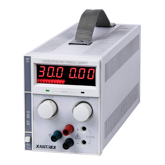
- Page 1 XT 7-6 XT 15-4 XT 20-3 XT 30-2 XT 60-1 XT 120-0.5 XT 250-0.25 Operating Manual XT 60 Watt Series Programmable DC Power Supply...
- Page 3 Operating Manual for XT Series Programmable DC Power Supply...
- Page 4 What will Xantrex do? Xantrex will, at its option, repair or replace the defective product free of charge, provided that you notify Xantrex of the product defect within the Warranty Period, and provided that Xantrex through inspection establishes the existence of such a defect and that it is covered by this Limited Warranty.
- Page 5 Xantrex or its authorized service centers (hereafter “ASCs”);...
- Page 6 APPLICABLE LAW TO APPLY TO THE PRODUCT SHALL BE LIMITED IN DURATION TO THE PERIOD STIPULATED UNDER THIS LIMITED WARRANTY. IN NO EVENT WILL XANTREX BE LIABLE FOR ANY SPECIAL, DIRECT, INDIRECT, INCIDENTAL OR CONSEQUENTIAL DAMAGES, LOSSES, COSTS OR EXPENSES...
- Page 7 Please refer to your product user manual for limitations on uses of the product. Specifically, please note that this power supply is not intended for use in connection Limitations with life support systems and Xantrex makes no warranty or representation in on Use connection with any use of the product for such purposes.
- Page 8 Warnings Warnings and cautions are defined and formatted in this manual as shown below. Cautions WARNING Describes a potential hazard which could result in injury or death, or, a procedure which, if not performed correctly, could result in injury or death. CAUTION Describes a procedure which, if not performed correctly, could result in damage to data, equipment, or systems.
-
Page 9: About This Manual
About This Manual This Operating Manual contains operation instructions for the Series of high performance, switching, laboratory power supplies, available in several voltage models at 60 watts. It provides information on features and specifications, installation procedures, and basic functions testing, as well as operating procedures for using both standard and multiple supply functions. - Page 10 Power Supply Safety Markings Alternating Current Off (Supply) Earth (Ground) Terminal Caution (Hot Surface) Protective Conductor Terminal Caution (Check manual additional information.) On (Supply)
-
Page 11: Table Of Contents
Contents About This Manual ........... vii Section 1. - Page 12 Connecting Multiple Loads ........30 Grounding .
-
Page 13: Introduction
Section 1. Features and Specifications Introduction Series of linear, regulated DC power supplies provides reliable, high performance solutions for a broad range of laboratory, development and system applications. The series consists of seven basic models that may be purchased as single units or combined as dual, triple, or quadruple configurations containing any combination of models. -
Page 14: Features
Features and Specifications Features Features • The power supply delivers simultaneous digital displays for both voltage and current, and bar graph displays for monitoring transient changes, which gives the user the benefit of continuous, up-to-date information. • Ten-turn voltage control permits high resolution setting of the output voltage. •... -
Page 15: Front Panel Controls
Features and Specifications Front Panel Controls Front Panel Controls Figure 1.1 to review the controls, LEDs, and meters located on the unit’s front panel. Digital Display of DC Output Remote Programming LED (PGM) (Volts, Amperes) (For units with APG installed. REGULATED DC POWER SUPPLY See also Figure... -
Page 16: Rear Panel Connectors And Outputs
Features and Specifications Rear Panel Connectors and Outputs Remote Programming LED (REM) Shutdown LED (SRQ) OVP Adjust Potentiometer (OVP ADJ) OVP Shutdown (OVP) Figure 1.2 Remote Programming Interface Indicators (For units with a digital programming interface installed.) Rear Panel Connectors and Outputs Figure 1.3 for the connectors and outputs available at the rear panel. -
Page 17: Electrical Specifications
Features and Specifications Electrical Specifications Electrical Specifications Specifications are warranted over a temperature range of 0 to 30 °C with default local sensing. Above 30 °C, derate output linearly to zero at 70 °C. Specifications are subject to change without notice. Table 1.2 Electrical Specifications for 7.5 V to 30 V Models Models 15-4... - Page 18 Features and Specifications Electrical Specifications Table 1.3 Electrical Specifications for 60 V to 250 V Models Models 60-1 120-0.5 250-0.25 Output Ratings: Output Voltage 0-60 V 0-120 V 0-250 V Output Current 0-1 A 0-0.5 A 0-0.25 A Output Power 60 W 60 W 60 W...
-
Page 19: Additional Electrical Specifications
Features and Specifications Additional Electrical Specifications Additional Electrical Specifications <100 µs recovery to 0.05% band, for ± 50% Voltage Mode Transient Response Time load change in the range of 25% to 100% of the rated load. Time delay from power on until 1.5 s maximum output stable Output Noise and Ripple... -
Page 20: Environmental Specifications
Features and Specifications Environmental Specifications Environmental Specifications Operating Ambient Temperature 0 to 30 °C with default local sensing. Above 30 °C, derate output linearly to 0 at 70 °C. Storage Temperature Range –55° to 85 °C Humidity Range Up to 80% RH non-condensing Operating Altitude Up to 6,500 feet (2000 m) Storage Altitude... -
Page 21: Chassis Dimensions And Weight
Features and Specifications Chassis Dimensions and Weight Chassis Dimensions and Weight Single Output Unit Height 5.25 in. (132 mm) Width 4.25 in. (109 mm) Depth 11.7 in. (297 mm) Weight 7.7 lb. (3.5 kg) Dual Output Unit Height 5.25 in. (132 mm) Width 8.5 in. - Page 22 Features and Specifications Chassis Dimensions and Weight Operating Manual for XT Series Power Supply...
-
Page 23: Introduction
Section 2. Installation Introduction This section provides recommendations and procedures for inspecting, installing, and testing the power supply. Basic Setup Procedure Table 2.1 Basic Setup Procedure Step# Description Action Reference “Initial Inspection” on page 21 Inspection Perform an initial physical inspection of the supply. -
Page 24: Returning Power Supplies To The Manufacturer
Returning Power Supplies to the Manufacturer Returning Power Supplies to the Manufacturer Return Before returning a product directly to Xantrex you must obtain a Return Material Authorization (RMA) number and the correct factory “Ship To” address. Products Material must also be shipped prepaid. Product shipments will be refused and returned at your... -
Page 25: Packaging For Shipping Or Storage
Installation Returning Power Supplies to the Manufacturer Packaging for Follow these instructions to prepare the unit for shipping or storage. Shipping or 1. When returning the unit or sending it to the service center, attach a tag to the unit Storage stating its model number (available from the front panel label) and its serial number (available from the rear panel label). -
Page 26: Rack Mounting
Installation Rack Mounting Rack Mounting Use the power supply in benchtop or in rack-mounted applications. WARNING Ensure that any mounting screws do not protrude more than 1/8 in. (3.0 mm) into the bottom of the unit. The power is supply is designed to fill 1/4 of a standard 19 in (483 mm) equipment rack. -
Page 27: Ac Input Cord
Installation Functional Tests Table 2.2 Operational AC Input Voltage Ranges and Frequency AC Voltage Range Frequency 104-127 Vac 1 57-63 Hz φ (standard) 200-250 Vac 1 φ (AC220 / AC230 / AC240 options) 110 Vac (option M1) 47-63 Hz 115-230 Vac switching unit (option M43) AC Input Cord WARNING... -
Page 28: Voltage Mode Operation Check
Installation Functional Tests Voltage Mode 1. Ensure that the front panel voltage and current control are turned fully Operation counter-clockwise. Check 2. Set the power switch to ON. 3. Rotate the current control one half-turn clockwise. Slowly rotate the voltage control clockwise and observe the digital meter. -
Page 29: Introduction
Section 3. Load Connection and Sensing Introduction This section covers single and multiple load connection, constant voltage and constant current operating modes, and alternate power supply configurations such as series and parallel connections. Load Connection WARNING There is a potential shock hazard at the load when using a power supply with an output greater than 40 V. -
Page 30: Load Wiring
Load Connection and Sensing Load Connection Load Wiring To select wiring for connecting the load to the power supply, consider the following factors: • insulation rating of the wire • current carrying capacity of the wire • maximum load wiring length for operation with sense lines •... -
Page 31: Making Load Connections
Load Connection and Sensing Load Connection Load Wiring Length for Operation with Sense Lines For applications using remote sensing, you must limit the voltage drop across each load line. See Figure 3.1 for some maximum allowable lengths for a given load current and wire size. We recommend that you use the larger load wiring to ensure a smaller voltage drop (0.1 V typical maximum), although units can compensate for up to 0.5 V drop in each line... -
Page 32: Connecting Multiple Loads
Load Connection and Sensing Grounding Rear Panel Terminals To make load connections, attach the wire using the steps below: 1. Strip load wires 0.25 in.(6 mm) 2. Using a flat-bladed 1/8 in. (3 mm) screwdriver, loosen the positive (+) and negative (−) output terminal screws on the output terminal block. -
Page 33: Local Sensing
Load Connection and Sensing Local Sensing Local Sensing Sensing of the output voltage is available from both the rear panel and the front panel output connectors. Default local sensing regulates the voltage at the power supply output terminal. Use remote sensing (see “Remote Sensing”... -
Page 34: Remote Sensing
Load Connection and Sensing Remote Sensing Remote Sensing WARNING There is a potential shock hazard at the sense points when using a power supply with a rated output greater than 40 V. Ensure that connections at the load end are shielded to prevent contact with hazardous voltages. -
Page 35: Introduction
Section 4. Operation Introduction Once you have installed the power supply and have connected both the AC input power and the load as covered in Section 2 Installation, the power supply is ready to operate. • Operating Modes, below, offers a brief explanation of Constant Voltage and Constant Current Mode operation. -
Page 36: Constant Voltage Mode Operation
Operation Operating Modes Note The control circuits have been designed to allow you to set output voltage and current up to 5% over the model-rated maximum values. The power supply will operate within these extended ranges, but we cannot guarantee full performance to specification. -
Page 37: Automatic Mode Crossover
Operation Using Multiple Supplies Automatic The automatic crossover system allows the power supply to automatically switch operating modes in response to changing load requirements. For example, if the load Mode current attempts to increase above the setting of the current adjust control, the unit Crossover will switch automatically from CV to CI mode. -
Page 38: Connecting Multiple Supplies In Parallel
Operation Using Multiple Supplies Note You do not need to use remote sensing for series operation. If you choose to use it, “Remote Sensing” on page 32 refer to Diodes CR1 and CR2 protect sense circuits during transient events such as momentary current limit events which may cause supply outputs to collapse. -
Page 39: Split Supply Operation
Operation Using Multiple Supplies Split Supply Split supply operation uses two power supplies to obtain two positive voltages with a common ground, or to obtain a positive-negative supply. Operation Two Positive Voltages To obtain two positive voltages, connect the negative output terminals of both supplies together in a common connection. - Page 40 Operation Using Multiple Supplies Figure 4.5 Split Supply Operation of Multiple Supplies (Positive-negative supply) The optional Analog Programming (APG) Interface has a Master/Slave Tracking Note feature which will allow one-knob control of both supplies in a split supply configuration. Operating Manual for XT Series Power Supply...
- Page 42 Xantrex Technology Inc. 8999 Nelson Way Burnaby, British Columbia Canada V5A 4B5 604 422 8595 Tel 604 421 3056 Fax 800 667 8422 Toll Free North America prg.info@xantrex.com www.xantrex.com TM-XTOP-01XN PRINTED IN CANADA...
Need help?
Do you have a question about the XT 7-6 and is the answer not in the manual?
Questions and answers