Table of Contents
Advertisement
Quick Links
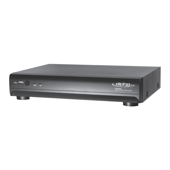
VT-H Series
4, 8, and 16 Channel Digital Video
Recorder with H.264 Compression
• 4, 8 or 16 Video Inputs
• Selectable BNC or VGA Output
• H.264 Compression
• DHCP Support
• Free DDNS Service
• Real-time Display
• 120 PPS Recording
• Remote Viewing over the Internet or LAN
• Supports one internal SATA Hard Drive
• 250GB to 1TB Internal Storage Options
• Quadplex operation
• 4 Alarm Inputs / 1 Relay Out
• Control via IR Remote or Optional USB Mouse
• Backup via Ethernet or USB
Advertisement
Table of Contents

Related Manuals for Vitek VT-H Series


Summary of Contents for Vitek VT-H Series
- Page 1 VT-H Series 4, 8, and 16 Channel Digital Video Recorder with H.264 Compression • 4, 8 or 16 Video Inputs • Selectable BNC or VGA Output • H.264 Compression • DHCP Support • Free DDNS Service • Real-time Display • 120 PPS Recording •...
-
Page 2: Safety Precautions
VT-H Series About this user guide Before installing and using this unit, please read this user guide carefully. Be sure to keep it handy for later reference. The specifications and information are subject to change without notice for quality improvement. - Page 3 VT-H Series These safety precautions must be followed. WARNING Do not use if the unit emits smoke, strange sounds are heard, or odor is emitted. Make sure the power cable is not damaged. Make sure there is no dust accumulation on the power plug or the outlet.
- Page 4 VT-H Series Precautions for supplied AC Adaptor CAUTION Never disassemble or modify. Never get the adaptor wet. CAUTION Use only the supplied AC adapter. Do not connect to other appliances. Do not connect this unit with the AC adapter in areas reachable to children or where pets move freely.
-
Page 5: Table Of Contents
VT-H Series Table of Contents 1. NAME & FUNCTION ............................ 10 1-1. Front panel ............................... 10 1-2. Remote control ............................10 1-3. Rear panel and connection ........................11 2. PREPARATION ............................14 2-1. Selecting the type of monitor (TV monitor and VGA monitor) ............14 2-2. - Page 6 VT-H Series 2-9-2-3. ADSL (PPPoE) ........................... 33 2-9-3. Saving Setup ............................34 2-10. Setup - CONFIG Mode ........................... 34 3. SAVING SETUP ............................36 4. LIVE, SEARCH, AND PLAYBACK ......................36 4-1. Live Viewing Screen ..........................36 4-2. SEARCH Screen ............................38 4-2-1.
- Page 7 VT-H Series 7-1. PC requirements ............................47 7-2. Installing the network viewer ......................... 47 7-3. Live monitoring mode and functions....................48 7-4. Remote search mode and functions ..................... 51 7-5. PC System configuration ........................54 8. NETWORK – BY A WEB-BROWSER VIEWER ..................57 APPENDIX: HOW TO CONNECT TO NETWORK ..................
-
Page 8: Main Features
VT-H Series Main features H.264 Video compression TRIPLEX operation enabling simultaneous recording, playback and networking Instant and convenient data backup & firmware upgrade using USB flash drive Simple user interface Individual channel setting and operation ... -
Page 9: Requirements For Installation And Safety
VT-H Series System components and Installation Requirements for installation and safety This kit should be installed on a flat table or in a rack. The DVR‟s installation location is very important for proper operation of the system. When the DVR is installed too close or the location is poorly ventilated, the DVR may not operate properly and maintenance of the DVR may be difficult. - Page 10 VT-H Series Components of DVR Package The package contains the main unit and its components as specified below. When you purchase the package, please check to ensure the components specified below are included. H Series DVR VT-H-REMOTE Battery1.5V (AAA x 2EA)
-
Page 11: Name & Function
VT-H Series Basic function of the Mouse (Optional) ① Left button: SELECT function ② Right button: ESC function ① Double click: Go to sub menu 1. NAME & FUNCTION 1-1. Front panel Figure 1.1 Front panel Table 1.1. Front LED and Port... -
Page 12: Rear Panel And Connection
VT-H Series ④ F/REW: During playback - To move the playback position 60 seconds backward. During pause - To move the playback position 1 frame backward. ⑤ F/ADV: During playback - To move the playback position 60 seconds forward. During pause - To move the playback position 1 frame forward. - Page 13 VT-H Series Cross type cable LAN Connection – Using a switching hub Connect to the system, using a hub (Switching hub) and an Ethernet cable (10BASE- T/100BASE-TX CAT 5 LAN cable) IP Router or HUB Internet (ADSL) Connection ...
- Page 14 VT-H Series SENSOR INPUT: Connect two signal lines of sensor (infrared ray sensor, heat perception sensor, magnetic sensor) to the desired sensor number. NOTICE SENSOR inputs need dried contact only. Do not input any electric signal. ---: Not operational N/O: Normally open type sensor. When magnetic sensor is closed, sensor sends a signal.
-
Page 15: Preparation
VT-H Series 2. PREPARATION 2-1. Selecting the type of monitor (TV monitor and VGA monitor) 2-1-1. CVBS: Select CVBS to connect general TV monitor 2-1-2. VGA: Select VGA to connect computer VGA monitor The general TV monitor terminal and the computer VGA monitor terminal can not be used simultaneously. - Page 16 VT-H Series button on the remote control. Next, select a user type. User can select one user type (ADMIN, USER1, ◀ ▲ ▶ ▼ USER2, USER3) using the control button ( ) on the remote control and press the SEL button.
- Page 17 VT-H Series SCHEDULE DEVICE – ALARM OUT – – CHANNEL MOTION ZONE MOTION SENSITIVITY – KEY TONE – REMOTE CONTROL ID – SENSOR TYPE STORAGE – OVERWRITE – DISK FORMAT – DISK INFO – RECORDING LIMIT – RECORDING LIMIT DAYS ...
-
Page 18: Setup - Display Mode
VT-H Series CONFIG – SAVE SETUP TO A USB – LOAD SETUP FROM A USB – LOAD DEFAULT – LOAD FACTORY DEFAULT 2-3. Setup – Display Mode Press the SETUP button and enter the password. The setup menu is displayed as pictured below. Select DISPLAY icon and press SEL button to enter the setup menu item. -
Page 19: Setup - Recording Mode
VT-H Series NAME Press SEL button to set the channel name and select OK using the control ◀ ▲ ▶ ▼ button ( COVERT Enable/disable display of the video channel in live display mode. BRIGHTNESS Change the brightness value of the specified channel. (0-100) CONTRAST Change the contrast value of the specified channel. - Page 20 VT-H Series Table 2.4.1. Menu items in Recording mode setup Menu item Description Set the resolution to either 704x480, 704x240, or 352x240 for RESOLUTION NTSC. (For PAL: 704*576/ 704*288/ 352*288) CHANNEL Select a channel to apply the following settings using the control button ◀...
-
Page 21: Recording Schedules
VT-H Series ◀ ▲ ▶ ▼ control button ( PRE RECORD Enable/disable pre-event recording. Pre-event recording time is 3 seconds and only intra-frames are recorded for pre-event recording. Set the post event recording time duration for the specified channel. (10-... -
Page 22: Setup - Device Mode
VT-H Series 2-5. Setup – Device Mode Press the SETUP button and enter the password. The setup menu is displayed as shown below. Select DEVICE icon and press SEL button to enter the setup menu item. Navigate through the menu items and change the value of the menu item using the control button (◀... -
Page 23: Alarm-Out
VT-H Series 2-5-1. ALARM-OUT Figure 2.5.2. ALARM-OUT setup screen Table 2.5.2. Menu item in ALARM-OUT Setup screen Item Description ALARM OUT Select an alarm out number. Available NO: 4CH(1), 9CH(1), 16CH(1) SENSOR IN Enable setting up to 4 cameras of 4/9/16 cameras for each alarm. -
Page 24: Setup - Storage Mode
VT-H Series Figure 2.5.3. Motion Zone selection screen 2-6. Setup – Storage Mode Press the SETUP button and enter the password. The setup menu is displayed as shown below. Select the STORAGE icon and press SEL button to enter the setup menu item. Navigate through the menu items and ◀... -
Page 25: Setup - System Mode
VT-H Series need in the future before you format the hard drive. DISK INFO Hard drive information You will have an option REC ON or REC OFF for the recording VIDEO BACKUP OPTION during the video backup. If set it to REC OFF, the backup speed will be faster. - Page 26 VT-H Series SPACE / Caps Lock (Select either Capital or Lower case) BS (Back space: Erase previous character) / Clear (Erase all characters) DESCRIPTION Press SEL button to view system information. (Hardware version, Software version, Storage size, IP address and MAC address.)
- Page 27 VT-H Series DAY LIGHT SAVING ◀ ▲ ▶ ▼ Select DAYLIGHT SAVING using the control button ( ◀ ▲ Select the appropriate daylight saving time zone using the control button ( ▶ ▼ If choosing EU or OTHERS, set the applicable conditions.
- Page 28 VT-H Series Enable/Disable only key frame transmission. “ON” mode is favorable for use of BANDWIDTH low network bandwidth. Mostly, set “OFF” for normal use. SAVING SEND EMAIL Enable/disable the send e-mail function.(ON/OFF) TRANSMISSION MODE: Enable “sending image” option of the channel that triggered the alarm when an alarm event was triggered.
-
Page 29: Setup - Security Mode
VT-H Series PRIMARY SNTP SERVER: Input the address of the primary NTP time server. SECONDARY SNTP SERVER: Input the address of the secondary NTP time server. TIME ZONE: Greenwich Mean Time (GMT) is a term originally referring to solar time at the Royal Observatory in Greenwich, London. -
Page 30: Setup - Network Mode
VT-H Series Table 2.8.1. Menu Items in PASSWORD Setup Screen Item Description USER AUTHENTICATION PASSWORD CHECK: Select either O or X for the functions such as Setup, Playback (PB), Record OFF (R/OFF) and Network (NET). O: Asks for a password when the given function is selected for all users. - Page 31 VT-H Series Figure 2.9.1. NETWORK setup screen Table 2.9.1. Menu items in Network Setup screen Item Description PORT Port number (Default: 5445) WEB PORT Web Sever Port number NETWORK TYPE Select a type of network connection. Options are: LAN, DHCP, ADSL Note: Other parts of the network setup screen change depending on what network type you select.
-
Page 32: Ports
VT-H Series 2-9-1. Ports When you connect one or more DVRs to a network through an IP sharing device, each device must have a unique TCP port number for access to each unit from outside the LAN. Also, the IP sharing device must be configured for port forwarding so when each port is accessed on the IP sharing device, it will forward to the appropriate DVR. -
Page 33: Network Types
VT-H Series 2-9-2. Network Types 2-9-2-1. LAN 1. For the use of fixed IP. (See your network administrator if you do not have this information.) 2. When the DVR is installed in IP sharer, which is connected with ADSL, a user can assign fixed IP to the DVR from the IP sharer itself using “DMZ”... -
Page 34: Dhcp
VT-H Series 2-9-2-2. DHCP An IP address is automatically assigned by the DHCP server, which automatically assigns an IP address and other parameters to new devices. ADSL or other networks being used, adopt variable IP methods, not fixed IP. This option is used as a way to automatically get an IP address. -
Page 35: Saving Setup
VT-H Series 2-9-3. Saving Setup After changing the network configuration, a confirmation window will appear. To preserve the setup values that you have selected, select YES. Then the system will reboot. Figure 2.9.6. Network setup screen – SAVE SETUP 2-10. Setup - CONFIG Mode Press the SETUP button and enter the password. - Page 36 VT-H Series LOAD SETUP User can upload the configuration of DVR to another DVR using the USB Memory stick. Put the USB stick on the front panel and press SEL to start the loading FROM A USB process. LOAD Select ON to reset the system to the default settings.
-
Page 37: Saving Setup
VT-H Series LOAD Select ON to reset the system to the factory default settings. FACTORY DEFAULT 3. Saving Setup To preserve the setup values that you have changed, select YES. Figure 3.1.1. SAVE SETUP screen 4. Live, Search, and Playback 4-1. - Page 38 VT-H Series Figure 4.1.1. Live Viewing Screen Table 4.1.1. Status Indicator Icons in Live Viewing Screen Icon Description Click MENU on the screen using the mouse to see menu items. Select menu item (SETUP, SEARCH, BACKUP, RECORD, PTZ, SEQUENCE, AUDIO or ALARM- OUT) using the mouse to enable/disable its functions.
-
Page 39: Search Screen
VT-H Series Alarm indicator. When there is an alarm (sensor or motion alarm) in the video channel, this icon will be highlighted bright red. Indicates that a network client is connected to the DVR. Indicates that sequencing mode is enabled. -
Page 40: Time-Line Search
VT-H Series TIME, GO TO SPECIFIC TIME, LOG, and ARCHIVE. How to search for data on the timeline using the mouse or remote controller ① 1 hour moving: 1-hour time bar (Mouse) / F/REW and F/ADV button (remote controller) ②... -
Page 41: Event Search
VT-H Series ◀ ▲ ▶ ▼ 5. Once you select the channel, use the control button ( ) to move to the point you wish to start playing the video clip. 6. Once you have selected the time zone, press the SEL button to playback the recorded video. -
Page 42: Go To First Time
VT-H Series 9. Once the desired event has been selected, press SEL to start playing back the selected video. 10. Press the BACKUP button to launch the archiving function in playback mode. 11. Press the ESC to return to the SEARCH window. -
Page 43: Archive Search
VT-H Series Figure 4.2.6. Log Search Screen 4-2-7. Archive Search The ARCHIVE Search window is used to find previously stored video or images. ◀ ▲ ▶ 1. Select the date to begin searching and navigate through the days using the control button ( ▼... -
Page 44: Play Mode
VT-H Series 4-3. Play mode During playback of a recorded event, the mode changes from SEARCH to PLAY. While in PLAY mode, you may return to the SEARCH screen by pressing the ESC button. Figure 4.3.1. PLAY Mode Screen 5. Back up 5-1. -
Page 45: Video Backup Onto Usb Flash Memory
VT-H Series Figure 5.1.1. Still Image Archiving NOTICE For a backup using a USB stick, a format of the USB stick has to be set to FAT32. 5-2. Video backup onto USB flash memory Video can be captured and archived onto the USB stick or hard drive while playing back recorded video. -
Page 46: Transferring Still Images Or Video From The Archive List
VT-H Series The DVR will convert the corresponding portion of the video into an AVI file. 5-3. Transferring still images or video from the ARCHIVE list The stored data on the hard drive will be found in the ARCHIVE list in SEARCH window. -
Page 47: Upgrading Firmware
VT-H Series 6. Upgrading Firmware In order to upgrade, the firmware upgrade file must first be downloaded and copied into the USB memory stick. Create a new folder in the USB memory stick and name it “upgrade”. Copy the firmware upgrade file “apph_xxxxxx.bin”... -
Page 48: Network Access Using The Exclusive Network Viewer
VT-H Series Figure 6.1.1. Engineering mode screen 7. Network access using the Exclusive network viewer The DVR provides a live remote monitoring feature. Remote monitoring requires installation of the network viewer on your PC. NOTICE In a high bandwidth network, a maximum of four users can access one DVR simultaneously. In a low bandwidth network it is recommended that only one user access the DVR at a time. -
Page 49: Live Monitoring Mode And Functions
VT-H Series After the installation is completed, “UMS Client” icon is displayed on the desktop. 7-3. Live monitoring mode and functions. Button Function Description DATE & TIME Displays the current date and time. Connect/disconnect network connection. CONNECT/DISCONNECT SEARCH Switches the live mode to search mode. - Page 50 VT-H Series PAN/TILT/ZOOM/ FOCUS Control PAN/TILT/ZOOM/FOCUS features on the remote camera. CAPTURE Capture a still image from live screen. Play/pause live video. PLAY/PAUSE The ON/OFF button of the alarm output of ALARM the DVR. When an alarm of the DVR is output, this button becomes Red.
- Page 51 VT-H Series Full screen display - Click the maximize button to display only the screen and hide the operation panel. Image capture of live screen Still-images from a live screen can be captured and saved as BMP or JPEG file.
-
Page 52: Remote Search Mode And Functions
VT-H Series 7-4. Remote search mode and functions Button Function Description Displays the recording time of the data selected DATE & TIME on the time bar at the bottom of the main user interface. DISCONNECT Disconnect network connection. LIVE Switches the search mode to live mode. - Page 53 VT-H Series SEARCH The calendar shows dates with recorded video in CALENDAR a light blue and the selected date in dark blue. TIMELINE BAR The timeline shows recorded data in dark blue on the bar. PLAYBACK The playback buttons. BUTTON DISPLAY MODE Select a channel and screen display mode.
- Page 54 VT-H Series Backup of video in the remote DVR Video recorded in the remote DVR can be backed up on the PC HDD as AVI format. 1. Connect the network to the remote DVR and play the video recorded. 2. Drag the slide on the time scale and drop to the start time for video backup and press the MARK IN button.
-
Page 55: Pc System Configuration
VT-H Series 7-5. PC System configuration Click the SETUP button. Then the Setup dialog is displayed. Setting General Set the Security Option, Save Path, and Miscellaneous. Security Option: Set a password for security options. When you access any of the selected functions, you will need to enter the password. - Page 56 VT-H Series Setting Event Set the record path and the size of local disk space for the log files. LOG – Select to save event log into „log file‟. ICON – Select to display the event on live video.
- Page 57 VT-H Series Setting Record Set the recording conditions and select channels to record. Select the local disk to use and the amount of disk space you want to allow the program to use for recording.
-
Page 58: Network - By A Web-Browser Viewer
VT-H Series 8. Network – By a web-browser viewer The DVR provides a live remote monitoring feature by web-browser viewer. 1. Check the IP address of the DVR from SETUP>SYSTEM>DESCRIPTION>IP ADDRESS. 2. Input the IP address or Domain name address that you pre-registered on www.ddnscenter.com on the address field and press “Go”. - Page 59 VT-H Series 5. Web Browser Viewer is displayed as below. 6. Click CONNECT button in the upper left-hand corner of web-viewer. Then “Connect” dialog is displayed. Enter IP address Domain name address that pre-registered www.ddnscenter.com), Port number and Password and click “Connect.”...
-
Page 60: Appendix: How To Connect To Network
VT-H Series Password: Input Password (The number sets on SETUP>SYSTEM>NETWORK PASSWORD) 7. Then the cameras connected to the DVR are displayed on the screen. APPENDIX: How to connect to network A. How to set the IP address of the DVR and open TCP port of the router The port forwarding is dependent on the brand and model of the router. - Page 61 VT-H Series But if IP is something else like 192.168.x.xxx., you should change IP address, Subnet, Gateway on the DVR. Go to SETUP>NETWORK>LAN on the DVR and change the IP settings to be IP: 192.168.XXX.XXX and Gateway: 192.168.XXX.XXX. (Refer to the user‟s manual of Router.) Open your web browser.
- Page 62 VT-H Series Enter each field Application: Enter a description of the DVR (Example: store1) Start: Enter the first number of the port you need to port forward (Example: 5445) iii. End: Enter the last number of the port you need to port forward (Example: 5445) Protocol: Select Both.
-
Page 63: How To Access Dvr From Remote Pc
VT-H Series You can learn how to port forward many kinds of Routers from the bellow site. http://www.portforward.com/english/routers/port_forwarding/routerindex.htm B. How to access DVR from Remote PC? LAN Connection – Using a switching hub Connect to the system, using a hub (Switching hub) and an Ethernet cable (10BASE-T/100BASE-TX CAT 5 LAN cable) Run the pre-install network client software on the supplied CD. - Page 64 VT-H Series Internet (ADSL) Connection using DDNS Connect to the system, using a Router or ADSL modem and an Ethernet cable (10BASE-T/100BASE-TX CAT 5 LAN cable) Go to SETUP>NETWORK. Set NETWORK TYPE as DHCP and DDNS SERVER as ON. And make sure that DDNS SERVER NAME is bestddns.com...
- Page 65 VT-H Series Serial Number: Input the Serial No. (EX. 43000700XXX) without a space. Domain Name: Input Domain Name for your DVR system Click the DUPLICATION CHECK button to see if the domain name is available. If you see the screen “You can use the Domain name you entered” then click RETURN and click REGISTER button to complete the registration.
- Page 66 VT-H Series 10. Select the site that you will access and click OK.
-
Page 67: Specifications
VT-H Series SPECIFICATIONS 16CH 4CH, 8CH, 16CH, Input Channel, Input Level Composite Composite Composite Signal Format NTSC/PAL Video Video Loss Check Output Main Monitor Output 1 CH BNC, 1CH VGA: Selectable Signal Format NTSC/PAL & VGA Audio Input & Output... - Page 68 VT-H Series 16CH Interface Type Serial ATA I Capacity of 1 Storage Internal HDD Number File system NaFS USB Flash drive Video & Still Image Backup Network Video & Still Image Menu Display Graphic UI User I/F Input Method Remote control, Mouse (Option)
- Page 71 VITEK warrants to the purchaser that products manufactured by VITEK are free of any rightful claim of infringement or the like, and when used in the manner intended, will be free of defects in materials and workmanship for a period of three (3) years, or as otherwise stated above, from the date of purchase by the end user.
- Page 72 28492 CONSTELLATION ROAD VALENCIA, CA 91355 WWW.VITEKCCTV.COM | 888-VITEK-70...
Need help?
Do you have a question about the VT-H Series and is the answer not in the manual?
Questions and answers