Table of Contents
Advertisement
Quick Links
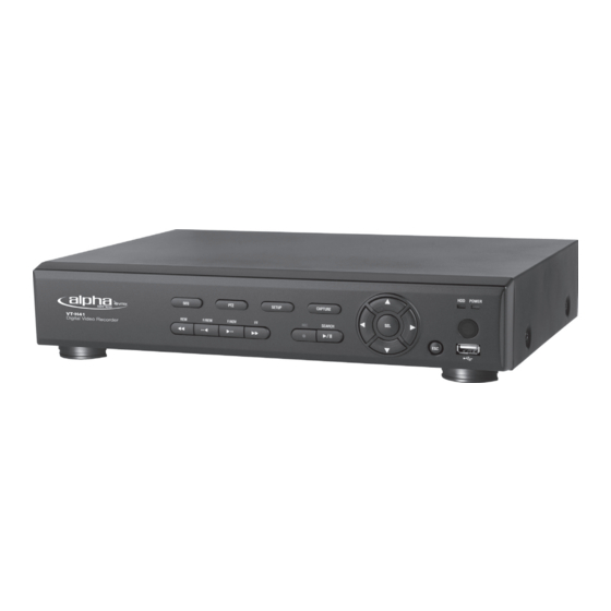
VT-H41
4 Channel Digital Video Recorder
with H.264 Compression
• 4 Video Inputs with 1 BNC & 1 VGA Outputs
• H.264 Compression
• Supports both Dynamic and Static IP Addresses
• Up to 120 IPS Recording / Live Display
• Remote Viewing over the Internet or LAN
• Supports one internal SATA Hard Drive
• 250GB to 1TB Internal Storage Options
• Quadplex operation enabling simultaneous recording,
playback, networking, and backup
• 4 Alarm Inputs / 1 Relay Out
• 4 Audio Inputs & 1 Output
• PTZ Control over RS-485
• Control locally via Included IR Remote control, or Front Panel
Controls
• Backup via Ethernet or USB
Advertisement
Table of Contents

Subscribe to Our Youtube Channel
Related Manuals for Vitek VT-H41


Summary of Contents for Vitek VT-H41
- Page 1 VT-H41 4 Channel Digital Video Recorder with H.264 Compression • 4 Video Inputs with 1 BNC & 1 VGA Outputs • H.264 Compression • Supports both Dynamic and Static IP Addresses • Up to 120 IPS Recording / Live Display •...
-
Page 2: Safety Precautions
VT-H41 SAFETY PRECAUTIONS EXPLANATION OF SYMBOLS This symbol is intended to alert the user to the presence of important operation and maintenance (servicing) instructions in the literature accompanying the appliance. This symbol is intended to alert the user to the presence of unprotected “dangerous voltage”... - Page 3 VT-H41 Do not place a container holding water or other liquids above the unit when it is connected to power. Do not allow the unit to get wet. Do not use during thunder/thunder storms unless used with an uninterruptable power supply (UPS).
-
Page 4: Main Features
VT-H41 Main features H.264 Video compression QUADPLEX operation enabling simultaneous recording, playback, networking, and backup. Instant and convenient data backup & firmware upgrade using USB flash drive Simple User Interface Individual channel setting and operation Motion detection record Free Dynamic DNS... - Page 5 The use of an Automatic Voltage Regulator (AVR) is highly recommended to ensure that stable power is supplied. CAUTION The HDD that is installed in DVR can be replaced or upgraded by and authorized VITEK Repair Center. Warranty will be void if unit is opened by unauthorized personnel.
- Page 6 VT-H41 Components The package contains the main unit and its components as specified below. When you purchase the package, please check to ensure the components specified below are included. Remote Controller Battery1.5V (AAA x 2EA) Adaptor and Power cable Client Software CD...
-
Page 7: Specifications
VT-H41 SPECIFICATIONS ITEM VT-H41 (4CH) VT-H81 (8CH) VT-H161 (16CH) Video Input Channel, Input Level 4CH, Composite 8CH, Composite 16CH, Composite Signal Format NTSC/PAL Video Loss Check 1 CH BNC, 1CH VGA: Selectable Output Main Monitor Output Signal Format NTSC/PAL & VGA Audio Input &... - Page 8 VT-H41 Termination Network Dynamic DNS Yes (Free DDNS) Network Interface 10/100 base-TX Ethernet (RJ-45) Network Client Software (1:1) Live, Search, Backup, PTZF Camera Control Access Web viewer (1:1) Live, Search, Backup, PTZF Camera Control Multi-sites Monitoring System (1:n) Live, Search, Backup, PTZF Camera Control...
-
Page 9: Table Of Contents
VT-H41 INDEX 1. NAME & FUNCTION....................10 1-1. Front panel.............................10 1-2. Remote controller ..........................11 1-3. Rear panel and connection ........................12 2. SETTING UP THE DVR ..................... 15 2-1. Monitor Selection (TV monitor and VGA monitor) ................15 2-2. Live screen ............................16 2-3. - Page 10 VT-H41 7-2. Installing the network viewer ......................55 7-3. Live monitoring mode and functions....................56 7-4. Bi directional audio..........................58 7-5. Remote search mode and functions ....................59 7-6. PC System configuration ........................62 8. NETWORK – BY A WEB-BROWSER VIEWER ............66 APPENDIX: HOW TO CONNECT TO A NETWORK........... 68 A.
-
Page 11: Name & Function
VT-H41 1. NAME & FUNCTION 1-1. Front panel SEQ: To start auto sequencing of the screen in full screen mode. (Toggle) PTZ: To control PTZ operation SETUP: To launch SETUP menu. CAPTURE: To start operations of backup in live or playback mode. -
Page 12: Remote Controller
VT-H41 1-2. Remote controller ID: When a remote control ID number is set in DVR, press it before number. REC: To start and stop manual recording. Number: To select channel (1, 2, 3, & 4) or to enter DVR ID number. -
Page 13: Rear Panel And Connection
VT-H41 1-3. Rear panel and connection 1-3-1. Basic connections Do not power this system on before all the connections are completed. Make sure all the connections are made properly. Faulty connection may result in the system being damaged. The DC plug of the AC adaptor is easy to be unplugged. Please make sure that the plug is... - Page 14 VT-H41 Table 1.2 Rear Panel Connections Four connectors for video input. Connect camera cable to Video-in (NTSC/PAL) VIDEO IN Composite video output in NTSC or PAL format. Connect to Composite Monitor. VIDEO OUT Connector for VGA monitor For engineering use only RS-232 Connector for sensor device.
- Page 15 VT-H41 Internet (ADSL) Connection Connect to the system, using a Router or ADSL modem and an Ethernet cable (10BASE-T/100BASE-TX CAT 5 LAN cable) 1-3-3. Sensor and alarm connections SENSOR INPUT: Connect two signal lines of sensor (infrared ray sensor, heat perception sensor, magnetic sensor) to the desired sensor number.
-
Page 16: Setting Up The Dvr
VT-H41 ---: Not operational N/O: Normally open type sensor. When magnetic sensor is closed, sensor sends a signal. N/C: Normally closed type sensor. When magnetic sensor is opened, sensor sends a signal. ALARM OUTPUT: Use Maximum current: 0.5A/125VAC, Maximum voltage: 1A/30VDC. When controlling lamp and AC operated equipment, control it using separate outside relay. -
Page 17: Live Screen
VT-H41 2-1-2. VGA: Select VGA to connect computer VGA monitor The general TV monitor terminal and the computer VGA monitor terminal can not be used 2-2. Live screen While the system is booting, “INITIALIZING” message is displayed. After the system booting is finished, the video inputs from the cameras are displayed. -
Page 18: Time Setting
VT-H41 Indicator Description Continuous recording in progress Manual recording in progress Sensor alarm recording in progress Motion alarm recording in progress Indicates that audio/audios is/are mute, single, or mixed. Indicates that alarm is detected Indicates that motion is detected Indicates that a network client is connected to the DVR. - Page 19 VT-H41 3. Go to DATE FORMAT field using button and select the date format using button. YYYY/MM/DD (Ex. YYYY-MM-DD (Ex. 2008-05-06) 2008/5/6) MM-DD-YYYY MM/DD/YYYY DD-MM-YYYY 4. Go to DATE & TIME field using button and press the SEL button. 5. Select the date and time that is to be changed using button, change a value using button, and press the SEL button.
-
Page 20: Dls (Day Light Saving) Time Setting
VT-H41 deleted. Selecting “GO TO TEST MODE”: Selects only the video data between “SYSTEM TIME” and “HDD LAST TIME” and will not be deleted. Otherwise, do not select “GO TO TEST MODE”. 2-4. DLS (Day Light Saving) time setting EU Territory – When your time zone belongs to EU territory 1. - Page 21 VT-H41 2. Select BEGIN field using button and press the SEL button. Then DAYLIGHT SAVING BEGIN screen is displayed. 3. Select the date and time that is changed using button, change a value using button, and press the SEL button.
-
Page 22: Operation - Record
VT-H41 3. OPERATION - RECORD The system has 6 recoding modes. CONTINUOUS recording – Recording continuously when the DVR is turned on. C icon is displayed on the screen. (Refer to page 25) MOTION DETECTION recording – Recording when the DVR detects motion form input video. -
Page 23: Motion Detection Recording
VT-H41 Repeat this step to set the other channel as necessary. Press ESC button to go to SAVE SETUP and save the 3-2. MOTION DETECTION recording A motion detection setting is available for each channel. Set the basic record menu using the direction buttons before setting Motion detection. - Page 24 VT-H41 When FULL ZONE is selected, the DVR detects motion from the entire video screen. Set only MOTION SENSITIVITY. Select the grids for motion detection using button and SEL button. Then the selected grids are displayed in Pink color. Go to MOTION SENSITIVITY using button and select the sensitivity using button.
-
Page 25: Sensor Recording
VT-H41 Go to POST RECORD using button and select the time as necessary using button. The available POST RECORD time: 5 to 60 seconds. Repeat this step to set the other channel as necessary. Press ESC button to go to SAVE SETUP and save the setting 3-3. - Page 26 VT-H41 Go to RECORDING BY field using button and select SENSOR using button. Go to DEVICE>CHANNEL>SENSOR RECORDING using button and select the number of sensors that are linked with the video channel using button. Go to PRE RECORD using button and select ON or OFF as necessary using button.
-
Page 27: Manual Recording
VT-H41 Go to ALARM/BEEP DURATION using button and select alarm/beep duration as necessary using Enter button. Press ESC button to go to SAVE SETUP and save the setting. 3-4. Manual recording To start manual recording, press REC button. Then, “R” is displayed on the screen and the DVR starts recording all channels. - Page 28 VT-H41 MOTION ZONE MOTION SENSITIVITY SENSOR TYPE PRE RECORD POST EVENT RECORD Go to RECORDING BY field using button and select SCHEDULE using button. Go to SCHEDULE using button and press SEL button. Then SCHEDULE setting screen is displayed. (When the channel 1 is selected from CHANNEL field, “SCHEDULE – CH1” is displayed.)
- Page 29 VT-H41 : MOTION DETECTION recording mode setting applies to the whole day. : SENSOR recording mode setting applies to a specified time of every day. EXAMPLE of copying the CH1 SCHEDULE recording setting to CH2 Set the CH1 SCHEDULE and return RECORD menu using ESC button.
-
Page 30: Operation - Playback
VT-H41 press SEL button. Then the CH1 SCHEDULE recording setting is copied to CH2. 4. OPERATION - PLAYBACK The system has 7 methods of searching a recorded video. EVENT SEARCH – Searching through the calendar, channel, and recording mode. (Refer to page 33) TIMELINE SEARCH –... - Page 31 VT-H41 Go to EVENT SEARCH and press SEL button. Then SEARCH screen is displayed. Select the date, a channel, and the type of recording mode using buttons and SEL button. A: Showing all the recorded data list of every type of recording mode M: Showing the recorded data list by motion detection.
-
Page 32: Timeline Search
VT-H41 4-2. TIMELINE SEARCH Press SEARCH button. Then SEARCH menu is displayed. Go to TIMELINE SEARCH and press SEL button. Then SEARCH calendar screen is displayed. Select the date using buttons and SEL button. Then Timeline screen is displayed. Move the vertical Yellow line to the time between 0 to 24 HOUR using buttons and SEL button. -
Page 33: Go To Specific Time
VT-H41 4-3. GO TO SPECIFIC TIME Press SEARCH button. Then SEARCH menu is displayed. Go to GO TO SPECIFIC TIME and press SEL button. Then SEARCH screen is displayed. Select the date and time using buttons and press SEL button. -
Page 34: System Log
VT-H41 4-6. SYSTEM LOG Press SEARCH button. Then SEARCH menu is displayed. Go to SYSTEM LOG and press SEL button. Then SYSTEM LOG calendar screen is displayed. Select the date using buttons and press SEL button. To change pages of the log data list, use buttons. -
Page 35: Operation - Backup To Usb Flash Drive
VT-H41 Select the date using buttons and press SEL button. Then ARCHIVE LIST screen is displayed. Select one of the archived data listed using buttons and press SEL button. To change pages of the archived data list, use buttons. Then, the archived still-image or the first frame of video data is displayed. -
Page 36: Archiving And Backup Jpeg In Live Mode
VT-H41 Archiving and backup JPEG in Live mode – JPEG image can be archived on HDD and be backed up to USB flash drive in live mode. (Refer to page 39) Archiving and backup VIDEO in Playback mode – JPEG, AVI, or EXCLUSIVE VIDEO can be archived on HDD and be backed up to USB flash drive in playback mode. -
Page 37: Archiving And Backup Video In Playback Mode
VT-H41 Then SAVING screen with backup status bar is displayed after “CHECKING USB” message. After the backup is done, “BACKUP IS COMPLETED” message is displayed. When the DVR can not recognize USB thumb drive or no USB thumb drive is connected to the USB terminal, “PLEASE CHECK BACKUP DEVICE”... - Page 38 VT-H41 Press CAPTURE button at the scene of video to be backed up. Then SELECT BACKUP FILE Select a file type from JPEG, AVI, or EXCLUSIVE VIDEO using TYPE screen is displayed. buttons and press SEL button. Then DURATION screen is displayed.
-
Page 39: Backup Jpeg, Avi, Or Exclusive Video From Archive Search
VT-H41 After the backup is done, “BACKUP IS COMPLETED” message is displayed. 5-3. Backup JPEG, AVI, or EXCLUSIVE VIDEO from ARCHIVE search Press SEARCH button. Then SEARCH screen is displayed. Go to ARCHIVE field using buttons and press SEL button. - Page 40 VT-H41 Select VIDEO clip from the list using buttons and SEL button. Then a paused image or the first scene of the video is displayed. Press CAPTURE button. Select AVI or EXCLUSIVE VIDEO using buttons and press SEL button. Select USB FLASH DRIVE using buttons and press SEL button.
-
Page 41: Playback Of Avi Or Exclusive Video
VT-H41 After the backup is done, “BACKUP IS COMPLETED” message is displayed. 5-4. Playback of AVI or EXCLUSIVE VIDEO Playback of AVI format: AVI format video can be played back by Windows Media Player™ or other media player that is compatible with AVI format video. -
Page 42: Setup
VT-H41 6. SETUP Press the SETUP button, then the password window is displayed. The default password is 1111, which can be entered by pressing the up button 4 times and then pressing the SEL button. After input password, the SETUP screen is displayed. - Page 43 VT-H41 mode. Dwell time for each cannel display in sequential display mode. SEQ-DWELL TIME Set the visibility level of the On Screen Display (OSD) OSD CONTRAST Select the channel for applying the following settings. CHANNEL Enable/disable display of the video channel in live display mode DISPLAY Enable/disable the specified channel to be included in sequential list.
-
Page 44: Record
VT-H41 ON: The channel is included in sequencing channels. OFF: The channel is NOT included in sequence list. BRIGHTNESS – Set the brightness of the channel using buttons. Setting values of the display bar: 0% ~ 100% (The most brightness) CONTRAST –... - Page 45 VT-H41 RESOLUTION – Select the resolution for the recording using buttons. 352x240: The input video is recorded as 352x240 resolution. 704x240: The input video is recorded as 704x240 resolution. 704x480: The input video is recorded as 704x480 resolution. The resolution setting is applied to every channel.
-
Page 46: Device
VT-H41 6-3. DEVICE Item Description Select the channel for applying the following settings. CHANNEL Select Full Zone or Partial Zone for motion sensing. MOTION ZONE Set the motion sensitivity for the specified channel. MOTION SENSITIVITY Select the channel to link with sensor. - Page 47 VT-H41 ALARM - Select an event to link with alarm using buttons. OFF: An event signal is NOT linked with the external alarm. SENSOR: A sensor event signal is linked with the external alarm. MOTION: An event signal of motion is linked with the external alarm.
-
Page 48: Network
VT-H41 RIGHT button for FOCUS near or far of the selected camera. FOCUS Initialize the PTZ settings of the selected camera. INITIALIZE REMOTE CONTROLLER ID (Example: Number 3) Select REMOTE CONTROLLER ID using buttons and select the ID number from 3 using buttons. - Page 49 VT-H41 Input a port number using buttons and press SEL button. When you connect one or more DVRs to a network through an IP sharing device, each device must have a unique TCP port number for access to each unit from outside the LAN.
- Page 50 VT-H41 Input the registered PASSWORD that is necessary for ADSL connection using buttons and press SEL button. Press ESC button. Then the APPLY NETWORK ADDRESS screen is displayed. Select CONFIRM using buttons and press SEL button. Then the DVR reboots automatically.
- Page 51 VT-H41 1. Regarding the use of fixed IP, please ask your network administrator if you do not have this information. 2. When DVR is installed in IP sharer that is connected with ADSL, a user can assign fixed IP to DVR from IP sharer itself using “DMZ” function out of such Setting of DDNS –...
-
Page 52: Storage
VT-H41 6-5. STORAGE Item Description Enable/Disable Overwrite existing old video data when hard disk OVERWRITE drive is full Format hard disk drive HDD FORMAT Shows the HDD information DISK INFORMATION Set the limit days for recording to the hard disk drive from 1 to... -
Page 53: System
VT-H41 6-6. SYSTEM Press SEL to see system information. DESCRIPTION Select the preferred date and time display. DATE FORMAT Set the present date and time. If DLS function is ON, user can SET DATE & TIME not enter into this menu and change data and time. - Page 54 VT-H41 NETWORK PASSWORD – Select NETWORK PASSWORD using buttons and press SEL button. Then the NETWORK PASSWORD screen is displayed. Changing of PASSWORD (ADMIN/NETWORK) Select ADMIN PASSWORD / NETWORK PASSWORD using buttons and press SEL button. Then the Current password input screen is displayed.
- Page 55 After uploading is completed, then the DVR reboots automatically. USB UPGRADE Download the firmware of the DVR from the VITEK web-site www.vitekcctv.com Create a new folder (This folder name should be “upgrade”) in the USB thumb drive and paste the firmware “app-xxx.bin”...
-
Page 56: Network Access Using The Exclusive Network Viewer
VT-H41 7. Network access using the Exclusive network viewer The DVR provides a live remote monitoring feature. Remote monitoring requires installation of the network viewer on your PC. NOTICE high bandwidth network, maximum four users access simultaneously. In a low bandwidth network it is recommended that only one user access the DVR at a time. -
Page 57: Live Monitoring Mode And Functions
VT-H41 After the installation is completed, “UMS Client” icon is displayed on the desktop. 7-3. Live monitoring mode and functions. Button Function Description Displays the current date and time. DATE & TIME Connect/disconnect network CONNECT/DISCONNECT connection.. - Page 58 VT-H41 Switches live mode search SEARCH mode. Select a channel and screen display DISPLAY MODE mode. Control PAN/TILT/ZOOM/FOCUS PAN/TILT/ZOOM/ features on the remote camera. FOCUS Capture a still image from live screen. CAPTURE Play/pause live video. PLAY/PAUSE ON/OFF button alarm ALARM output of the DVR.
-
Page 59: Bi Directional Audio
VT-H41 Full screen display - Click the maximize button to display only video and hide the operation panel. Image capture of live screen Still-image of live screen can be captured and saved as BMP or JPEG file. 1. Click the channel to be captured. Then the channel screen is surrounded with a red line. -
Page 60: Remote Search Mode And Functions
VT-H41 7-5. Remote search mode and functions Button Function Description Displays the recording time of the data DATE & TIME selected on the time bar at the bottom of the main user interface. Disconnect network connection. DISCONNECT Switches the search mode to live mode. - Page 61 VT-H41 The calendar shows dates with recorded SEARCH video in light blue and the selected date CALENDAR in dark blue. The timeline shows recorded data in dark TIMELINE BAR blue on the bar. The playback buttons. PLAYBACK BUTTON Select a channel and screen display mode.
- Page 62 VT-H41 Backup of video on the remote DVR Video recorded on the remote DVR can be backed up on the PC HDD as AVI format. 1. Connect the network to the remote DVR and play the video recorded in the remote DVR.
-
Page 63: Pc System Configuration
VT-H41 7-6. PC System configuration Click the SETUP button. Then the Setup dialog is displayed. Setting General Set security options, save path, and Automatic reconnection. Security Option: Set a password for security options. When you access any of the selected functions, you will need to enter the password. - Page 64 VT-H41 Display network statistics: If a user selects this function, the client S/W will display network status, Bit rate and Frame rate. Time Format: Change the time format mode on the Client software display. Setting Site The remote DVRs can be added, modified, and removed.
- Page 65 VT-H41 Setting Record Set the recording conditions and select channels to record. Select the local disk to use and the amount of disk space you want to allow the program to use for recording.
- Page 66 VT-H41 Setting Video Set the video screen. Setting Language Select the language of the network client viewer.
-
Page 67: Network - By A Web-Browser Viewer
VT-H41 8. Network – By a web-browser viewer The DVR provides a live remote monitoring feature by web-browser viewer. 1. Check the IP address of the DVR from SETUP>SYSTEM>DESCRIPTION>IP ADDRESS. 2. Input address Domain name address that pre-registered www.vitekddns1.com on the address field and press “Go”. - Page 68 VT-H41 www.vitekddns1.com), Port number and Password and click “Connect” Server address: Input IP address of the DVR from SETUP>SYSTEM>DESCRIPTION>IP ADDRESS or Domain name address that you pre-registered on www.vitekddns1.com Port: Input Port number (The number sets on SETUP>NETWORK>PORT) Password: Input...
-
Page 69: Appendix: How To Connect To A Network
VT-H41 APPENDIX: How to connect to a network A. How to set the IP address of the DVR and open the TCP port of the router? Connect network cable between DVR and Router or ADSL modem. Default network setting on DVR are... - Page 70 VT-H41 Open your web browser. Enter the router IP address in the address bar (The router IP address are different with the brand and model.), click GO. admin is Port Range Forwarding Enter each field. Application: Enter a description of the DVR (Example: store1) Start: Enter the first number of the port you need to port forward (Example: 5445) iii.
-
Page 71: How To Access Dvr From Remote Pc
VT-H41 B. How to access DVR from Remote PC? LAN Connection – Using a switching hub Connect to the system, using a hub (Switching hub) and an Ethernet cable (10BASE- T/100BASE-TX CAT 5 LAN cable) IP Router or HUB Run the pre-install the network client software on the supplied CD. (Refer to Chapter 6. - Page 72 VT-H41 Connect to the system, using an Router or ADSL modem and an Ethernet cable (10BASE- T/100BASE-TX CAT 5 LAN cable) Go to SETUP>NETWORK. Set NETWORK TYPE as DHCP and DDNS SERVER as ON. And make sure that DDNS SERVER NAME is vitekddns1.com Go to Setup menu of Router and open TCP port 5445 using Port Forwarding.
- Page 73 VT-H41 Site Name: Input the name of the DVR. IP Address: Input the Domain Name that is registered on http://www.vitekddns1.com (EX. XXXXX.vitekddns1.com) Port Number: Input the port number. Protocol: Select TCP. Password: Input the network password. Click CONNECT button. Then the Connect window is displayed.
- Page 74 VT-H41...
- Page 75 VT-H41...
- Page 76 28492 CONSTELLATION ROAD VALENCIA, CA 91355 WWW.VITEKCCTV.COM | 888-VITEK-70...
Need help?
Do you have a question about the VT-H41 and is the answer not in the manual?
Questions and answers