
Related Manuals for Beam SD7 series


Summary of Contents for Beam SD7 series
- Page 1 Suitable for the Iridium Extreme 2012 Designed and manufactured by BEAM Communications Pty Ltd Portable Satellite Telephone...
-
Page 2: User Information
8 Anzed Court, Mulgrave, Victoria, 3170, AUSTRALIA Information furnished by BEAM Communications Pty Ltd is believed to be accurate and reliable. However, no responsibility is assumed by BEAM for its use, or for any infringement of patents or other rights of third parties, which may result from its use. -
Page 3: Beam Communications
BEAM Communications BEAM Communications, a wholly owned subsidiary of World Reach Limited (WRR), listed on the Australian Stock Exchange, is a world leader in design, manufacture and distribution of specialized communications equipment for the Iridium Satellite Network. BEAM’s commitment to be at the forefront has continued to increase its share of the global satellite communications market. -
Page 4: Table Of Contents
Contents BEAM Communications Conventions in this Manual Terminology Package Contents Safety Information About this equipment Installation Guidelines DriveDOCK Extreme Usage Data Communications Assuring Quality of Iridium Service Specification Summary Trouble Shooting BEAM Warranty Conditions... -
Page 5: Conventions In This Manual
Conventions in this Manual Warnings, cautions and notes appear throughout this manual and are represented by following conventions. WARNING / CAUTION: This symbol and associated text indicate a warning note providing information to prevent damage to equipment or personal injury. NOTE / IMPORTANT / TIP: This symbol and associated text indicate a note providing general operating information. -
Page 6: Terminology
The ® symbol, mark and logos are owned by the respective companies of which the symbol follows. Any use of such marks by BEAM Communications is under license. Other trademarks and trade names are those of their respective owners. Radio Frequencies... -
Page 7: Package Contents
Package Contents Check that your DriveDOCK Extreme package contains: 1 x DriveDOCK Extreme Docking Cradle ‡ 1 x Microphone ‡ 1 x Speaker ‡ 1 x DC Power Cable / Fuse Kit ‡ 1 x RAM Bracket ‡ 3 x M4 Screws and washers ‡... -
Page 8: Additional Information
Additional Information For the latest in supporting software and documentation for DriveDOCK Extreme please visit: www.beamcommunications.com/support Data To use data on the DriveDOCK Extreme, the specific BEAM USB driver must be downloaded from the above link and installed on the PC connected to the DriveDOCK. -
Page 9: Safety Information
Safety Information IMPORTANT! Please read the following information carefully before installing and using the BEAM DriveDOCK Extreme. Failing to follow instructions may compromise the safety of the product and may result in personal injury and/or equipment damage. Please consult your supplier if you have any further questions. WARNING: DO NOT open equipment. - Page 10 WARNING: POTENTIALLY EXPLOSIVE ATMOSPHERES • Turn your phone OFF and DO NOT remove your battery or remove the Extreme handset from the cradle when you are in any area with a potentially explosive atmosphere. • Obey all signs and instructions. •...
- Page 11 ◊ National Radiological Protection Board of the United Kingdom, GS 11, 1988 ◊ American National Standards Institute (ANSI) IEEE. C95. 1-1992 These standards are based on extensive scientific review by scientists, engineers, and physicians from universities, government health agencies, and industry groups. They review the available body of research to develop ANSI standard.
-
Page 12: Electronic Devices
Electronic Devices Most modern electronic equipment is shielded from RF signals. Certain equipment may not be shielded against the RF signals from your phone. Pacemakers The Health Industry Manufacturers Association recommends that a mini- mum separation of 16cm (six inches 6”) be maintained between a wireless phone’s antenna and a pacemaker to avoid potential interference with the pacemaker. -
Page 13: Posted Facilities
can, under certain unique conditions, be subject to interference by mobile radio operation. Although the transceiver exceeds all requirements regarding RF emissions, you should mount the transceiver as far as possible from the guidance system and/or braking modulator box (usually located in the trunk) to minimize any interference. -
Page 14: About This Equipment
About this equipment DriveDOCK Extreme Key Features DriveDOCK Extreme CRADLE • Securely holds Extreme handset • Robust design and construction • Charges Extreme handset battery ready for use • Integrated antenna connection; Iridium and GPS • Integrated USB connectivity HANDSFREE MODE •... - Page 15 INSTALLATION • Supports 9 - 32V DC power input • Installation via universal mount, also suitable for wall mounting • Antenna, mic and speaker installed in a convenient location QUALITY • 2 year replacement guarantee for peace of mind • 100% factory tested •...
- Page 16 Tracking / Alert Monitoring The DriveDOCK Extreme utilizes the Iridium Extreme’s tracking and emergency notification functions. The Track button is enabled (factory default setting). The Alert Loop (wires to an emergency distress button) is disabled, and requires Eagle Configuration Tool to enable it. Tracking When the Track button is pressed it initiates a Quick GPS message in the Iridium Extreme handset.
-
Page 17: Equipment Overview
Equipment Overview Latch button Latch PRESS Feature buttons Mini-USB port Intelligent handset port Privacy handset Status LED Iridium connector GPS connector Horn alert (BLUE) Alert loop IN (BROWN) Alert loop OUT DriveDOCK Extreme (GREEN) Input Power (4-way microfit) Speaker connector Mic Connector... -
Page 18: Installation Guidelines
Installation Guidelines This guide outlines the process for installing the BEAM DriveDOCK Extreme in conjunction with an Iridium Extreme portable handset. This kit must only be used with the Iridium Extreme handset. • Only qualified personnel should install communication equipment. If necessary, contact the vehicle manufacturer for air bag information specific to the vehicle. -
Page 19: Guidelines For Electrical Connections
• In a vehicle equipped with electronically controlled anti-skid brakes, route all cables on the opposite side of the vehicle from the braking modulator box to minimize possible interference from the phone. • Keep all in-line connectors accessible. • The suggested path for routing cables in vehicles without wiring troughs is alongside the drive shaft tunnel, under the carpet. -
Page 20: Installation Procedure
WARNING: Do not connect the DriveDOCK Extreme interface power cable to power the unit until the full installation is completed. Installation Procedure Installing the DriveDOCK Extreme Cradle Install the components in the following order. More detailed instructions can be found in the sections following. Mount the DriveDOCK Extreme cradle a) Install the external Iridium Antenna Connection and/or b) Install the GPS Antenna Connection (optional) - Page 21 Step 1 - Mounting the DriveDOCK Extreme cradle The DriveDOCK Extreme is supplied with a universal RAM® mount bracket that enables mounting to any flat surface (vertical or horizontal) within a vehicle, attached on a wall or on a table as required. Attach one pivot base to the rear of the DriveDOCK Extreme using the M4 screws and washers supplied.
- Page 22 Step 2a - Install the external Iridium Antenna Connection The external antenna connection can be found at the rear of the dock on the cable loom. Install the Iridium antenna in an appropriate location that has a clear sky view. Connect the RF cable between the antenna and the TNC female connector at the rear of the DriveDOCK Extreme.
- Page 23 Step 2b - Install the GPS Antenna Connection (optional) The GPS connection is NOT optional if the tracking or Emergency function is required. Or, the GPS connection is optional if the tracking or Emergency function is NOT required. If connected, and tracking is enabled, position or location information will be shown on your tracking messages and alert messages.
- Page 24 Step 3 - Connect the speaker and microphone The DriveDOCK cradle comes with an external speaker and microphone for hands-free operation. Mount the speaker in the appropriate location and ensure the lead is sufficient to reach the cradle. Mount the microphone about 30cm away from where you normally speak and ensure the lead is long enough to reach the cradle.
- Page 25 Step 5 - Connect Privacy Handset (Optional–Extra Order) The DriveDOCK Extreme provides a 4-pole 3.5mm audio socket at the bottom of the Dock, for connection to the BEAM Privacy Handset. This provides a local handset function, conveniently mounted next to the DriveDOCK Extreme cradle.
- Page 26 Step 6 - Connect the Intelligent Handset (Optional - Extra Order) The Intelligent handset provides the user with a dial pad and LCD display and allows the user to make calls or send/receive SMS without having access to the Extreme handset. The Intelligent handset is enabled when it is removed from the cup.
- Page 27 (+) Vin 9 to 32VDC To Battery Positive Terminal (3A Fuse recommended) BLACK (-) OV Power Ground To Negative Terminal or chassis YELLOW (IGN) Ignition / Accessory To ACC switched power (1A Fuse recommended) Connect the YELLOW wire to the vehicle accessory power. If the accessory power is unavailable, this may be connected to a vehicle ignition voltage.
- Page 28 Step 8 - Horn Output / Audio System Mute The DriveDOCK provides a BLUE wire output on the rear cable loom for either controlling an external ringer such as a vehicle horn, or to Mute the vehicle Audio System during a call. The operation of this mode is selected in Eagle, and the default is Horn mode.
- Page 29 Step 9 - Bluetooth® Configuration (Optional) DriveDOCK has an in-built Bluetooth® module for voice connectivity. NOTE: In this manual, when there is a reference to the Bluetooth® button or the Bluetooth® LED it is referring to the button shown below located on the front of the DriveDOCK Extreme.
- Page 30 Step 10 - Tracking & Alert Configuration (optional) Tracking & Alert requires the installation of a GPS antenna, and setup of the tracking and/or alerting messages. Please refer to the Eagle software to enable and configure Tracking & Alert. Please refer to the Iridium Extreme Handset User Manual to configure the tracking and emergency alert operation and destinations.
-
Page 31: Drivedock Extreme Usage
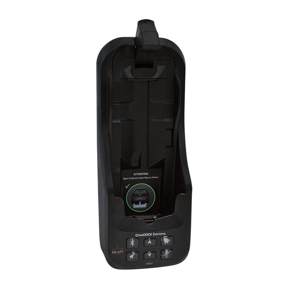
DriveDOCK Extreme Usage Extended Iridium Extreme Battery Iridium provide an optional extra high capacity battery that can replace the standard battery. To accommodate the larger battery, a Battery Infill must be removed from the Dock. Removal Place a fingernail/coin/ screwdriver in the slot and push the infill towards the centre of Dock. - Page 32 Docking your Extreme handset At the base of the Iridium Extreme handset there is an accessory connector cover. Open the cover and move it to the back of the handset, securing it to the two rear retaining features. Press down the latch button and then gently rotate it up to open the latch, then place the Iridium Extreme handset into the DriveDOCK Extreme Lift the latch back over the handset or until it Click’s into place...
- Page 33 Removing the Iridium Extreme To remove the handset, first press down on the latch button and then rotate the latch up and away from the handset. The handset can now be slid up and out of the DriveDOCK. Refit the accessory connector cover to maintain the IP rating of the Iridium Extreme handset.
- Page 34 Check Before Use To ensure the best operation of the phone and Dock, upgrade to the latest firmware revisions in both products Upgrade Firmware Ensure that the DriveDOCK Extreme is running with the latest firmware which can be located at: www.beamcommunications.com/support/iridium Ensure that the Iridium Extreme Handset is running with the required compatible firmware which can be located at:...
- Page 35 NOTE: The Extreme handset can be removed whilst powered, however the handset will turn off automatically. If it is removed during a call, the Extreme Handset will attempt to remain in call as long as antenna is extended and in sky view. The call may drop out during this transition, and the phone may turn off.
- Page 36 Charging the Iridium Extreme Handset The DriveDOCK Extreme provides charging power to the Extreme handset via its accessory connector. The Extreme Handset battery is a lithium-ion cell which has a safety temperature range whilst charging. This range is from 0°C - 45°C (32°F - 104°F). Due to the increased heating effects on the Extreme handset whilst it is docked and being charged, it is ideal for the ambient temperature to be approximately 10°C below the 45°C upper limit for the handset to charge the...
-
Page 37: Placing Voice Calls
Placing Voice Calls Hands-Free Phone Call – Mobile Originating Dial the number (using the full country codes) on the Extreme handset keypad whilst docked, or the Intelligent handset keypad (if connected). Press the GREEN key (or OK on Intelligent handset) to start the connection. Beeps should be heard from the speaker to indicate a call is in progress. - Page 38 NOTE: The DriveDOCK Extreme internal ringer will also sound during an incoming call. This can be changed by a single press of the Ringer button, whilst out of call. (Please refer to the section “Ringer Selection” for more details.) Bluetooth® Phone Call - Mobile Originating A Bluetooth®...
-
Page 39: Privacy Handset Use
To end the call by either one of the bellow: • Pressing the Bluetooth® headset answer button • Pressing the red key on the Extreme keypad. Once the call is in progress, Option A from “A Bluetooth® Phone Call – Mobile Originating”... -
Page 40: Intelligent Handset Use
Intelligent Handset Use Intelligent Handset Phone Call - Mobile Originating Remove the Intelligent handset from its cup. Dial the phone number (using the full country code) on the keypad. Press the OK GREEN key. A beep sound should be heard from the handset to indicate a call is in progress and the following message will be displayed on the Extreme handset. -
Page 41: Mute Mode
Mute Mode NOTE: The Mute function only operates DURING a call. Once the call is ended, Mute mode is exited. In this manual, when there is a reference to the Mute button or the Mute LED it is referring to the button shown below located on the front of the DriveDOCK Extreme Mute functionality The mute function of the DriveDOCK Extreme allows the user to mute... - Page 42 Tracking & Alert Operations NOTE: In this manual, when there is a reference to the Track button or the Track LED it is referring to the button shown below located on the front of the DriveDOCK Extreme Enable Tracking & Alert The Tracking button is enabled by default.
- Page 43 Activate Alert Mode Alert mode can be activated by one of the following two methods: Pressing the SOS button on the top of the Iridium Extreme handset. If the alert loop is broken (OPEN) . This feature must be enabled in the Eagle application.
-
Page 44: Sleep Mode
Sleep mode The DriveDOCK can enter a low-power SLEEP mode after pre-defined waiting time (20 minutes by default) when a Extreme Handset is docked AND its accessory input is turned OFF (and is not set to be “ignored” in the Eagle application). - Page 45 DriveDOCK Extreme Front Panel LOCATION BUTTON MODE ACTION LED/SOUND Mute press In a Call: On/off Mute the microphone LED turns RED (uplink) on the Hands- Muted free, optional privacy handset, or optional LED turns OFF Intelligent Handset Not muted In a Call: Up/Down Increase/decrease Audio will sound...
- Page 46 LOCATION BUTTON MODE ACTION LED/SOUND Not in Call: Ringer Single Press Cycle through the ring Ring tone playback tones and the output and the output device (internal buzzer device changes. and external speaker). The LED FLASHING last Ringer type sounded (Fast) BLUE when is then saved.
- Page 47 LOCATION BUTTON MODE ACTION LED/SOUND In Tracking Mode*: Single Press (until 1 beep Send a tracking message LED flashes GREEN sounds) to the pre-configured for 5 seconds. destination in the Extreme A beep will sound Handset to indicate that a tracking message is to be sent# Single Press...
- Page 48 Button LED Reference GREEN BLUE ORANGE Mic / Uplink ILLUMINATED audio Mute GREEN BLUE ORANGE Privacy Handset or Incoming call FLASHING (slow) Intelligent ringing Handset in use. Ring Tone FLASHING (fast) Playback BLUE ORANGE Connected with a paired BT device. ILLUMINATED Ready for accepting incoming call or switch to an active call...
- Page 49 All Buttons Firmware Upgrade Mode ILLUMINATED Status LED GREEN YELLOW - DTR present on Ready to receive - No Iridium signal data port ILLUMINATED or place a call - Not registered - LED brightness (registered) - No SIM card adjustment mode - Data Call in progress (DCD Voice Call in...
-
Page 50: Data Communications
Data Communications The DriveDOCK Extreme provides the convenience of accessing Iridium data services via the mini-USB connector located on the bottom of the cradle while the Extreme handset is docked. You should consult your service provider for full details on the availability of this service with your account. - Page 51 To connect a PC/laptop to the DriveDOCK Extreme bottom mini-USB port, you will require a mini-USB-B to USB-A data cable. This cable is included in your original Extreme package. USB Driver Installation The DriveDOCK Extreme USB data port requires an interface driver to be installed on the user’s computer prior to undertaking data communication.
- Page 52 AT Commands When utilizing the USB data communication port, the DriveDOCK Extreme cannot activate AT commands that could interrupt the docking station’s synchronization with the Extreme handset. Therefore, the DriveDOCK Extreme will block or limit AT commands that could cause any adverse effects to the functional operation of the cradle.
- Page 53 Iridium Extreme Display Definitions Display Status indicators and Icons The following icons will appear in your Extreme handset display to provide you with various information about the phone’s activity. Main Screen Components Battery Strength Indicates an SMS message has been received Indicates a voicemail has been received Indicates the keypad is locked...
- Page 54 Power-On Messages Once your phone is powered on, you may see: MESSAGE MESSAGE DESCRIPTION Bad Card See Supplier. Your SIM car has been damaged or incorrectly issued. Contact your service provider for information. Check Card The SIM card is damaged or inserted the wrong way. Denied Your phone has seen a network, but has been denied access.
-
Page 55: Assuring Quality Of Iridium Service
Assuring Quality of Iridium Service Iridium is committed to providing subscribers around the world with con- sistent, reliable, quality voice and data access all day, every day. The Iridium satellite system is monitored for call performance from numerous locations 24 hours a day, 7 days a week in order to achieve this. There are conditions that can compromise the quality of the service you may receive. - Page 56 Cabling Using an externally mounted antenna provides an ideal solution for many applications. It is very important that both the antenna cabling and antenna are BEAM approved products. Always ensure all RF connectors are screwed together firmly and ensure there are no sharp bends in the cabling between the DriveDOCK Extreme and the antenna.
-
Page 57: Specification Summary
Specification Summary Electrical & Environmental Specifications POWER SPECIFICATIONS Rated Input 9-32V DC, 2A max Average Power Current Power Consumption @ 12V Watts Standby 70mA 0.84W Transmit + Charging 0.7A 8.4W Sleep Mode 60mW INTERFACES One horizontal 2-pin Microfit connector on the cable External Speaker and loom for speaker and one vertical 2-pin Microfit Microphone... - Page 58 Antenna Integrated chip antenna Bluetooth® identifier: B03005. CE 89/336/EEC - #EC/2006/20013C. FCC part 15 class B: DriveDOCK contains Regulatory Transmitter Module FCC ID: QOQWT11. Canada: Cert# 5123A-BGTWT11E Japan:07215089/AA/00 The Bluetooth® word, mark and logos are owned by the Bluetooth® SIG, Inc. and any use of such marks by BEAM Legal Communications is under license.
- Page 59 Cradle Dimensions DriveDOCK Extreme Dimensions in millimeters 75.9...
- Page 60 DriveDOCK Extreme Dimensions in millimeters with optional Privacy Handset attached 167.6 77.9...
-
Page 61: Trouble Shooting
Trouble Shooting This chapter provides information to help you troubleshoot problems you may encounter while running the DriveDOCK. Q1 The Extreme handset is docked into the DriveDOCK, but the Extreme handset is not turned on and the DriveDOCK doesn’t seem to have power. Press the Ring button and you should hear a tone. - Page 62 The Extreme handset is inserted into the DriveDOCK. The battery indicator on the Extreme handset does not show that the battery is being charged. There are a number of reasons which could stop the Extreme battery charging. When the Extreme handset is inserted into the DriveDOCK, please wait for about 100 seconds for the charging to start.
-
Page 63: Beam Warranty Conditions
This warranty policy may be expanded or limited, for particular categories of products or Customers, by information sheets published as deemed appropriate by BEAM Communications. The warranty for third party Products is that of the third party and not BEAM warranty. - Page 64 BEAM COMMUNICATIONS GLOBAL HEAD OFFICE +61 3 8588 4500 +61 3 9560 9055 AMERICAS +1 954 376 5062 EUROPE +44 208 144 1405 +44 208 289 3542 Sales sales@beamcommunications.com General info@beamcommunications.com Support support@beamcommunications.com www.beamcommunications.com AFRICA ASIA AUSTRALIA EUROPE MIDDLE EAST...
Need help?
Do you have a question about the SD7 series and is the answer not in the manual?
Questions and answers