Table of Contents
Advertisement
Quick Links
Download this manual
See also:
User Manual
APC-3X17B
Panel PC User Manual
Release Date
_
Revision
Apr. 2012
V1.0
®2012 Aplex Technology, Inc.
All Rights Reserved.
Published in Taiwan
Aplex Technology, Inc.
15F-1, No.186, Jian Yi Road, Zhonghe District, New Taipei City 235, Taiwan
Tel: 886-2-82262881 Fax: 886-2-82262883 E-mail:
aplex@aplex.com.tw
URL:
www.aplex.com.tw
APC-3X17B User Manual
1
Advertisement
Table of Contents

Related Manuals for Aplex APC-3X17B


Summary of Contents for Aplex APC-3X17B
- Page 1 Panel PC User Manual Release Date Revision Apr. 2012 V1.0 ®2012 Aplex Technology, Inc. All Rights Reserved. Published in Taiwan Aplex Technology, Inc. 15F-1, No.186, Jian Yi Road, Zhonghe District, New Taipei City 235, Taiwan Tel: 886-2-82262881 Fax: 886-2-82262883 E-mail: aplex@aplex.com.tw...
-
Page 2: Warning
Disclaimer This information in this document is subject to change without notice. In no event shall Aplex Technology Inc. be liable for damages of any kind, whether incidental or consequential, arising from either the use or misuse of information in this document or in any related materials. -
Page 3: Packing List
Always disconnect power when the system is not in use. ◆ Disconnect power when you change any hardware devices. For instance, when you connect a jumper or install any cards, a surge of power may damage the electronic components or the whole system. APC-3X17B User Manual... -
Page 4: Table Of Contents
3.9 Exit Options..................58 Chapter 4 Installation of Drivers 4.1 Intel Chipset Driver.…………………………...…………………………61 4.2 Intel Graphics Media Accelerator Driver...……………………………..64 4.3 Intel 82574L LAN Device Driver………………………………………….68 4.4 Realtek ALC662 HD Audio Driver Installation…….………….…………71 4.5 Microsoft .NET Framework 3.5 Service Installation……………………73 APC-3X17B User Manual... - Page 5 Figure 1.5: Rear View………………………………………………………..13 Figure 1.6: Panel mounting…………………………………………………..14 Figure 1.7: VESA mounting…………………………………………………..14 Figure 2.1: Mainboard Dimensions…………………………………..……..15 Figure 2.2: Jumpers and Connectors Location_ Board Top………………...16 Figure 2.3: Jumpers and Connectors Location_ Board Bottom…………..17 Figure 5.1 Birdeye’s View of Control Board…………………………………76 APC-3X17B User Manual...
-
Page 6: Specifications
Dimensions (WxHxD) 410 x 310 x 87.8 mm 439 x 348 x 93.3 mm 484 x 400 x 94.3 mm Operating Temperature -10~50℃ -20~60℃ Storage Temperature 10%~90%@ 40℃, non-condensing Relative Humidity Certificate CE / FCC Class A APC-3X17B User Manual... -
Page 7: Dimensions
1.2 Dimensions Figure 1.1: Dimensions of the APC-3517B APC-3X17B User Manual... -
Page 8: Figure 1.2: Apc-3717B Dimensions
Figure 1.2: Dimensions of the APC-3717B APC-3X17B User Manual... -
Page 9: Figure 1.3: Apc-3917B Dimensions
Figure 1.3: Dimensions of the APC-3917B APC-3X17B User Manual... -
Page 10: Installation Of Hdd
Get the HDD screwed to the bracket with the four screws as shown by the arrows in the picture. Step 3 Connect the cable to the HDD as shown in the picture, making sure the red stripe of the cable is rightly positioned. APC-3X17B User Manual... - Page 11 Step 4 Get the four screws as circled tightened to secure the HDD. As shown in the picture Step 5 That’s how it should look after it has been installed. APC-3X17B User Manual...
-
Page 12: Installation Of Pci Add-On
Step 3 After sliding the addon into the PCI expansion slot, get the one screw as circled tightened to finish the connection. Step 4 To finish the job, just fasten the 2 screws as shown in the picture. APC-3X17B User Manual... -
Page 13: Brief Description
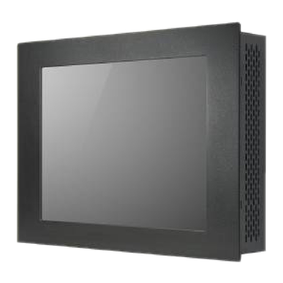
1.5 Brief Description of the APC-3X17B The APC-3517B/3717B/3917B is a high performance, compact and panel-mount industrial PC, which comes with a 15-inch (luminance of 300 cd/m²)/17-inch (luminance of 350 cd/m²)/19-inch (luminance of 300 cd/m²) TFT LCD. It is powered by an Intel Socket P Core 2 Duo Processor, up to Intel P8600 2.4GHz processor. -
Page 14: Panel Mounting
The APC-3517B/3717B/3917B panel PC is designed to be panel-mounted as shown in Figure 1.6. Just carefully place the unit through the hole and tighten the given 10 screws from the rear to secure the mounting. Figure 1.6: Panel mounting of the APC-3517B/3717B/3917B Figure 1.7: VESA mounting of the APC-3517B/3717B/3917B APC-3X17B User Manual... -
Page 15: Chapter 2 Hardware
Chapter 2 Hardware 2.1 Mainboard Figure 2.1: Mainboard Dimensions APC-3X17B User Manual... -
Page 16: Installations
PC104+ port (capable of adjusting IO voltage) richer extension functions. The product is widely used in various sectors of industrial control. 2.2.1 Jumpers Setting and Connectors Figure 2.2: Jumpers and Connectors Location_ Board Top APC-3X17B User Manual... -
Page 17: Figure 2.3: Jumpers And Connectors Location_ Board Bottom
(2.0mm Pitch 1X2 Pin Header),ATX Power and Auto Power on jumper setting. Mode Open ATX Power Close Auto Power on (Default) 2. RTC/SRTC: (2.0mm Pitch 1X2 Pin Header)CMOS clear jumper, CMOS clear operation will permanently reset old BIOS settings to factory defaults. RTC/SRTC CMOS APC-3X17B User Manual... - Page 18 Signal Pin# Name Pin1 VBAT PIN2 Ground 4. DCIN: (5.08mm Pitch 1x3 Pin Connector),DC9V ~ DC32V System power input connector。 Power Pin# Input DC+9V~32 Pin1 Pin2 Ground Pin3 Ground Location Location Location (5.4.6.) Power Mode (5.4.4.) (5.4.5.) APC-3X17B User Manual...
- Page 19 (2.0mm Pitch 1X3 box Pin Header), connect PSON and 5VSB and Ground signal,support ATX Power model. Reserved. Pin# Signal Name Pin1 ATX PSON PIN2 ATX Ground PIN3 ATX 5VSB 7. CPU1: (Socket P), installing the CPU Socket. APC-3X17B User Manual...
- Page 20 (CRT 2.0mm Pitch 2X5 Pin Header), Video Graphic Array Port, Provide 2x5Pin cable to VGA Port, they can not work at the same time for CRT and VGA1. Signal Name Pin# Pin# Signal Name CRT_RED Ground CRT_GREEN Ground CRT_BLUE VGA_EN CRT_H_SYN CRT_DDCDAT APC-3X17B User Manual...
- Page 21 Intel GM45 chipset, the interface features dual channel 18/24-bit output. Signal Name Pin# Pin# Signal Name VDD5 VDD5 Ground Ground VDD33 VDD33 LB_D0_N LA_D0_N LB_D0_P LA_D0_P Ground Ground LB_D1_N LA_D1_N LA_D1_P LA_D1_P Ground Ground LB_D2_N LA_D2_N APC-3X17B User Manual...
- Page 22 (Type DB9),Rear serial port, standard DB9 Male serial port is provided to make a direct connection to serial devices. COM1 port is controlled by pins No.1~6 of JCOM1,select output Signal RI or 5V or 12v, For details, please refer to description of APC-3X17B User Manual...
- Page 23 DSR (Data Set Ready) RTS (Request To Send) CTS (Clear To Send) RI (Ring Indicator) 19. COM5: (2.0mm Pitch 2X5 Pin Header),COM5 Port, standard RS232 ports are provided. They can be used directly via COM cable connection. APC-3X17B User Manual...
- Page 24 JCOM6,select output Signal 5V or 12v, For details, please refer to description of JCOM6. Signal Pin# Pin# Signal Name Name Ground JCOM6 select Setting 22. USB4/USB5/USB6/USB7: (Double stack USB type A), Rear USB connector, it provides up to 4 USB2.0 ports, speed up to 480Mb/s. APC-3X17B User Manual...
- Page 25 Line In is used for the connection of external audio source via a Line in cable. MIC is the port for microphone input audio. Signal Name Pin# Pin# Signal Name FRONT_OUTP-L FRONT_OUTP_ FRONT_OUTN_ FRONT_OUTN_ FRONT_JD LINE1_JD LINE_IN_L LINE1_IN_R MIC2_IN_L MIC2_IN_R Ground MIC2_JD 26. BZ: Onboard buzzer. APC-3X17B User Manual...
- Page 26 (2.0mm Pitch 1X3 Pin Header), Wake up setting jumper. pin 1~2 are used to select signal for COM4 Wake up, pin 2~3 are used to select signal for PCI devices Wake up, JRI Pin# Function Close 1-2 PCI_PME for COM4 Close 2-3 PCI-PME for PCI APC-3X17B User Manual...
- Page 27 33. MIO2: (1.25mm Pitch 2x20 Connector), Front panel connector. Function Signal Name Pin# Pin# Signal Name Function H_LED+ HDD_LED PWR-LED P_LED+ H_LED- Ground Ground P_LED- RESET- Ground MIO_PSON- PSON+ RESET RESET Ground PSON- BUZZER+ BUZZER- BUZZER- BUZZER+ APC-3X17B User Manual...
- Page 28 Pin9-10: BUZZER, They are used to connect an external buzzer. Pin11-18: GPIO IN/GPIO OUT, General-purpose input/output port, it provides a group of self-programming interfaces to customers for flexible use. Pin19-24: PS2 KB/MS, PS/2 keyboard and mouse port, the port can be connected to APC-3X17B User Manual...
- Page 29 35. SATA_P1/SATA_P2: (2.5mm Pitch 1x2 box Pin Header), Two onboard 5V output connectors are reserved to provide power for SATA devices. Pin# Signal Name +DC5V Ground Note: Output current of the connector must not be above 1A. APC-3X17B User Manual...
- Page 30 MPCIE1 SCREW HOLES, H5 for H6 for card (30mmx50.95mm) assemble. 40. LED1: LED STATUS. Green LED for Motherboard Standby Power Good status, Yellow LED for HDD status. 41. TB-522: ASB-M801 I/O Card, via a dedicated cable connected to ASB-M801 MIO1. APC-3X17B User Manual...
- Page 31 PWR LED: status. POWER LED COM3: (Type DB9),I/O serial port, it provides selectable RS422/RS485 serial signal output. RS422 Type (option) RS485 Type (option) Signal Name Pin# Pin# Signal Name 422_RX+ 422_RX- 422_TX- 485- 422_TX+ 485+ Ground Ground APC-3X17B User Manual...
- Page 32 Card socket), it is located at TB-522 and serves as an insert interface for Type I and Type II Compact Flash card. The operating voltage of CF card can be set as 3.3V or 5V. The default setting of the product is 3.3V. APC-3X17B User Manual...
- Page 33 42. TB-520P1: TB-520P1 connect to ASB-M801T/ET PC104+ connector, PC104+ is located at the top, It provides one PCI slot. APC-3X17B User Manual...
-
Page 34: Chapter 3 Bios Setup
Press F11 key to enter Boot Menu during POST, as shown by the following figure. Please select boot device: Network: IBA GE Slot 0200 v1353 Network: IBA GE Slot 0300 v1353 ↑and ↓ to move selection ENTER to select Boot device ESC to boot using defaults APC-3X17B User Manual... -
Page 35: Bios Setup Utility
Select a field Build Date : 05/13/11 Use[+] or [-] to : M801V001 configure system Time. Processor Genuine Intel(R) CPU @ 2.00GHz Speed :2000MHz ← Select Screen ↑↓ Select Item System Memory Charge Field Size :1981MB Tab Select Field APC-3X17B User Manual... -
Page 36: Advanced Settings
► CPU Configuration ► IDE Configuration ► Super IO Configuration ► Hardware Health Configuration ► ACPI Configuration ► AHCI Configuration ► MPS Configuration ► PCI Express Configuration ► Smbios Configuration ← Select Screen ► USB Configuration APC-3X17B User Manual... - Page 37 Execute-Disable Bit Capability [Enabled] +- Charge Field Intel(R) C-SATAE tech [Disabled] F1 General Help F10 Save and Exit ESC Exit V02.61 © Copyright 1985-2006 American Mega trends , Inc. Hardware Prefetcher: [Enabled] [Disabled] Adjacent Cache Line Prefetch: APC-3X17B User Manual...
- Page 38 +- Charge Field ► Third IDE Master : [Not F1 General Help Detected] F10 Save and Exit ► Fourth IDE Master : [Hard ESC Exit Disk] Hard Disk Write Protect [Disabled] IDE Detect Time Out (Sec) [35] APC-3X17B User Manual...
- Page 39 [IDE] [RAID] [AHCI] SATA#2 Configuration: [Enhanced] [Disabled] Hard Disk Write Protect: [Disabled] [Enabled] IDE Detect Time Out : [35] [10] [15] [20] [25] [30] ATA(PI) 80Pin Cable Detection: [Host & Device] [Host] [Device] 3.4.3 Super IO Configuration APC-3X17B User Manual...
- Page 40 COM3 Options: [RS485 ] [RS422] [RS422] for RS422 Mode [RS485] for RS485 Mode 3.4.4 Hardware Health Configuration BIOS SETUP UTILITY Advanced Hardware Health Configuration 55℃/131℉ System Temperature :33℃/91℉ 60℃/140℉ CPU Temperature :30℃/86℉ 65℃/149℉ CPUFAN Speed :4800 RPM APC-3X17B User Manual...
-
Page 41: System Temperature
Show you the current CPU temperature. CPUFAN Speed: Show you the current CPU Fan operating speed. Maximum CPU Temperature: [60℃/140℉] 55℃/131℉ 65℃/149℉ 70℃/158℉ Minimum PWM Duty for CPU Fan: [60%] [50%] [70%] [80%] 3.4.5 ACPI Configuration ACPI Setting: [Advanced ACPI Configuration] APC-3X17B User Manual... - Page 42 High Performance Event Timer: [Disabled] [Enabled] 3.4.6 AHCI Configuration BIOS SETUP UTILITY Advanced Enables For supporting AHCI Setting AHCI BIOS Support [Enabled] AHCI CD/DVD Boot Time out [35] ► AHCI Port0 [Not Detected] ► AHCI Port1 [Not Detected] APC-3X17B User Manual...
-
Page 43: Mps Configuration
+- Charge Field F1 General Help F10 Save and Exit ECS Exit V02.61 © Copyright 1985-2006 American Mega trends , Inc. MPS Revision: [1.1] [1.4] 3.4.8 PCI Express Configuration BIOS SETUP UTILITY Advanced Enables/Disables PCI Express Configuration APC-3X17B User Manual... -
Page 44: Smbios Configuration
Smbios Smi Support [Enabled] Support for PnP Func 50h-54h ← Select Screen ↑↓ Select Item Charge Field General Help F10 Save and Exit ESC Exit V02.61 © Copyright 1985-2006 American Mega trends , Inc. Smbios Smi Support: [Enabled] [Disabled] APC-3X17B User Manual... -
Page 45: Advanced Pci/Pnp Settings
Personal Computer Interconnect, is a computer bus that allows I/O device to operate nearly as fast as CPU in its own way. Some technical terms will be mentioned here. We recommend that non-professional users not make changes from factory default settings. APC-3X17B User Manual... - Page 46 F10 Save and Exit IRQ5 ESC Exit [Available] IRQ7 [Available] IRQ9 [Available] IRQ10 [Available] IRQ11 [Available] V02.61 © Copyright 1985-2006 American Mega trends , Inc. Clear NVRAM: [No] [Yes] Plug & Play OS: [No] [Yes] PCI Latency Timer: [64] APC-3X17B User Manual...
- Page 47 Available: Specified IRQ is available to be used by PCI/PnP devices. Reserved: Specified IRQ is reserved for use by legacy ISA devices. DMA Channel 0/1/3/5/6/7: [Available] [Reserved] Available: Specified DMA is available to be used by PCI/PnP devices. APC-3X17B User Manual...
-
Page 48: Boot Settings
V02.61 © Copyright 1985-2006 American Mega trends , Inc. Boot Setting Configuration: Configure Settings during System Boot. Quick Boot: [Enabled] [Disabled] Allows BIOS to skip certain tests while booting .This will decrease the time needed to boot the system. APC-3X17B User Manual... - Page 49 [Disabled] Interrupt 19 Capture: Enabled: Allows option ROMs to trap interrupt 19. [Disabled] [Enabled] Boot Device Priority: Specifies the Boot Device Priority sequence. Hard Disk Devices : Specifies the Boot Device Priority sequence from available Hard Drives. APC-3X17B User Manual...
-
Page 50: Security Settings
Always: Check password while invoking setup a well as on each boot. Boot Sector Virus Protection: [Disabled] [Enabled] Enabled / Disabled Boot Sector Virus Protection. Type the password with up to 6 characters and then press Enter key. This will APC-3X17B User Manual... -
Page 51: Advanced Chipset Settings
► North Bridge Configuration ► South Bridge Configuration ← Select Screen ↑↓ Select Item Enter Go to sub screen General Help F10 Save and Exit ESC Exit V02.61 © Copyright 1985-2006 American Mega trends , Inc. APC-3X17B User Manual... -
Page 52: North Bridge Configuration
► Video Function Configuration ESC Exit V02.61 © Copyright 1985-2006 American Mega trends , Inc. Memory Remap Feature: [Enabled] [Disabled] Memory Hole: [Disabled] [15MB-16MB] Initate Graphic Adapter: Select which graphics controller to use as the primary boot device. APC-3X17B User Manual... - Page 53 +- Charge option Backlight Control Level [Level 8] F1 General Help Backlight Control Mode [DC] F10 Save and Exit Backlight Image Adaptation ESC Exit [VBIOS-Default] V02.61 © Copyright 1985-2006 American Mega trends , Inc. DVMT Mode Select: APC-3X17B User Manual...
- Page 54 [1366x768 18bit 1ch] [1024x768 24bit 2ch] [1280x1024 24bit 2ch] [1440x900 24bit 2ch] [1600x900 24bit 2ch] [1680x1050 24bit 2ch] [1920x1080 24bit 2ch] Backlight Control Support [VBIOS-Default] [Both BLC & BIA Disabled] [BLC Enabled] Backlight Control Control: [Level8] [Level0] [Level1] [Level2] APC-3X17B User Manual...
- Page 55 Ports] 2 USB Ports USB2.0 Controller [Enabled] 4 USB Ports Keep USB Power at S5 [Enabled] 6 USB Ports 8 USB Ports Wireless Controller [Enabled] 10 USB Ports HAD Controller [Enabled] 12 USB Ports SMBUS Controller [Enabled] APC-3X17B User Manual...
- Page 56 [2 USB Ports] [4 USB Ports] [6 USB Ports] [8 USB Ports] [10 USB Ports] USB 2.0 Controller: [Enabled] Keep USB Power at S5: [Enabled] [Disabled] Wireless Controller [Enabled] [Disabled] HDA Controller: [Enabled] [Disabled] SMBUS Controller: [Enabled] [Disabled] APC-3X17B User Manual...
- Page 57 PCIE Port 0: [Auto] [Enabled] [Disabled] PCIE Port 1: [Auto] [Enabled] [Disabled] PCIE Port 2: [Auto] [Enabled] [Disabled] PCIE Port 3: [Auto] [Enabled] [Disabled] PCIE Port 4: [Auto] [Enabled] [Disabled] PCIE High priority Port: [Disabled] [Port 0] [Port1] APC-3X17B User Manual...
-
Page 58: Exit Options
Load Optimal Defaults Load Failsafe Defaults ← Select Screen ↑↓ Select Item Enter Go to sub screen General Help F10 Save and Exit ESC Exit V02.61 © Copyright 1985-2006 American Mega trends , Inc. Save Changes and Exit: APC-3X17B User Manual... -
Page 59: Discard Changes
F7 key can be used for this operation) [OK] [Cancel] Load Optimal Defaults: Load Optimal Defaults? F9 key can be used for this operation) [OK] [Cancel] Load FailSafe Defaults: Load FailSafe Defaults? F9 key can be used for this operation) [OK] [Cancel] APC-3X17B User Manual... -
Page 60: Chapter 4 Installation Of Drivers
This chapter describes the installation procedures for software and drivers under the windows XP. The software and drivers are included with the motherboard. The contents include Intel chipset driver VGA driver LAN drivers Audio driver .NET framework 3.5 driver Installation instructions are given below. APC-3X17B User Manual... -
Page 61: Intel Chipset Driver
4.1 Intel Chipset Driver To install the Intel chipset driver, please follow the steps below. Step 1: Select Chipset from the list Follow the step-by-step installation process to install the driver. APC-3X17B User Manual... - Page 62 APC-3X17B User Manual...
- Page 63 Click Finish, when the installation process is complete, the Setup Complete screen appears. See as picture. APC-3X17B User Manual...
-
Page 64: Intel Graphics Media Accelerator Driver
4.2 Intel Graphics Media Accelerator driver To install the VGA drivers, follow the steps below to proceed with the installation. 1. Click Intel(R) GM45 Chipset Family Graphics Driver. Follow the step-by-step installation process to install the Graphics Media Accelerator driver. APC-3X17B User Manual... - Page 65 APC-3X17B User Manual...
- Page 66 APC-3X17B User Manual...
- Page 67 Click FINISH; A Driver Installation Complete. APC-3X17B User Manual...
-
Page 68: Intel 82574L Lan Device Driver
4.3 Intel 82574L LAN Device Driver To install the Intel R 82574L Gigabit LAN connect device driver, please follow the steps below. Select LAN from the list Follow the step-by-step installation process to install the LAN driver. APC-3X17B User Manual... - Page 69 APC-3X17B User Manual...
- Page 70 Click FINISH; A Driver Installation Complete. APC-3X17B User Manual...
-
Page 71: Realtek Alc662 Hd Audio Driver Installation
4.4 Realtek ALC662 HD Audio Driver Installation To install the Realtek High Definition (HD) Audio driver, please follow the steps below. Select Audio from the list Follow the step-by-step installation process to install the Realtek HD Audio driver. APC-3X17B User Manual... - Page 72 Click FINISH; A Driver Installation Complete. APC-3X17B User Manual...
-
Page 73: Microsoft .Net Framework 3.5 Service Installation
4.5 Microsoft .NET Framework 3.5 Service Installation To install the Microsoft .NET Framework 3.5 Service, please follow the steps below. APC-3X17B User Manual... - Page 74 APC-3X17B User Manual...
- Page 75 APC-3X17B User Manual...
-
Page 76: Figure 5.1 Birdeye's View Of Control Board
Before installing the Windows 2000/XP driver software, you must have the Windows 2000/XP system installed and running on your computer. You must also have one of the following PenMount 6000 series controller or control boards installed: PM6500, PM6300. APC-3X17B User Manual... -
Page 77: Installing Software
When the system first detects the controller board, a screen appears that shows “Unknown Device”. Do not use this hardware wizard. Press Cancel. 2. Insert the product CD install setup.exe. the screen below would appear. Click touch panel driver APC-3X17B User Manual... - Page 78 3. A License Agreement appears. Click “I accept…” and “Next” APC-3X17B User Manual...
- Page 79 4. Ready to Install the Program. Click “Install” 5. Installing APC-3X17B User Manual...
- Page 80 6. The “Install Shield Wizard Completed” appears. Click “Finish”. APC-3X17B User Manual...
-
Page 81: Software Functions
‘Advanced Calibration’ adjusts aging touch screens. Standard Calibration Click this button and arrows appear pointing to red squares. Use your finger or stylus to touch the red squares in sequence. After the fifth red point calibration is complete. To skip, press ‘ESC’. APC-3X17B User Manual... - Page 82 Dmcctrl.exe - calibration ($) 0= Standard Calibration 4=Advanced Calibration 4 9=Advanced Calibration 9 16=Advanced Calibration 16 25=Advanced Calibration 25 1. Please select a device then click “Configure”. You can also double click the device too. 2.Click “Standard Calibration” to start calibration procedure APC-3X17B User Manual...
- Page 83 NOTE: The older the touch screen, the more Advanced Mode calibration points you need for an accurate calibration. Use a stylus during Advanced Calibration for greater accuracy. Please follow the step as below: 3.Come back to “PenMount Control Panel” and select “Tools” then Click “Advanced Calibration”. APC-3X17B User Manual...
- Page 84 Select “Device” to calibrate, then you can start to do “Advanced Calibration”. NOTE: Recommend to use a stylus during Advanced Calibration for greater accuracy. APC-3X17B User Manual...
- Page 85 Setting APC-3X17B User Manual...
- Page 86 About This panel displays information about the PenMount controller and driver version. APC-3X17B User Manual...
-
Page 87: Multiple Monitors
Enable the multiple display function as follows: 1. Check the “Multiple Monitor Support” box; then click “Map Touch Screens” to assign touch controllers to displays. 2. When the mapping screen message appears, click “OK” APC-3X17B User Manual... - Page 88 3. If you change the resolution of display or screen address, you have to redo Map Touch Screens so the system understands where the displays are. 4. If you more monitor mapping one touch screen, Please press ‘S’ to skip mapping step. APC-3X17B User Manual...
- Page 89 Advanced Calibration Enable Advanced Calibration function Right Button Icon Enable right button function. The icon can show on Desktop or System Tray (menu bar). About You can see how many devices of PenMount controller that are plugged to your system APC-3X17B User Manual...
- Page 90 The PenMount monitor icon (PM) appears in the menu bar of Windows 2000/XP system when you turn on PenMount Monitor in PenMount Utilities. PenMount Monitor has the following function PenMount Rotating Functions The PenMount driver for Windows 2000/XP supports several display rotating software packages. APC-3X17B User Manual...
- Page 91 2. Choose the rotate function (0°, 90°, 180°, 270°) in the 3rd party software. The calibration screen appears automatically. Touch this point and rotation is mapped. NOTE: The Rotate function is disabled if you use Monitor Mapping APC-3X17B User Manual...
Need help?
Do you have a question about the APC-3X17B and is the answer not in the manual?
Questions and answers