Table of Contents
Advertisement
Quick Links
APC-3X19A
th
15", 17", and 19" 4
Gen. Intel Core i7/i5/i3 Panel PC
User Manual
Release Date
Revision
Oct. 2015
V1.0
®2015 Aplex Technology, Inc.
All Rights Reserved.
Published in Taiwan
Aplex Technology, Inc.
15F-1, No.186, Jian Yi Road, Zhonghe District, New Taipei City 235, Taiwan
Tel: 886-2-82262881 Fax: 886-2-82262883 E-mail:
aplex@aplex.com.tw
URL:
www.aplextec.com
APC-3X19A User Manual
0
Advertisement
Table of Contents

Related Manuals for Aplex APC-3X19A


Summary of Contents for Aplex APC-3X19A
- Page 1 Gen. Intel Core i7/i5/i3 Panel PC User Manual Release Date Revision Oct. 2015 V1.0 ®2015 Aplex Technology, Inc. All Rights Reserved. Published in Taiwan Aplex Technology, Inc. 15F-1, No.186, Jian Yi Road, Zhonghe District, New Taipei City 235, Taiwan Tel: 886-2-82262881 Fax: 886-2-82262883 E-mail: aplex@aplex.com.tw...
-
Page 2: Revision History
Revision History Reversion Date Description 2015/10/06 Official Version APC-3X19A User Manual... -
Page 3: Warning!/Caution
There are dangerous high voltages inside. Caution Risk of explosion if the battery is replaced with an incorrect type. Batteries should be recycled where possible. Disposal of used batteries must be in accordance with local environmental regulations. APC-3X19A User Manual... -
Page 4: Packing List/Safety Precautions
Always disconnect power when the system is not in use. ◆ Disconnect power when you change any hardware devices. For instance, when you connect a jumper or install any cards, a surge of power may damage the electronic components or the whole system. APC-3X19A User Manual... -
Page 5: Table Of Contents
Chapter 1 Getting Started 1.1 Features……………….……………………………………...………………………………….6 1.2 Specifications…………………………………………………………………………………...6 1.3 Dimensions…………………………………..………………………...…………………..8 1.4 Brief Description of APC-3X19A..………………………………………………..……11 1.5 Installation of Riser Card………………………………………………………………….12 1.6 Installation of HDD/SSD – 15”………………………………………………………….13 1.7 Installation of HDD/SSD – 17” and 19”..…………………………………………..14 1.8 Mounting of APC-3X19A………………………………………………………………….15 Chapter 2 Motherboard 2.1 Motherboard IMB-181-L Specifications…………….………..………………..…16... - Page 6 Figure 1.1: Dimensions of APC-3519A…………………….…..………………..……...8 Figure 1.2: Dimensions of APC-3719A……………………………………………………..9 Figure 1.3: Dimensions of APC-3919A……………………………………………………10 Figure 1.4: Front View of APC-3X19A…..…….…..………………………………..11 Figure 1.5: Rear View of APC-3X19A…….……………………………………………..11 Figure 1.6: Panel Mounting and Wall Mounting of APC-3x19A………...……14 Figure 2.1: Motherboard Layout…………………………………………..……………….17 APC-3X19A User Manual...
-
Page 7: Getting Started
1 x DC Power 3-pin Terminal Block Connector Power 1 x Rocker Switch for Power on/off 2 x LED Indication for Power and HDD Others 1 x 8-pin Terminal Block 3 in/3 out/VCC/GND (option) 1 x CF Slot (option) APC-3X19A User Manual... -
Page 8: Dimensions
410 x 310 x 122.5mm 439 x 348 x 119.1mm 484 x 400 x 119mm Net Weight 9.5Kg 10.8Kg 12.9Kg Environmental Operating 0~50 °C Temperature Storage Temperature -30~70 °C Storage Humidity 10%~90%@ 40℃, non-condensing Certificate Meet CE / FCC Class A APC-3X19A User Manual... -
Page 9: Figure 1.1: Dimensions Of Apc-3519A
1.3 Dimentions Figure 1.1: Dimensions of APC-3519A APC-3X19A User Manual... -
Page 10: Figure 1.2: Dimensions Of Apc-3719A
Figure 1.2: Dimensions of APC-3719A APC-3X19A User Manual... -
Page 11: Figure 1.3: Dimensions Of Apc-3919A
Figure 1.3: Dimensions of APC-3919A APC-3X19A User Manual... -
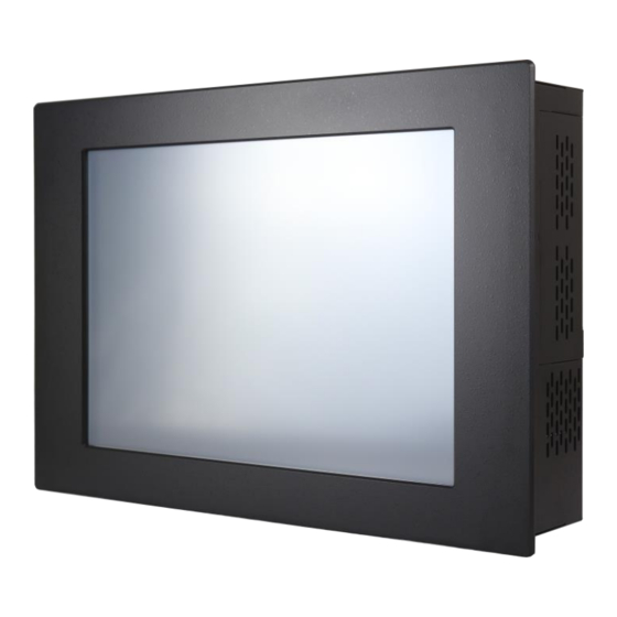
Page 12: Brief Description Of Apc-3X19A
Additionally, 1 x CF slot and 1 x 8-pin terminal block 3 in/3 out/VCC/GND are optional. APC-3X19A is steel black or aluminum with resistive, and it can be aluminum with Projected Capacitive Touch. It can be VESA 75 x 75 mounted for 15” and 17”, and VESA 100 x 100 mounted for 19”. -
Page 13: Installation Of Riser Card
Step 3 Pull out the iron sheet. Step 4 You can replace the riser card on the iron sheet. Then Put it into the chassis. Step 5 This is how it looks after riser card is installed correctly. APC-3X19A User Manual... -
Page 14: Installation Of Hdd/Ssd - 15
HDD/SSD through the same way. Remove the screw by hand. User screwdriver is also acceptable. Step 3 Pull the HDD bracket out carefully. Step 4 You can replace HDD or SSD by unscrewing the four screws as shown in the picture. APC-3X19A User Manual... -
Page 15: Installation Of Hdd/Ssd - 17" And 19
HDD bracket. Both of them can be installed HDD/SSD through the same way. Unscrew the screws Step 3 Pull the bracket out carefully. You can replace HDD or SSD by unscrewing the two screws as shown in the picture. APC-3X19A User Manual... -
Page 16: Mounting Of Apc-3X19A
1.8 Mounting of APC-3X19A The APC-3X19A panel PC is designed to be panel-mounted as shown in Figure 1.6 just carefully place the unit through the hole and tighten the given screws from the rear to secure the mounting. And it also can be wall mounted as shown in the figure. -
Page 17: Chapter 2 Motherboard
Ethernet 10/100/1000 Mbps Ethernet Controller GbE LAN1: Intel® I210, LAN2: Intel® I217LM (with v-Pro support) Connector 2 x RJ-45 Max Data SATA SATA2 (3.0Gb/S), SATA3 (6.0Gb/S), Supports RAID 0/1/5/10 Transfer Rate Rear I/O HDMI Display Port Ethernet APC-3X19A User Manual... -
Page 18: Figure 2.1: Motherboard Layout
256 Segments, 0, 1, 2, ………………255 Sec/Min Input PWR ATX PWR (4 + 24) Power AT/ATX Supported Requirements Power On -AT: Directly PWR on as power input ready -ATX: Press button to PWR on after power input ready Environment Temperature 0~60 °C APC-3X19A User Manual... -
Page 19: Motherboard Layout
2.2 Motherboard Layout Figure 1.11: Motherboard IMB-181-L Layout APC-3X19A User Manual... - Page 20 16: 4-Pin Chassis FAN Connector (+12V) 17: Clear CMOS Header 18: ATX/AT Mode Jumper 19*: SATA3 Connectors (SATA_0, SATA_1, SATA_4, SATA_5) (SATA_5 (orange) is shared with mini-PCIe/mini-SATA slot) 20: Front Panel Audio Header 21*: USB 2.0 Connectors 22*: LVDS Panel Connector APC-3X19A User Manual...
-
Page 21: I/O Panel
*There are two LED next to the LAN port. Please refer to the table below for the LAN port LED indications. LAN Port LED Indications Activity/Link LED SPEED LED Status Description Status Description No Link 10Mbps connection Blinking Data Activity Orange 100Mbps connection Link Green 1Gbps Connection APC-3X19A User Manual... -
Page 22: Installation
3. Hold components by the edges and do not touch the ICs. 4. Whenever you uninstall any component, place it on a grounded antistatic pad or in the bag that comes with the component. APC-3X19A User Manual... - Page 23 Step 2. Align a SO-DIMM on the slot such that the notch on the SO-DIMM matches the break on the slot. Step 3. Firmly insert the SO-DIMM into the slot until the retaining clips at both ends fully snap back in place and the SO-DIMM is properly seated. APC-3X19A User Manual...
- Page 24 Step 4. Align the card connector with the slot and press firmly until the card is completely seated on the slot. Step 5. Fasten the card to the chassis with screws. Step 6. Replace the system cover. APC-3X19A User Manual...
-
Page 25: Jumpers Setup
(3-pin BKT _PWR1) 2-3: +12V (see p.12, No. 5) ____________________________________________________________________________ ATX/AT Mode Selection 1-2: AT Mode (3-pin PWR_JP1) 2-3: ATX Mode (see p.12, No. 18) ____________________________________________________________________________ BLT_PWM1 1-2: +3V Level (3-pin BLT_PWM1) 2-3: +5V Level (see p.12, No. 6) APC-3X19A User Manual... -
Page 26: Onboard Headers And Connectors
GND8 LVDS_B_DATA1# LVDS_B_DATA1 GND4 LVDS_B_DATA2# LVDS_B_DATA2 DPLVDD_EN LVDS_B_DATA3# LVDS_B_DATA3 GND5 LVDS_B_CLK# LVDS_B_CLK GND9 CON_LBKLT_EN_R CON_LBKLT_CTR_R LCD_BLT_VCC LCD_BLT_VCC LCD_BLT_VCC ______________________________________________________________________________________________________________________________________________________________________________________ Backlight Power Connector Signal Name (6-pin BLT_PWR1) (see p.12, No. 1) BL EN BL CTL LCD_BLT_VCC LCD_BLT_VCC ______________________________________________________________________________________________________________________________________________________________________________________ APC-3X19A User Manual... - Page 27 Please connect an ATX power (24-pin ATXPWR1) supply to this connector. (see p.12. No. 3) ______________________________________________________________________________________________________________________________________________________________________________________ 8: COM4, 5, 6 Headers (RS232) Signal Name Signal Name (9-pin COM4/COM5/COM6: see p.12, No. 8) RRXD1 DDCD#1 DDTR#1 TTXD1 DDSR#1 CCTS#1 RRTS#1 COM PWR APC-3X19A User Manual...
- Page 28 Signal Name Signal Name (10-pin JGPIO1) SIO_GP24 SIO_GP20 (see p.12, No. 15) SIO_GP25 SIO_GP21 SIO_GP26 SIO_GP22 SIO_GP27 SIO_GP23 JGPIO_PWR1 ______________________________________________________________________________________________________________________________________________________________________________________ System Panel Header This header accommodates (9-pin PANEL1) several system front panel (see p.12, No. 13) functions. APC-3X19A User Manual...
- Page 29 CASE OPEN detection feature that detects if the chassis cover has been removed. This feature requires a chassis with chassis intrusion detection design. Cl1: Close: Active case open Open: Normal Cl2: Close: Normal Open: Active case open _________________________________________________________________________________________________________________________________________________________________________ APC-3X19A User Manual...
- Page 30 A TPM system also helps enhance network security, projects digital identities, and ensures platform integrity. _________________________________________________________________________________________________________________________________________________________________________ PS2_KB_MS1 Signal Name (8-pin PS2_KB_MS1) KBCLK (see p.12, No. 7) KBDATQA MSDATA MSCLK APC-3X19A User Manual...
-
Page 31: Chapter 3 Uefi Setup Utility
To exit the current screen or the UEFI SETUP UTILITY Use <←> key or <→> key to choose among the selections on the menu bar, and then press <Enter> to get into the sub screen. You can also use the mouse to click your required item. APC-3X19A User Manual... -
Page 32: Main Screen
To save changes and exit the UEFI SETUP UTILITY <F12> Print screen <ESC> To jump to the Exit Screen or exit the current screen 3.2 Main Screen When you enter the UEFI SETUP UTILITY, the Main screen will appear and display the system overview. APC-3X19A User Manual... -
Page 33: Advanced Screen
Please be noted that the USB flash drive or hard drive must use FAT32/16/12 file system. If you execute Instant Flash utility, the utility will show the UEFI files and their respective information. Select the proper UEFI file to update your UEFI, and reboot your system after UEFI update process completes. APC-3X19A User Manual... - Page 34 Enable C6 deep sleep state for lower power consumption. CPU C7 State Support Enable C7 deep sleep state for lower power consumption. Package C State Support Enable CPU, PCIe, Memory, Graphics C State Support for power saving. APC-3X19A User Manual...
- Page 35 Technology. This option will be hidden if the installed CPU does not support Intel Virtualization Technology. Hardware Prefetcher Use this item to turn on/off the MLC streamer prefetcher. Adjacent Cache Line Prefetch Use this item to turn on/off prefetching of adjacent cache lines. APC-3X19A User Manual...
-
Page 36: Chipset Configuration
Configure the size of memory that is allocated to the integrated graphics processor when the system boots up. IGPU Multi-Monitor Select disable to disable the integrated graphics when an external graphics card is installed. Select enable to keep the integrated graphics enabled at all times. APC-3X19A User Manual... - Page 37 Secondary boot display selection will appear based on your selection. VGA modes will be supported only on pri- mary display. Configuration options: [VBIOS Default], [CRT], [DVI], [HDMI] and [LVDS]. The default value is [VBIOS Default]. APC-3X19A User Manual...
- Page 38 Keep this option enabled for higher HDD and SDD I/O performance, lower latency and increased system responsiveness. Hard Disk S.M.A.R.T. Use this item to enable or disable the S.M.A.R.T. (Self-Monitoring, Analysis, and Reporting Technology) feature. Configuration options: [Disabled] and [Enabled]. APC-3X19A User Manual...
- Page 39 Intel(R) Rapid Start Technology Use this item to enable or disable Intel(R) Rapid Start Technology. Intel(R) Rapid Start Technology is a new zero power hibernation mode which allows users to resume in just 5-6 seconds. The default is [Disabled]. APC-3X19A User Manual...
- Page 40 Use this item to enable or disable Intel(R) Smart Connect Technology. Intel(R) Smart Connect Technology keeps your e-mail and social networks, such as Twitter, Facebook, etc. updated automatically while the computer is in sleep mode. The default is [Enabled]. 3.3.6 AMT Technology APC-3X19A User Manual...
- Page 41 Trigger CIRA boot. The default is [Disabled]. USB Configure Use this to enable or disable USB Configure function. The default is [Enabled]. PET Progress User can enable or disable PET Events progress to receive PET events or not. The default is [Enabled]. APC-3X19A User Manual...
- Page 42 Use this to set parameters of COM5. COM6 Configuration Use this to set parameters of COM6. WDT Timeout Reset This allows users to enable/disable the Watch Dog Timer timeout to reset system. The default value is [Disabled]. APC-3X19A User Manual...
-
Page 43: Acpi Configuration
Use this item to enable or disable RTC (Real Time Clock) to power on the system. USB Keyboard/Remote Power On Use this item to enable or disable USB Keyboard/Remote to power on the system. USB Mouse Power On Use this item to enable or disable USB Mouse to power on the system. APC-3X19A User Manual... -
Page 44: Usb Configuration
[UEFI Setup Only] - USB devices are allowed to use only under UEFI setup and Windows / Linux OS. Legacy USB 3.0 Support Use this option to enable or disable legacy support for USB 3.0 devices. The default value is [Enabled]. APC-3X19A User Manual... - Page 45 3.3.10 Voltage Configuration DRAM Voltage Use this to select DRAM Voltage. The default value is [Auto]. APC-3X19A User Manual...
-
Page 46: Hardware Health Event Monitoring Screen
This allows you to enable or disable case open detection feature. The default is value [Disabled]. Clear Status This option appears only when the case open has been detected. Use this option to keep or clear the record of previous chassis intrusion status. APC-3X19A User Manual... -
Page 47: Boot Screen
GOP in order to boot. Boot From Onboard LAN Use this item to enable or disable the Boot From Onboard LAN feature. Setup Prompt Timeout This shows the number of seconds to wait for setup activation key. APC-3X19A User Manual... - Page 48 Screen Logo” but you want to see the AddOn ROM information when the system boots, please select [Enabled]. Configuration options: [Enabled] and [Disabled]. The default value is [Enabled]. Please disable CSM when you enable Fast Boot option. The default value is [Enabled]. APC-3X19A User Manual...
-
Page 49: Security Screen
3.6 Security Screen In this section, you may set, change or clear the supervisor/user password for the system. Secure Boot Use this to enable or disable Secure Boot. The default value is [Disabled]. APC-3X19A User Manual... -
Page 50: Exit Screen
Load UEFI default values for all the setup questions. F9 key can be used for this operation. Launch EFI Shell from filesystem device Attempts to Launch EFI Shell application (Shell64.efi) from one of the available filesystem devices. APC-3X19A User Manual... -
Page 51: Chapter 4 Installation Of Drivers
Driver, Realtek_Audio Driver, USB 3.0 Driver, Touch Panel Driver, Com Driver, Intel Trusted Execution Engine Driver, and SmatConnect Installation instructions are given below. Important Note: After installing your Windows operating system, you must install first the Intel Chipset Software Installation Utility before proceeding with the installation of drivers. APC-3X19A User Manual... -
Page 52: Intel Q87 Chipset Driver
4.1 Intel Q87 Chipset Driver To install the Intel chipset driver, please follow the steps below. Step 1. Select Intel Q87 Chipset from the list Step 2. Click Next to setup program. APC-3X19A User Manual... - Page 53 Step 3. Read the license agreement. Click Yes to accept all of the terms of the license agreement. Step 4. Click Next to continue. APC-3X19A User Manual...
- Page 54 Step 5. Click Next. Step 6. Select Yes, I want to restart this computer now. Click Finish, then remove any installation media from the drives. APC-3X19A User Manual...
-
Page 55: Intel® Vga Chipsrt Driver
4.2 Intel® VGA Chipset Driver To install the VGA drivers, follow the steps below to proceed with the installation. Step 1.Select Intel(R) VGA Chipset Driver. Step 2. Click Next to continue. APC-3X19A User Manual... - Page 56 Step 3. Click Yes. Step 4. Click Next to continue. APC-3X19A User Manual...
- Page 57 Step 5. Click Next to continue. Step 6. Select Yes, I want to restart this computer now, and then click Finish to complete the indtallation. APC-3X19A User Manual...
-
Page 58: Intel I210 & I217Lm Lan Driver
4.3 Intel I210 & I2127LM LAN Driver To install the Intel I210 & I217LM LAN Driver, please follow the steps below. Step 1. Select Intel I210 & I217LM LAN Driver from the list. Step 2. Click Install Drivers and Software to continue. APC-3X19A User Manual... - Page 59 Step 3. Click Next to continue Step 4. Read the License Agreement, and select I accept the terms in the license agreement. Click Next to continue. APC-3X19A User Manual...
- Page 60 Step 5. Select the program features you want installed. Click Next to continue. Step 6. Click Install to begin the installation. APC-3X19A User Manual...
-
Page 61: Rearltek_Audio Driver
Step 6. Click Finish to complete the installation. 4.4 Realtek_Audio Driver To install the Realtek_Audio Driver, please follow the steps below. Step 1. Select Realtek_Audio Driver from the list APC-3X19A User Manual... - Page 62 Step 2. Click Next to continue. Step 3. Select Yes, I want to restart my computer now., and then click Finish to complete installation. APC-3X19A User Manual...
-
Page 63: Usb 3.0 Driver
4.5 USB 3.0 Driver To install the USB 3.0 Driver, please follow the steps below. Step 1. Select USB 3.0 Driver from the list. Step 2. Click Next to continue. APC-3X19A User Manual... - Page 64 Step 3. Read the license agreement and click Yes to continue. Step 4. Click Next to continue. APC-3X19A User Manual...
- Page 65 Step 5. Click Next to continue Step 6. Select Yes, I want to restart this computer now., and then click Finish to complete the installation. APC-3X19A User Manual...
-
Page 66: Com Driver
4.6 Com Driver To install the Com Driver, please follow the steps below. Step 1. Select Com Driver from the list. Step 2. Click Next to continue. APC-3X19A User Manual... - Page 67 Step 3. Click install to begin the installation. Step 4. Click Finish to complete the installation. APC-3X19A User Manual...
-
Page 68: Intel Trusted Execution Engine Driver
4.7 Intel Trusted Execution Engine Driver To install the Intel Trusted Execution Engine Driver, please follow the steps below. Step 1. Select Intel Trusted Execution Engine Driver from the list. Step 2. Click Next to continue. APC-3X19A User Manual... - Page 69 Step 3. Click Yes to continue. Step 4. Click Next to continue. APC-3X19A User Manual...
-
Page 70: Smartconnect Driver
Step 5. Select Yes, I want to restart this computer now. then click Finish to complete the installation. 4.8 SmartConnect Driver To install the SmartConnect Driver, please follow the steps below. Step 1. Select SmartConnect Driver from the list. APC-3X19A User Manual... - Page 71 Step 2. Click Next to continue. Step 2. Click Next to continue. APC-3X19A User Manual...
- Page 72 Step 3. Click Next to continue. Step 4. Select the way you want features to be installed. Then click Next to continue. APC-3X19A User Manual...
- Page 73 Step 5. Click Install to begin the installation. Step 6. Click Finish to complete the installation. Step 7. Click Yes to restart your computer now. APC-3X19A User Manual...
-
Page 74: Chapter 5 Touch Screen Installation
If you have an older version of the PenMount Windows 7 driver installed in your system, please remove it first. Follow the steps below to install the PenMount DMC6000 Windows 7 driver. Step 1. Insert the product CD, the screen below would appear. Click Touch Panel Driver from the list. APC-3X19A User Manual... - Page 75 Step 2. Click Next to continue. Step 3. Read the license agreement. Click I Agree to agree the license agreement. APC-3X19A User Manual...
- Page 76 Step 4. Choose the folder in which to install PenMount Windows Universal Driver. Click Install to start the installation. Step 5. Click Yes if you want to use penMount touch features, Click No if you want to use system touch gestures. APC-3X19A User Manual...
- Page 77 Step 6. Click Finish to complete the installation. 5.1.2 Installing Software(Projected Capacitive) Step 1. Insert the product CD, the screen below would appear. Click Touch Panel Driver from the list. APC-3X19A User Manual...
- Page 78 Step 2. Click Next to continue. Step 3. Select I accept the terms of the license agreement. Click Next. APC-3X19A User Manual...
- Page 79 Step.4. Click Next to continue. Step 5. Click Install RS232 interface driver. Then click Next to continue. APC-3X19A User Manual...
- Page 80 Step 6. Select None. Click Next. Step 7. Click OK to continue. Step 8. Click Support Muti-Monitor System. Click Next. APC-3X19A User Manual...
- Page 81 Step 9. Go to C:\Program Files\eGalaxTouch. Click Next. Step 10. Click Next. APC-3X19A User Manual...
- Page 82 Step 11. Click Create a eGalaxTouch Utility shortcut on desktop. Click Next. Step 12. Wait for installation. Step 13. Click Yes to do 4 point calibration. APC-3X19A User Manual...
-
Page 83: Software Functions
Advanced Calibration Advanced Calibration uses 4, 9, 16 or 25 points to effectively calibrate touch panel linearity of aged touch screens. Click this button and touch the red squares in sequence with a stylus. To skip, press ESC’. APC-3X19A User Manual... - Page 84 Step 1. Please select a device then click “Configure”. You can also double click the device too. Step 2.Click “Standard Calibration” to start calibration procedure APC-3X19A User Manual...
- Page 85 Step 3.Come back to “PenMount Control Panel” and select Tools then click Advanced Calibration. Step 4. Select Device to calibrate, then you can start to do Advanced Calibration. NOTE: Recommend to use a stylus during Advanced Calibration for greater accuracy. APC-3X19A User Manual...
- Page 86 Beep Frequency – modifies sound frequency Beep Duration – modifies sound duration Cursor Stabilizer Enable the function support to prevent cursor shake. Use press and You can set the time out and area for you need. hold as right click APC-3X19A User Manual...
- Page 87 Edge Compensation You can use Edge Compensation to calibrate more subtly. APC-3X19A User Manual...
- Page 88 NOTE: The Multiple Monitor function is for use with multiple displays only. Do not use this function if you have only one touch screen display. Please note once you turn on this function the rotating function is disabled. Enable the multiple display function as follows: APC-3X19A User Manual...
- Page 89 When the mapping screen message appears, click OK. 3. Touch each screen as it displays “Please touch this monitor”. Following this sequence and touching each screen is called mapping the touch screens. APC-3X19A User Manual...
- Page 90 3. If you change the resolution of display or screen address, you have to redo Map Touch Screens, so the system understands where the displays are. About This panel displays information about the PenMount controller and this driver version. APC-3X19A User Manual...
- Page 91 2. Choose the rotate function (0°, 90°, 180°, 270°) in the 3rd party software. The calibration screen appears automatically. Touch this point and rotation is mapped. NOTE: The Rotate function is disabled if you use Monitor Mapping APC-3X19A User Manual...
- Page 92 5.2.2 Software Functions(Projected Capacitive) General In this window, you can see there is USB Controller. Click OK to continue. Monitor Mapping to adjust touch panel to search for device APC-3X19A User Manual...
- Page 93 Beep Beep On Touch Beep On Release Beep From System Beep Beep From Sound Card Linearization Style 9 points 25 points Double Click Time Shorter Longer Double Click Area Smaller Bigger Normal mode Simulate the mouse mode APC-3X19A User Manual...
- Page 94 Option Function Enable Constant Touch Enable Auto Right Click Enable Touch Enable Cursor Stabilization Constant Touch Area Auto Right Click Time APC-3X19A User Manual...
- Page 95 Do 4 points alignment to match display. Clear and Calibrate Clear linearization parameter and do 4 points alignment. Linearization Do 9 points linearization for better touchscreen linearity. Draw Test Do draw test to verify the touch accuracy. APC-3X19A User Manual...
- Page 96 Display In this window, it shows the mode of display. Enable Multiple Monitors. Map to main display if system has only one display monitor Full Screen Lower Screen Left Screen Upper Screen Right Screen APC-3X19A User Manual...
- Page 97 Other Other mode of display. Quarter1~4 and Customized area. Active Area Drag active area to enable Active Area Function. APC-3X19A User Manual...
- Page 98 Hardware Saturn Hardware Configuration APC-3X19A User Manual...
- Page 99 About To display information about eGalaxTouch and its version. APC-3X19A User Manual...
Need help?
Do you have a question about the APC-3X19A and is the answer not in the manual?
Questions and answers