Table of Contents
Advertisement
Quick Links
APC-3x97B User Manual
Release Date
_
Revision
Aug. 2013
V1.0
® 2013 Aplex Technology, Inc.
All Rights Reserved.
Published in Taiwan
Aplex Technology, Inc.
15F-1, No.186, Jian Yi Road, Zhonghe District, New Taipei City 235, Taiwan
Tel: 886-2-82262881 Fax: 886-2-82262883 E-mail:
aplex@aplex.com.tw
URL:
www.aplex.com.tw
APC-3x97B User Manual
1
Advertisement
Table of Contents

Related Manuals for Aplex APC-3x97B


Summary of Contents for Aplex APC-3x97B
- Page 1 APC-3x97B User Manual Release Date Revision Aug. 2013 V1.0 ® 2013 Aplex Technology, Inc. All Rights Reserved. Published in Taiwan Aplex Technology, Inc. 15F-1, No.186, Jian Yi Road, Zhonghe District, New Taipei City 235, Taiwan Tel: 886-2-82262881 Fax: 886-2-82262883 E-mail: aplex@aplex.com.tw...
-
Page 2: Warning
Disclaimer This information in this document is subject to change without notice. In no event shall Aplex Technology Inc. be liable for damages of any kind, whether incidental or consequential, arising from either the use or misuse of information in this document or in any related materials. -
Page 3: Packing List
Always disconnect power when the system is not in use. ◆ Disconnect power when you change any hardware devices. For instance, when you connect a jumper or install any cards, a surge of power may damage the electronic components or the whole system. APC-3x97B User Manual... -
Page 4: Table Of Contents
4.1 Intel Chipset Driver.…………………………...…………………………50 4.2 Intel Graphics Media Accelerator Driver...……………………………..53 4.3 Intel (R) Network Adapter……..………………………………………….56 4.4 Realtek ALC662 HD Audio Driver Installation…….………….…………58 Chapter 5 Touch Screen Installation 5.1 Windows 2000 USB Driver Installation for PenMount 6000Series…….60 5.2 Installing Software …………..…………..........60 APC-3x97B User Manual... - Page 5 Figures Figure 1.1:Dimensions of APC-3597B…………………..………………..…..8 Figure 1.2:Dimensions of APC-3797B…………………..………………..…..8 Figure 1.3:Dimensions of APC-3997B………………………………………9 Figure 1.4: Front View of APC-3X97B…………………..…………………….10 Figure 1.5: Rear View of APC-3X97B…………………………………………10 Figure 2.1: Mainboard Dimensions…………………………………..……..13 Figure 2.2: Jumpers and Connectors Location_ Board Top………………...14 Figure 2.3: Jumpers and Connectors Location_ Board Bottom…………..15...
-
Page 6: Specifications
Expansion slot None Display 15” Color TFT LCD 17” Color TFT LCD 19” Color TFT LCD Display Type Max. Resolution 1024x768 1280x1024 1280x1024 Max. Color 262K 16.7M 16.7M Luminance (cd/m²) View 160/145 170/170 170/160 angle(H°/V°) APC-3x97B User Manual... - Page 7 CE / FCC Class A Microsoft Windows 7 pro for embedded, Windows embedded standard 7 Operating System Support Note 1: It is covered by one or more of the following patents: US6, 570, 884, US6,115,776, and US6,327,625. APC-3x97B User Manual...
-
Page 8: Dimensions
1.2 Dimensions Figure 1.2: Dimensions of APC-3597B Figure 1.3: Dimensions of APC-3797B APC-3x97B User Manual... -
Page 9: Figure 1.3:Dimensions Of Apc-3997B
Figure 1.4: Dimensions of APC-3997B APC-3x97B User Manual... -
Page 10: Brief Description
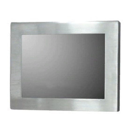
1.3 Brief Description of APC-3x97B APC-3X97B series comes with IP65 certificated and is powered by Intel Atom D2550 to provide low power consumption. The stainless steel chassis design makes it exceptionally suitable for strict hygiene regulations for food/chemical industry, medical, restaurant/kitchen applications, storage management and outdoor /information segment and so on. -
Page 11: Chapter 2 Hardware
1 x RS-232/RS-422/RS-485, DB9 connector for external (COM1) pin 9 w/5V/12V/Ring select Serial 1 x RS232 port, DB9 connector for external (COM2) pin 9 w/5V/12V/Ring select 1 x RS422/485 header via CN2 (COM3) 2 x UART via CN3 (COM5,COM6) APC-3x97B User Manual... - Page 12 Software programmable 1 – 255 second by Super I/O Timer Operating: -20℃ to 70℃ Temperature Storage: -40℃ to 85℃ Humidity 5% - 95%, non-condensing, operating Power 12V /0.95A (Intel Atom N2600 processor with 2GB DDR3 Consumption DRAM) Meet CE/FCC class A EMI/EMS APC-3x97B User Manual...
-
Page 13: Figure 2.1: Mainboard Dimensions
(units :mm) Figure 2.1: Mainboard Dimensions APC-3x97B User Manual... -
Page 14: Installations
LVDS interface. To satisfy the special needs of high-end customers, CN1 and CN2 and CN3 richer extension functions. The product is widely used in various sectors of industrial control. 2.2.1 Jumpers Setting and Connectors Board Top Figure 2.2: Jumpers and Connectors Location_ Board Top Board Bottom APC-3x97B User Manual... -
Page 15: Jumpers Setting And Connectors
Figure 2.3: Jumpers and Connectors Location_ Board Bottom 2.3 Jumpers Setting and Connectors 1. JP5: (2.0mm Pitch 1X2 box Pin Header),ATX Power and Auto Power on jumper setting. Mode Open ATX Power Close Auto Power on (Default) APC-3x97B User Manual... - Page 16 Pin3 6. VGA1: (CRT 2.0mm Pitch 2X6 Pin Header), Video Graphic Array Port, Provide 2x6Pin cable to VGA Port. Signal Name Pin# Pin# Signal Name CRT_RED Ground CRT_GREEN Ground CRT_BLUE Ground CRT_H_SYN CRT_DDCDAT CRT_V_SYNC CRT_DDCCL Ground Ground APC-3x97B User Manual...
- Page 17 (Switch),COM1 setting, it provides selectable RS232 or RS422 or RS485 serial signal output. Function RS_422 Pin# RS232 OFF: Pin1, Pin2, Pin3, Pin4, (Default) Pin5 RS422 Pin1, Pin2, Pin3, Pin4, (option) Pin5 RS485 Pin1, Pin2, Pin3, Pin4, (option) Pin5 Note: Must keep the setting with BIOS setting. APC-3x97B User Manual...
-
Page 18: Chapter 3 Bios Setup
RTS (Request To Send) CTS (Clear To Send) JP1 select Setting (RI/5V/12V) BIOS Setup: Advanced/W83627UHG Super IO Configuration/Serial Port 1 Configuration【RS-232】 RS422 (option): Pin# Signal Name 422_RX+ 422_RX- 422_TX- 422_TX+ Ground BIOS Setup: Advanced/W83627UHG Super IO Configuration/Serial Port 1 Configuration【RS-422】 APC-3x97B User Manual... - Page 19 (2.0mm Pitch 2x3 Pin Header), COM2 jumper setting, pin 1~6 are used to select signal out of pin 9 of COM2 port. JP2 Pin# Function Close 1-2 COM1 RI (Ring Indicator) (default) Close 3-4 COM1 Pin9=+5V (option) Close 5-6 COM1 Pin9=+12V (option) APC-3x97B User Manual...
- Page 20 RI (Ring Indicator) 16. LED3: LED STATUS. Green LED for Touch Power status. 19 SATA1: SATA Connectors, one SATA connectors are provided, with transfer (SATA 7Pin+15Pin), speed up to 3.0Gb/s. 20 SD1: (SD card socket),Secure Digital Memory Card socket. APC-3x97B User Manual...
- Page 21 ACTIVE LED (yellow) respectively located at the left-hand and right-hand side of the Ethernet port indicate the activity and transmission state of LAN. 26. BUZ1: Onboard buzzer. 27 LED1: LED STATUS. Green LED for Motherboard Power status. APC-3x97B User Manual...
- Page 22 (UART) COM5_DTR DSRCOM5_RTS- COM5_DSR DTRCOM5_CTS- GPIO24 ICH_GPIO24 ICH_GPIO13 GPIO13 GPIO26 ICH_GPIO26 ICH_GPIO27 GPIO27 Ground Ground PE1_TX_N0 PE1_TX_P0 PE1_RX_N0 PE1_RX_P0 PCIE PCIE Ground Ground CLK_100M_PE1_P CLK_100M_PE1_N PLTRST_BUF- PM_PCIE_WAKE SMBUS SMB_CLK_S SMB_DATA_S SMBUS PE1_CLKRE Ground PCIE PCIE 3P3V_S5 3P3V_S5 APC-3x97B User Manual...
- Page 23 3P3V_S5 3P3V_S5 12V_S0 12V_S0 APC-3x97B User Manual...
-
Page 24: Operations After Post Screen
BIOS Date: 12/17/2012 02:22:46 Ver: 7106V002 Press 〈DEL〉or〈F2〉to enter setup After optimizing and exiting CMOS Setup, the POST screen displayed for the first time is as follows and includes basic information on BIOS, CPU, memory, and storage devices. APC-3x97B User Manual... -
Page 25: Bios Setup Utility
Version 2.15.1226. Copyright (C) 2012 American Megatrends , Inc. 3.3 Main Settings BIOS Information Intel Reference Code BIOS Vendor American Megatrends Version Core Version 4.6.5.3 Compliancy UEFI 2.3; PI 1.2 Project Version 7106V002 Build Date and Time 12、17、2012 03:22:46 ►Intel RC Version APC-3x97B User Manual... - Page 26 Second : 0 to 59 System Date: Set the system date, the date format is: Note that the ‘Day’ automatically changes when you set the date. Day: Month: 01 to 12 Date: 01 to 31 Year: 1998 to 2099 APC-3x97B User Manual...
-
Page 27: Advanced Settings
[32 PCI Bus Clocks] [64 PCI Bus Clocks] [96 PCI Bus Clocks] [128 PCI Bus Clocks] [160 PCI Bus Clocks] [192 PCI Bus Clocks] [224 PCI Bus Clocks] [248 PCI Bus Clocks] VGA Palette Snoop: [Disabled] [Enabled] PERR# Generation: APC-3x97B User Manual... - Page 28 S3 Video Repost: [Disabled] [Enabled] 3.4.3 CPU Configuration Processor Type Intel(R) Atom(TM) CPU N2600 EMT64 Not Supported Processor Speed 1600 MHz System Bus Speed 400MHz Ratio Status Actual Ratio System Bus Speed 400 MHz Processor Stepping 30661 Microcode Revision APC-3x97B User Manual...
- Page 29 Active Trip Point Hi [71C] Passive Trip Point [95] Passive TC1 Value Passive TC2 Value Passive TSP Value 3.4.5 IDE Configuration SATA Port0 Not Present SATA Port1 Not Present SATA Controller(S): [Enabled] [Disabled] Configure SATA as: [IDE] APC-3x97B User Manual...
- Page 30 [40 sec] Device power-up delay [Auto] [Manual] Mass Storage Devices: Multiplecard Reader 1 [Auto] [Floppy] [Forced FDD] [Hard Disk] [CD-ROM] 3.4.7 W83627UHG Super IO Configuration W83627UHG Super IO ch W83627UHG Serial Port 1 Configuration UART Mode Selection: [RS-232] APC-3x97B User Manual...
- Page 31 VCC5V : +5.216 V VSB5 : +5.203 V VBAT : +3.334 V 3.4.9 Serial Port Console Redirection COM0 Console Redirection [Enabled] [Disabled] Console Redirection Settings Serial Port for Out-of-Band Management/ Windows Emergency Management Services (EMS) Console Redirection APC-3x97B User Manual...
- Page 32 [Enabled] [Disabled] CPU C state Report [Enabled] [Disabled] Enhanced C state [Enabled] [Disabled] CPU Hard C4E [Enabled] [Disabled] CPU C6 state [Enabled] [Disabled] C4 Exit Timing [Fast] [Default] [Slow] C-state POPDOWN [Enabled] [Disabled] C-state POPUP [Enabled] [Disabled] APC-3x97B User Manual...
-
Page 33: Chipset Settings
►Memory Frequency and Timing ►Intel IGD Configuration ******* Memory Information ******* Memory Frequency 800 MHz(DDR3) Tot al Memory 2048 MB DIMM#0 Not Present DIMM#1 2048 MB Memory Frequency and Timing MRC Fast Boot [Enabled] [Disabled] Max TOLUD [Dynamic] [1GB] [1.25GB] APC-3x97B User Manual... - Page 34 LCD Panel Type [VBIOS Default] [640x480,18bit] [800x480,18bit] [800x600,18bit] [1024x600,18bit ] [1024x768,18bit ] [1280x768,18bit ] [1280x800,18bit ] [1280x1024,18bit] [1366x768,18bit] [1024x768,24bit] [1280x768,24bit] [1280x800,24bit] [1280x1024,24bit] Panel Scaling [Auto] [Force Scaling] [off] [Maintain Aspect Ratio] Active LFP [LVDS] [No LVDS] [EDP] APC-3x97B User Manual...
- Page 35 Back light Control Lev [Auto] [Disabled] [Level 8] [Level 1] [Level 2] [Level 3] [Level 4] [Level 5] [Level 6] [Level 7] [Level 8] [Level 9] [Level 10] [Level 11] [Level 12] [Level 13] [Level 14] [Level 15] APC-3x97B User Manual...
- Page 36 [Disabled] PCI-Exp. High Priorit [Disabled] [Enabled] High Precision Event Timer Configuration High Precision Timer [Enabled] [Disabled] SLP_S4 Assertion Widt [1-2 Seconds] [2-3 Seconds] [3-4 Seconds] [4-5 Seconds] Restore AC Power Loss [Last State] [Power off] [Power on] APC-3x97B User Manual...
-
Page 37: Boot Settings
Boot Option #2 […] F3:Optimized Defaults Hard Drive BBS Priorities F4:Save and Exit ►CSM Parameters ESC Exit Version 2.15.1226. Copyright (C) 2012 American Megatrends , Inc. Setup Prompt Timeout Bootup Numlock State [On] [off] Quiet Boot [Disabled] APC-3x97B User Manual... - Page 38 Interrupt 19 Capture [Immediate] [Postponed] Boot Option #1 Boot Option #2 …… Sets the system boot order [SATA PM:*** … ] Hard Drive BBS Priorities Boot Option #1 SATA PM:***… ****** Disabled CSM Parameters Launch CSM [Always] APC-3x97B User Manual...
- Page 39 Launch PXE OpROM poli [Do not Launch] [UEFI only] [Legacy only] Launch Storage OpROM [Legacy only] [Do not Launch] [UEFI only] Launch Video OpROM po [Do not Launch] [UEFI only] [Legacy only] Other PCI device ROM [UEFI OpROM] [Legacy OpROM] APC-3x97B User Manual...
-
Page 40: Security Settings
Enter key. You may press Esc key to abandon password entry operation. To clear the password, just press Enter key when password input window pops up. A confirmation message will be shown on the screen as to whether the password will be disabled. APC-3x97B User Manual... -
Page 41: Save And Exist Settings
Note: Due to limited address length of BIOS, only a portion of panel parameters are listed in BIOS Setup. If the connected panel is not included in the parameter list, display problem will occur. In this case, Please do not change BIOS setup. APC-3x97B User Manual... - Page 42 V02.61 © Copyright 1985-2006 American Mega trends , Inc. Memory Remap Feature: [Enabled] [Disabled] Memory Hole: [Disabled] [15MB-16MB] Initate Graphic Adapter: Select which graphics controller to use as the primary boot device. [IGD] [PCI/IGD] IGD Graphics Mode Select: [Enabled, 64MB] [Disabled] APC-3x97B User Manual...
- Page 43 F10 Save and Exit Backlight Image Adaptation ESC Exit [VBIOS-Default] V02.61 © Copyright 1985-2006 American Mega trends , Inc. DVMT Mode Select: [DVMT Mode] [FIXED Mode] DVMT/FIXED Memory Size: [256MB] [128MB] [Maximum DVMT] Boot Display Device: [BIOS-Default] [CRT] APC-3x97B User Manual...
- Page 44 [BLC Enabled] Backlight Control Control: [Level5] [Level0] [Level1] [Level2] [Level3] [Level4] [Level6] [Level7] Note: Panel support PWM Function. Backlight Control Mode: [DC] [PWM] Backlight Image Adaptation: [VBIOS-Default] [BIA Disabled] [BIA Enabled at Level1] [BIA Enabled at Level2] APC-3x97B User Manual...
-
Page 45: South Bridge Configuration
Save Changes and Exit Save & Exit Setup save Configuration and exit ? [Yes] [No] Discard Changes and Ext Exit Without Saving Quit without saving? [Yes] [No] Save Changes and Reset Save & reset Save Configuration and reset? [Yes] APC-3x97B User Manual... - Page 46 Load Optimized Defaults Load optimized Defaults? [Yes] [No] Save user Defaults Save Values as User Defaults Save configuration? [Yes] [No] Restore user Defaults Restore User Defaults Restore User Defaults? [Yes] [No] Launch EFI Shell from filesystem device WARNING Not Found [ok] APC-3x97B User Manual...
-
Page 47: Exit Options
F10 key can be used for this operation) [OK] [Cancel] Discard Changes and Exit: Discard Changes and Exit setup? ESC key can be used for this operation) [OK] [Cancel] Discard Changes: Discard changes? F7 key can be used for this operation) [OK] [Cancel] APC-3x97B User Manual... - Page 48 Load Optimized Defaults: Load Optimized Defaults? F9 key can be used for this operation) [OK] [Cancel] Load Fail-Safe Defaults: Load Fail-Safe Defaults? F9 key can be used for this operation) [OK] [Cancel] APC-3x97B User Manual...
-
Page 49: Chapter 4 Installation Of Drivers
VGA driver, LAN drivers, Audio driver Installation instructions are given below. Important Note: After installing your Windows operating system (Windows 7), you must install first the Intel Chipset Software Installation Utility before proceeding with the installation of drivers. APC-3x97B User Manual... -
Page 50: Intel Chipset Driver
4.1 Intel Chipset Driver To install the Intel chipset driver, please follow the steps below. Step 1. Select Intel (R) Chipset NM10 Express from the list Step 2. Click Next to setup program. APC-3x97B User Manual... - Page 51 Step 3. Read the license agreement. Click Yes to accept all of the terms of the license agreement. Step 4. Click Next to continue. APC-3x97B User Manual...
- Page 52 Step 5. Click Next. Step 6. Select Yes, I want to restart this computer now. Click Finish, then remove any installation media from the drives. APC-3x97B User Manual...
-
Page 53: Intel Graphics Media Accelerator Driver
4.2 Intel Graphics Media Accelerator driver To install the VGA drivers, follow the steps below to proceed with the installation. Step 1.Select Intel(R) VGA Chipset Driver. Step 2. Tick Automatically run WinSAT and enable the Windows Aero desktop theme(if supported). Click Next. APC-3x97B User Manual... - Page 54 Step 3. Read license agreement. Click Yes. Step 4. Click Next. APC-3x97B User Manual...
- Page 55 Step 5. Click Next. Step 6. Select Yes, I want to restart this computer now. Click Finish. APC-3x97B User Manual...
-
Page 56: Intel (R) Network Adapter
4.3 Intel (R) Network Adapter To install the Intel (R) Network Adapter device driver, please follow the steps below. Step 1. Select Realtek RTL8111D Driver. Step 2. Click Next to continue. APC-3x97B User Manual... - Page 57 Step 3. Click Install to begin the installation. Step 4. Click Finish to exist the wizard. APC-3x97B User Manual...
-
Page 58: Realtek Alc662 Hd Audio Driver Installation
4.4 Realtek ALC662 HD Audio Codec Driver Installation To install the Realtek ALC662 HD Audio Codec Driver, please follow the steps below. Step 1. Select Realtek AL662 Audio Codec Driver from the list Step 2. Click Next to continue. APC-3x97B User Manual... - Page 59 Step 3. Click Yes, I want to restart my computer now. Click Finish to complete the installation. APC-3x97B User Manual...
-
Page 60: Chapter 5 Touch Screen Installation
If you have an older version of the PenMount Windows 2000/XP driver installed in your system, please remove it first. Follow the steps below to install the PenMount DMC6000 Windows 2000/XP driver. Step 1. Insert the product CD, the screen below would appear. Click touch panel driver. APC-3x97B User Manual... - Page 61 Step 2. Click Next to continue. Step 3. Read the license agreement. Click I Agree to agree the license agreement. APC-3x97B User Manual...
- Page 62 Step 4. Choose the folder in which to install PenMount Windows Universal Driver. Click Install to start the installation. Step 5. Wait for installation. Then click Next to continue. APC-3x97B User Manual...
- Page 63 Step 6. Click Continue Anyway. Step 7. Click Finish to complete installation. APC-3x97B User Manual...
-
Page 64: Software Functions
‘Advanced Calibration’ adjusts aging touch screens. Standard Calibration Click this button and arrows appear pointing to red squares. Use your finger or stylus to touch the red squares in sequence. After the fifth red point calibration is complete. To skip, press APC-3x97B User Manual... - Page 65 -calibration 0 ( Standard Calibration) Dmcctrl.exe - calibration ($) 0= Standard Calibration 4=Advanced Calibration 4 9=Advanced Calibration 9 16=Advanced Calibration 16 25=Advanced Calibration 25 Step 1. Please select a device then click “Configure”. You can also double click the device too. APC-3x97B User Manual...
- Page 66 Step 2.Click “Standard Calibration” to start calibration procedure APC-3x97B User Manual...
- Page 67 NOTE: The older the touch screen, the more Advanced Mode calibration points you need for an accurate calibration. Use a stylus during Advanced Calibration for greater accuracy. Please follow the step as below: Step 3.Come back to “PenMount Control Panel” and select Tools then click Advanced Calibration. APC-3x97B User Manual...
- Page 68 Step 4. Select Device to calibrate, then you can start to do Advanced Calibration. NOTE: Recommend to use a stylus during Advanced Calibration for greater accuracy. APC-3x97B User Manual...
- Page 69 Setting APC-3x97B User Manual...
- Page 70 About This panel displays information about the PenMount controller and driver version. APC-3x97B User Manual...
- Page 71 Please note once you turn on this function the rotating function is disabled. Enable the multiple display function as follows: 1. Check the Enable Multiple Monitor Support box; then click Map Touch Screens to assign touch controllers to displays. APC-3x97B User Manual...
- Page 72 4. Touching all screens completes the mapping and the desktop reappears on the monitors. 5. Select a display and execute the “Calibration” function. A message to start calibration appears. Click OK. APC-3x97B User Manual...
- Page 73 This panel displays information about the PenMount controller and this driver version. PenMount Monitor Menu Icon The PenMount monitor icon (PM) appears in the menu bar of Windows 2000/XP system when you turn on PenMount Monitor in PenMount Utilities. APC-3x97B User Manual...
- Page 74 2. Choose the rotate function (0°, 90°, 180°, 270°) in the 3rd party software. The calibration screen appears automatically. Touch this point and rotation is mapped. NOTE: The Rotate function is disabled if you use Monitor Mapping APC-3x97B User Manual...
Need help?
Do you have a question about the APC-3x97B and is the answer not in the manual?
Questions and answers