Table of Contents
Advertisement
Quick Links
APC-3098/3298A/3598A
Panel PC User Manual
Release Date
_
Revision
Jun. 2011
V1.0
® 2011 Aplex Technology, Inc.
All Rights Reserved.
Published in Taiwan
Aplex Technology, Inc.
15F-1, No.186, Jian Yi Road, Zhonghe District, New Taipei City 235, Taiwan
Tel: 886-2-82262881 Fax: 886-2-82262883 E-mail:
aplex@aplex.com.tw
URL:
www.aplex.com.tw
APC-3X98(A) User Manual
1
Advertisement
Table of Contents

Related Manuals for Aplex APC-3098


Summary of Contents for Aplex APC-3098
- Page 1 Panel PC User Manual Release Date Revision Jun. 2011 V1.0 ® 2011 Aplex Technology, Inc. All Rights Reserved. Published in Taiwan Aplex Technology, Inc. 15F-1, No.186, Jian Yi Road, Zhonghe District, New Taipei City 235, Taiwan Tel: 886-2-82262881 Fax: 886-2-82262883 E-mail: aplex@aplex.com.tw...
-
Page 2: Warning
Warning!____________________________________ Safety & Warranty 1. Read these safety instructions carefully. 2. Keep this user's manual for later reference. 3. Disconnect this equipment from any outlet before cleaning. Do not use liquid or spray detergents for cleaning. Use a damp cloth. 4. -
Page 3: Disclaimer
Disclaimer This information in this document is subject to change without notice. In no event shall Aplex Technology Inc. be liable for damages of any kind, whether incidental or consequential, arising from either the use or misuse of information in this document or in any related materials. -
Page 4: Table Of Contents
4.2 Intel Graphics Media Accelerator Driver...…………………..…………..50 4.3 Intel 8257L Gbe LAN Device Driver………………………………….….53 4.4 Realtek HD Audio Driver Installation…….…………..…………………56 Chapter 5 Touch Screen Installation 5.1 Introduction to Controller Board..…………………………….……………58 5.2 Windows 2000/XP USB Driver Installation………………….………..….58 Figures Figure 1.1: APC-3098 Dimensions………………………………………..…..8 APC-3X98(A) User Manual... - Page 5 Figure 1.2: APC-3298A Dimensions……………………..……………………..9 Figure 1.3: APC-3598A Dimensions…………………….…………………….10 Figure 1.4: Front View ………………………………………………………….11 Figure 1.5: Rear View…………………………………………………………...11 Figure 2.1: Mainboard Overview…………………………………………..12 Figure 5.1 Birdeye’s View of Control Board………………..…………………58 APC-3X98(A) User Manual...
-
Page 6: Specifications
Chapter 1 System 1.1 Specifications Specs APC-3098 APC-3298A APC-3598A Intel Atom Z510p 1.1 GHz FSB 400 MHz, Z530p 1.6 GHz FSB 533 MHz for option Chipset Intel US15WP System Memory On board 1 GB DDR2 400 MHz Graphic Intel integrated Graphics GMA500 Standard I/O:... - Page 7 Certificate CE/FCC Class A APC-3X98(A) User Manual...
-
Page 8: Dimensions
1.2 Dimensions Figure 1.1: Dimensions of the APC-3098 APC-3X98(A) User Manual... -
Page 9: Figure 1.2: Apc-3298A Dimensions
Figure 1.2: Dimensions of the APC-3298A APC-3X98(A) User Manual... -
Page 10: Figure 1.3: Apc-3598A Dimensions
Figure 1.3: Dimensions of the APC-3598A APC-3X98(A) User Manual... -
Page 11: Brief Description
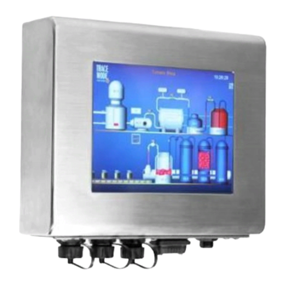
1.3 Brief Description of the APC-3098/3298A/3598A The APC-3098/3298A/3598A is a fanless design panel PC, which comes with an 8-inch (luminance of 350 cd/m²)/12-inch (luminance of 350 cd/m²)/15-inch (luminance of 350 cd/m²) TFT LCD. It is powered by an Intel Atom Z510P Processor. The industrial panel PC also features two COM ports, two USB 2.0 ports, one 2.5”... -
Page 12: Chapter 2 Hardware
Chapter 2 Hardware 2.1 Mainboard Figure 2.1: Mainboard Overview APC-3X98(A) User Manual... -
Page 13: Jumpers And Connectors Location
2.2 Jumpers and Connectors Location 2.3 Jumpers Setting and Connectors 1. JP5: (2.0mm Pitch 1X2 Pin Header), ATX Power and AT Power setting jumper. Mode Open ATX Power Mode Close AT Power Mode 2. PWR1: (5.0mm 1x2 Pin Connector),DC9V~30V System power input connector。 Pin# Signal Name +DC9V~DC30V... - Page 14 Ground Note: Make sure that the voltage of power supply is DC9V~30V before power on, or it may cause boot up failure and even system damage. 3. BAT1: (1.25mm Pitch 1X2 box Pin Header) 3.0V Li battery is embedded to provide power for CMOS.
- Page 15 3-5 ( Close) 4-6 ( Close) RS422 9-11 ( Close) 10-12 ( Close) 17-18 (Close) 3-5 ( Close) 4-6 ( Close) RS485 15-16 (Close) 7. COM1 (Type DB9), Rear serial port, standard DB9 serial port is provided to make a direct connection to serial devices.
- Page 16 RXD (Received Data) TXD (Transmit Data) DTR (Data Terminal Ready) Ground DSR (Data Set Ready) RTS (Request To Send) CTS (Clear To Send) JP3 Setting: Pin1-2 : RI (Ring Indicator) (default) Pin3-4 : 5V Standby power (option) Pin5-6: 12V Standby power (option) 9.
- Page 17 Note: Pin6 is backlight control signal, support DC or PWM mode, mode select at BIOS CMOS menu. LVDS1: For 18/24 bit LVDS output connector, fully supported by Intel US15W chipset, the interface features dual channel 18/24-bit output. Model name of the interface connector is Hirose DF13-40DP-1.25V.
- Page 18 Expansion SMB bus. ·RS232(COM2,COM4): Expansion serial ports are provided to make a direct connection to serial devices. Function Signal Name Pin# Pin# Signal Name Functio 5V_USB 5V_USB USB1 USB1 USB1_N USB1_P Ground Ground MS_CLK MS_CLK PS/2 MS PS/2 MS_DATA KB_DATA 5V_F_AUDIO GND_AUD LINE_OUT_L...
- Page 19 HD LED+ POWER LED+ HD LED- POWER LED- Ground PWR_ON RESET+ Ground WAN LED- WAN LED+ Pin1-3: HDD LED, They are used to connect hard disk activity LED. The LED blinks when the hard disk is reading or writing data. Pin2-4: POWER LED, They are used to connect power LED.
- Page 20 18. JP2: (2.0mm Pitch 2x3 Pin Header), SATA1/SATA2/CF Devices Master or slave jumper setting. SATA1/ SATA2/ CF devices can only be used two at the same time, and the Master device can be set one only. While using SATA1/SATA2 devices at the same time, one of the devices must be set as Master.
- Page 21 □ TB515 (option): ASB-B705 SDVO1 connected Card, Support SDVO to CRT display and HDMI TV display TB515 Location VGA2 Port Signal Name: VGA2 CRT_BLUE BLUE CRT_GREEN GREEN CRT_RED CRT_DDCCLK DDCCLK CRT_DDCDATA DDCDATA CRT_VSY NC VSY NC CRT_HSY NC HSY NC CVBS_SY NC_OUT DF14A-10P-1.25H APC-3X98(A) User Manual...
- Page 22 B_CLK+ A_CLK+ 2LDDC_DATA 2LDDC_CLK DDC_DATA DDC_CLK 2LB_D3_N 2LA_D3_N B_D3- A_D3- 2LB_D3_P 2LA_D3_P B_D3+ A_D3+ Aplex, 10.07.29 DF13-40DP-1.25V LVDS2 Backlight control connector for INVERTER1. 22. H7/H9 : SDVO CARD SCREW HOLES, two screw holes for SDVO card assemble. APC-3X98(A) User Manual...
- Page 23 23. H3/H4/H5/H6: Intel Atom Z530P(or Z510P) CPU+ US15W Heat Sink SCREW HOLES, Four screw holes for Intel CPU and US15W Heat Sink assemble. Standby Power Good status 。 LED2: LED1/LED2 LED STATUS. LED1:Motherboard CPU Power Good status. Motherboard 25. USB67: (2.0mm Pitch 2x5 Pin Header),Front USB connector, it provides two USB ports via a dedicated USB cable, speed up to 480Mb/s.
-
Page 24: Chapter 3 Bios Setup
Chapter 3 BIOS Setup 3.1 Operations after POST Screen After CMOS discharge or BIOS flashing operation, the system will display the following screen for your further operation. Press Delete key to enter CMOS Setup. AMIBIOS© 2006 American Mega trends , Inc. BIOS Date: 02/23/11 23:27:33 Ver: 08.00.15 CPU : Intel(R) Atom(TM) CPU Z510... -
Page 25: Bios Setup Utility
Please select boot device: Network: IBA GE Slot 0100 v1353 ↑and ↓ to move selection ENTER to select Boot device ESC to boot using defaults 3.2 BIOS SETUP UTILITY Press [Del] key to enter BIOS Setup utility during POST, and then a main menu containing system summary information will appear. -
Page 26: System Overview
System Date [Wed ESC Exit 02/23/2011] LO-Module:0D2.023x, Hi-Module:0d2.016x v02.61 © Copyright 1985-2006 American Megatrends , Inc. 3.3 System Overview BIOS SETUP UTILITY Main Advanced PCIPnP Boot Security Chipset Exit System Overview User [ENTER],[TAB] AMIBIOS or [SHIFT-TAB] to Version : 08.00.15 Select a field Build Date : 02/23/11 Use[+] or [-] to... -
Page 27: Advanced Settings
3.4 Advanced Settings BIOS SETUP UTILITY Main Advanced PCIPnP Boot Security Chipset Exit Advanced Settings Configure CPU WARNING: Setting wrong values In below sections may cause system to malfunction. ► CPU Configuration ► IDE Configuration ► Super IO Configuration ► ACPI Configuration ←... - Page 28 Max CPUID Value Limit [Disabled] +- Charge Field Intel (R) Virtualization Tech [Enabled] F1 General Help Execute-Disable Bit Capability [Enabled] F10 Save and Exit Hyper Threading Technology [Enabled] ESC Exit Intel(R) SpeedStep (tm) tech [Disabled] Intel(R) C-SATAE tech [Disabled] V02.61 © Copyright 1985-2006 American Mega trends , Inc. Hardware Prefetcher: [Enabled] [Disabled]...
- Page 29 ATA/IDE Configuration [Compatible] Disabled Compatible ► Primary IDE Master : [Not Detected] ► Primary IDE Slaver ← Select Screen : [Not ↑↓ Select Item Detected] +- Charge Field F1 General Help Hard Disk Write Protect [Disabled] F10 Save and Exit IDE Detect Time Out (Sec) [35] ESC Exit...
- Page 30 Serial Port1 Address [3F8] Serial Port Base Serial Port1 Mode [RS-232] Address. Serial Port2 Address [2F8] Serial Port3 Address [3E8] Serial Port3 IRQ [IRQ4] Serial Port4 Address [2E8] Serial Port4 IRQ [IRQ3] ← Select Screen ↑↓ Select Item +- Charge Field F1 General Help F10 Save and Exit ESC Exit...
- Page 31 [Chipset ACPI Configuration]: APIC ACPI SCI IRQ: [Disabled] [Enabled] USB Device Wakeup From S3/s4: [Disabled] [Enabled] 3.4.5 MPS Configuration BIOS SETUP UTILITY Advanced MPS Configuration Select MPS MPS Revision [1.4] Revision ← Select Screen ↑↓ Select Item +- Charge Field F1 General Help F10 Save and Exit ECS Exit...
-
Page 32: Smbios Configuration
General Help F10 Save and Exit ESC Exit V02.61 © Copyright 1985-2006 American Mega trends , Inc. Active State Power Management: [Disabled] [Enabled] 3.4.7 Smbios Configuration BIOS SETUP UTILITY Advanced Smbios Configuration SMBIOS SMI Wrapper Smbios Smi Support [Enabled] Support for PnP Func 50h-54h ←... -
Page 33: Advanced Pci/Pnp Settings
option disables legacy USB Devices Enabled : support if no USB 1Keyboard devices are connected Legacy USB Support [Enabled] ← USB2.0 Controller Mode [HiSpeed] Select Screen ↑↓ BIOS EHCI Hand-Off [Enabled] Select Item Charge Field General Help F10 Save and Exit ESC Exit V02.61 ©... - Page 34 Clear NVRAM [No] Plug & Play O/S [No] PCI Latency Timer [64] Allocate IRQ to PCI VGA [Yes] Palette Snooping [Disabled] PCI IDE BusMaster [Disabled] OffBoard PCI/ISA IDE Card [Auto] ← Select Screen IRQ3 ↑↓ Select Item [Available] +- Charge Field IRQ4 F1 General Help [Available]...
- Page 35 [248] Allocate IRQ to PCI VGA: [Yes] [No] Palette Snooping: [Disabled] [Enabled] PCI IDE BusMaster: [Disabled] [Enabled] OffBoard PCI/ISA IDE Card: Some PCI IDE cards may require this to be set to the PCI slot number that is holding the card. Auto:Works for most PCI IDE Cards. [Auto] [PCI Slot1] [PCI Slot2]...
-
Page 36: Boot Settings
[32k] [64k] 3.6 Boot Settings BIOS SETUP UTILITY Main Advanced PCIPnP Boot Security Chipset Exit Boot Settings Configure Settings During System Boot ► Boot Setting Configuration ► Boot Device Priority ► Hard Disk Drives ← Select Screen ↑↓ Select Item Enter Go to sub screen F1 General Help F10 Save and Exit... -
Page 37: Security Settings
AddOn ROM Display Mode: Set display mode for Option ROM. [Force BIOS] [Keep Current] Bootup Num-Lock: Select Power-on state for Numlock. [On] [Off] Wait For ‘F1’ If Error: Wait for F1 key to be pressed if error occurs. [Enabled] [Disabled] Hit ‘DEL’Messgae Display : Displays “press”... - Page 38 Change User Password ← Boot Sector Virus Protection [Disabled] Select Screen ↑↓ Select Item Enter Charge General Help F10 Save and Exit ESC Exit V02.61 © Copyright 1985-2006 American Mega trends , Inc. Change Supervisor Password: Install or Change the password. Change User Password: Install or Change the password.
-
Page 39: Advanced Chipset Settings
3.8 Advanced Chipset Settings BIOS SETUP UTILITY Main Advanced PCIPnP Boot Security Chipset Exit Advanced Chipset Settings Configure North Bridge WARNING: Setting wrong values in below feature sections may cause system to malfunction ► North Bridge Configuration ← Select Screen ►... - Page 40 V02.61 © Copyright 1985-2006 American Mega trends , Inc. Primary Graphics Adapter: [PCIe/IGD] [IGD] Integrated Graphics Mode Selec: [Enabled ,4MB] [Enabled ,1MB] [Enabled ,8MB] [Disabled] Boot Display Configuration: BIOS SETUP UTILITY Chipset Boot Display Configuration Options Boot Display Device [Auto] Auto Local Flat Panel Scaling [Auto]...
- Page 41 External CRT External LVDS Flat Panel Type: [1024x 768 18bit ] [640x480 18bit ] [800x600 18bit ] [1280x768 18bit ] [1280x800 18bit ] [1024x 768 24bit ] Backlight Control Support [VBIOS-Default] [Both BLC & BIA Disabled] [BLC Enabled] Panel Backlight Control: [Level9] [Level0] [Level1]...
- Page 42 [DPST Disabled] [DPST Enabled at Level] [DPST Enabled at Leve2] [DPST Enabled at Leve3 [DPST Enabled at Leve4] [DPST Enabled at Leve5] TV Standard: [VBIOS-Default] [NTSC] [PAL] [SECAM] [SMPTE240M] [ITU-R television] [SMPTE296M] [CEA 7702] [CEA 7703] 3.8.2 South Bridge Configuration: BIOS SETUP UTILITY Chipset South Bridge Chipset Configuration...
- Page 43 [8 USB Ports] [Disabled], [2 USB Ports] [4 USB Ports] [6 USB Ports] USB 2.0 Controller: [Enabled] [Disabled] USB Client Controller: [Disabled] [Enabled] SDIO Controller: [Enabled] [Disabled] Audio Controller Codec: [Auto] [Azalia] [Disabled] Reserved Page Route: [LPC] [PCI] PCIE Ports Configuration: PCIE Port 0: [Auto] [Enabled]...
-
Page 44: Exit Options
Exit Options BIOS SETUP UTILITY Main Advanced PCIPnP Boot Security Chipset Exit Exit Options Exit system setup Save Changes and Exit after saving the Discard Changes and Exit changes Discard Changes F10 key can be used For this operation Load Optimal Defaults Load Failsafe Defaults ←... - Page 45 Load Optimized Defaults: Load Optimized Defaults? F9 key can be used for this operation) [OK] [Cancel] Load FailSafe Defaults: Load FailSafe Defaults? F9 key can be used for this operation) [OK] [Cancel] APC-3X98(A) User Manual...
-
Page 46: Chapter 4 Installation Of Drivers
Chapter 4 Installation of Drivers This chapter describes the installation procedures for software and drivers under the windows XP. The software and drivers are included with the motherboard. The contents include Intel chipset driver VGA driver LAN drivers Audio driver Installation instructions are given below. -
Page 47: Intel Chipset Driver
4.1 Intel Chipset Driver To install the Intel chipset driver, please follow the steps below. Step 1: Select Chipset from the list Follow the step-by-step installation process to install the LMS_SQL driver. APC-3X98(A) User Manual... - Page 48 APC-3X98(A) User Manual...
- Page 49 Click Finish, When the installation process is complete, the Setup Complete screen appears. See as picture. APC-3X98(A) User Manual...
-
Page 50: Intel Graphics Media Accelerator Driver
4.2 Intel Graphics Media Accelerator Driver To install the VGA drivers, follow the steps below to proceed with the installation. 1. Click Intel(R) US15W Chipset Family Graphics Driver. Follow the step-by-step installation process to install the Graphics Media Accelerator driver. APC-3X98(A) User Manual... - Page 51 APC-3X98(A) User Manual...
- Page 52 Click FINISH; A Driver Installation Complete. APC-3X98(A) User Manual...
-
Page 53: Intel 8257L Gbe Lan Device Driver
4.3 Intel 8257L Gbe LAN Device Driver To install the Intel R 8257L Gbe Gigabit LAN connect device driver, please follow the steps below. Select LAN from the list Follow the step-by-step installation process to install the LAN driver. APC-3X98(A) User Manual... - Page 54 APC-3X98(A) User Manual...
- Page 55 Click FINISH; A Driver Installation Complete. APC-3X98(A) User Manual...
-
Page 56: Realtek Hd Audio Driver Installation
4.4 Realtek HD Audio Driver Installation To install the Realtek High Definition (HD) Audio driver, please follow the steps below. Select Audio from the list Follow the step-by-step installation process to install the Realtek HD Audio driver. APC-3X98(A) User Manual... - Page 57 Click FINISH; A Driver Installation Complete. APC-3X98(A) User Manual...
-
Page 58: Chapter 5 Touch Screen Installation
Chapter 5 Touch Screen Installation This chapter describes how to install drivers and other software that will allow your PenMount 6000 Controller Board to work with different operating systems. NOTE: PenMount USB drivers support up to 15 USB controllers. 5.1 Introduction to Touch Screen Controller Board PenMount 6300 USB control board is a touch screen control board designed for USB interface and specific for 4, 5, 8-wire touch screens. -
Page 59: Installing Software
When the system first detects the controller board, a screen appears that shows “Unknown Device”. Do not use this hardware wizard. Press Cancel. 2. Insert the Aplex product CD install setup.exe. the screen below would appear. Click touch panel driver APC-3X98(A) User Manual... - Page 60 3. A License Agreement appears. Click “I Agree…” and “Next” 4. Ready to Install the Program. Click “Install” APC-3X98(A) User Manual...
- Page 61 5. Installing APC-3X98(A) User Manual...
- Page 62 6. The “Install Shield Wizard Completed” appears. Click “Finish”. APC-3X98(A) User Manual...
-
Page 63: Software Functions
5.2.2 Software Functions Upon rebooting, the computer automatically finds the new 6000 controller board. The touch screen is connected but not calibrated. Follow the procedures below to carry out calibration. 1. After installation, click the PenMount Monitor icon “PM” in the menu bar. 2. - Page 64 Advanced Calibration Advanced Calibration uses 4, 9, 16 or 25 points to effectively calibrate touch panel linearity of aged touch screens. Click this button and touch the red squares in sequence with a stylus. To skip, press ESC’. Command Calibration Command call calibration function.
- Page 65 NOTE: The older the touch screen, the more Advanced Mode calibration points you need for an accurate calibration. Use a stylus during Advanced Calibration for greater accuracy. Please follow the step as below: 3.Come back to “PenMount Control Panel” and select “Tools” then Click “Advanced Calibration”.
- Page 66 Select “Device” to calibrate, then you can start to do “Advanced Calibration”. NOTE: Recommend to use a stylus during Advanced Calibration for greater accuracy. APC-3X98(A) User Manual...
- Page 67 Setting APC-3X98(A) User Manual...
- Page 68 About This panel displays information about the PenMount controller and driver version. APC-3X98(A) User Manual...
-
Page 69: Multiple Monitors
Multiple Monitors Multiple Monitors supports from two to six touch screen displays for one system. The PenMount drivers for Windows 2000/XP support Multiple Monitors. This function supports from two to six touch screen displays for one system. Each monitor requires its own PenMount touch screen control board, either installed inside the display or in a central unit. - Page 70 3. Touch each screen as it displays “Please touch this monitor. Press ‘S’ to skip” Following this sequence and touching each screen is called mapping the touch screens. 4. After the setting procedure is finished, maybe you need to calibrate for each panel and controller NOTES: 1.
- Page 71 Tools Draw Tests or demonstrates the PenMount touch screen operation. Advanced Calibration Enable Advanced Calibration function Right Button Icon Enable right button function. The icon can show on Desktop or System Tray (menu bar). About You can see how many devices of PenMount controller that are plugged to your system APC-3X98(A) User Manual...
- Page 72 PenMount Monitor Menu Icon The PenMount monitor icon (PM) appears in the menu bar of Windows 2000/XP system when you turn on PenMount Monitor in PenMount Utilities. PenMount Monitor has the following function PenMount Rotating Functions The PenMount driver for Windows 2000/XP supports several display rotating software packages. APC-3X98(A) User Manual...
- Page 73 Windows Me/2000/XP support display rotating software packages such as: • Portrait’s Pivot Screen Rotation Software • ATI Display Driver Rotate Function • nVidia Display Driver Rotate Function • SMI Display Driver Rotate Function • Intel 845G/GE Display Driver Rotate Function Configuring the Rotate Function 1.
Need help?
Do you have a question about the APC-3098 and is the answer not in the manual?
Questions and answers