Table of Contents
Advertisement
Quick Links
APC-3X17B
15", 17", and 19" Intel Socket P Core 2 Duo Steel Panel PC
User Manual
Release Date
Revision
Jun. 2016
V1.1
®2016 Aplex Technology, Inc.
All Rights Reserved.
Published in Taiwan
Aplex Technology, Inc.
15F-1, No.186, Jian Yi Road, Zhonghe District, New Taipei City 235, Taiwan
Tel: 886-2-82262881 Fax: 886-2-82262883 URL:
www.aplextec.com
APC-3X17B User Manual
0
Advertisement
Table of Contents

Subscribe to Our Youtube Channel
Related Manuals for Aplex APC-3X17B


Summary of Contents for Aplex APC-3X17B
- Page 1 15”, 17”, and 19” Intel Socket P Core 2 Duo Steel Panel PC User Manual Release Date Revision Jun. 2016 V1.1 ®2016 Aplex Technology, Inc. All Rights Reserved. Published in Taiwan Aplex Technology, Inc. 15F-1, No.186, Jian Yi Road, Zhonghe District, New Taipei City 235, Taiwan Tel: 886-2-82262881 Fax: 886-2-82262883 URL: www.aplextec.com...
-
Page 2: Revision History
Revision History Reversion Date Description 2012/04/23 Official Version 2016/06/27 Modify the LAN LED color description at P.26 APC-3X17B User Manual... -
Page 3: Warning
This information in this document is subject to change without notice. In no event shall Aplex Technology Inc. be liable for damages of any kind, whether incidental or consequential, arising from either the use or misuse of information in this document or in any related materials. -
Page 4: Packing List
Always disconnect power when the system is not in use. ◆ Disconnect power when you change any hardware devices. For instance, when you connect a jumper or install any cards, a surge of power may damage the electronic components or the whole system. APC-3X17B User Manual... -
Page 5: Table Of Contents
3.7 Security Settings..............51 3.8 Advanced Chipset Settings............53 3.9 Exit Options................60 Chapter 4 Installation of Drivers 4.1 Intel Chipset Driver.……………..…………………...…………………………63 4.2 Intel Graphics Media Accelerator Driver………..……………………..66 4.3 Intel 82574L LAN Device Driver…………………………………………….70 4.4 Realtek ALC662 HD Audio Driver Installation…….……….…………73 APC-3X17B User Manual... - Page 6 Figure 1.5: Rear View……………………………………………….………………..13 Figure 1.6: Panel mounting………………………………………………………..14 Figure 1.7: VESA mounting……………………………………….………………..14 Figure 2.1: Motherboard Dimensions…………………….………..……..15 Figure 2.2: Jumpers and Connectors Location_ Board Top………..16 Figure 2.3: Jumpers and Connectors Location_ Board Bottom……17 Figure 5.1: Birdeye’s View of Control Board…………………….…………76 APC-3X17B User Manual...
-
Page 7: Getting Started
15” 17” 19” Max. Resolution 1024x768 1280x1024 1280x1024 Maximum Colors 16.7M Viewing Angle H:150 / V:140 H:170 / V:160 H:170 / V:165 Luminance (cd/m²) Backlight Lifetime 50,000 Hours Touch Screen Touch Screen Type Resistive Type (option) Power APC-3X17B User Manual... - Page 8 Dimensions 410 x 310 x 87.8 mm 439 x 348 x 93.3 mm 484 x 400 x 94.3 mm Environmental -10~50℃ Operating Temperature -20~60℃ Storage Temperature 10%~90%@ 40℃, non-condensing Relative Humidity Certificate CE / FCC Class A APC-3X17B User Manual...
-
Page 9: Dimensions
1.2 Dimensions Figure 1.1: Dimensions of the APC-3517B APC-3X17B User Manual... - Page 10 Figure 1.2: Dimensions of the APC-3717B APC-3X17B User Manual...
- Page 11 Figure 1.3: Dimensions of the APC-3917B APC-3X17B User Manual...
-
Page 12: Installation Of Hdd
Get the HDD screwed to the bracket with the four screws as shown by the arrows in the picture. Step 3 Connect the cable to the HDD as shown in the picture, making sure the red stripe of the cable is rightly positioned. APC-3X17B User Manual... - Page 13 Step 4 Get the four screws as circled tightened to secure the HDD. As shown in the picture Step 5 That’s how it should look after it has been installed. APC-3X17B User Manual...
-
Page 14: Installation Of Pci Add-On
Step 3 After sliding the addon into the PCI expansion slot, get the one screw as circled tightened to finish the connection. Step 4 To finish the job, just fasten the 2 screws as shown in the picture. APC-3X17B User Manual... -
Page 15: Brief Description
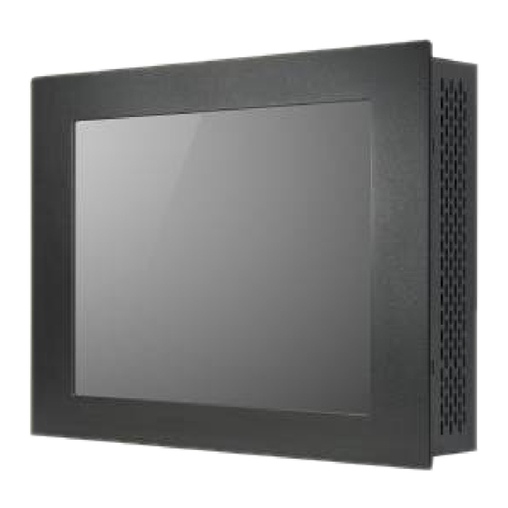
1.5 Brief Description of the APC-3X17B The APC-3517B/3717B/3917B is a high performance, compact and panel-mount industrial PC, which comes with a 15-inch (luminance of 300 cd/m²)/17-inch (luminance of 350 cd/m²)/19-inch (luminance of 300 cd/m²) TFT LCD. It is powered by an Intel Socket P Core 2 Duo Processor, up to Intel P8600 2.4GHz processor. -
Page 16: Panel Mounting
Figure 1.6. Just carefully place the unit through the hole and tighten the given 10 screws from the rear to secure the mounting. Figure 1.6: Panel mounting of the APC-3517B/3717B/3917B Figure 1.7: VESA mounting of the APC-3517B/3717B/3917B APC-3X17B User Manual... -
Page 17: Chapter 2 Hardware
Chapter 2 Hardware 2.1 Motherboard Figure 2.1: Motherboard Dimensions APC-3X17B User Manual... -
Page 18: Installations
PCIE configuration. To satisfy the special needs of high-end customers, PC104+ port (capable of adjusting IO voltage) richer extension functions. The product is widely used in various sectors of industrial control. 2.2.1 Jumpers Setting and Connectors Figure 2.2: Jumpers and Connectors Location_ Board Top APC-3X17B User Manual... - Page 19 Figure 2.3: Jumpers and Connectors Location_ Board Bottom APC-3X17B User Manual...
- Page 20 3. BAT1 : (1.25mm Pitch 1X2 box Pin Header) 3.0V Li battery is embedded to provide power for CMOS. Pin# Signal Name VBAT Ground 4. DCIN: (5.08mm Pitch 1x3 Pin Connector),DC9V ~ DC32V System power input connector. APC-3X17B User Manual...
- Page 21 6. ATX (option): (2.0mm Pitch 1X3 box Pin Header), connect PSON and 5VSB and Ground ignal, support ATX Power model. Reserved. Pin# Signal Name ATX PSON ATX Ground ATX 5VSB 7. CPU1: (Socket P), installing the CPU Socket. APC-3X17B User Manual...
- Page 22 Top of the board and supports 204Pin 1.5V DDRIII 800/1066MHz FSB SO-DIMM memory module up to 8GB. 10. CRT1: (CRT DB15 Connector ),Video Graphic Array Port, provide high-quality video output. they can not work at the same time for CRT1 and VGA1. APC-3X17B User Manual...
- Page 23 Pin6 is backlight control signal, support DC or PWM mode, mode select at BIOS CMOS menu. 13. LVDS1: (1.25mm Pitch 2x20 Connector), For 18/24-bit LVDS output connector, Fully supported by Intel GM45 chipset, the interface features dual channel 18/24-bit output. APC-3X17B User Manual...
- Page 24 & shutdown or awaken the system from sleep state. 16. JCOM1: (2.0mm Pitch 2x3 Pin Header), COM1 jumper setting, pin 1~6 are used to select signal out of pin 9 of COM1 port. APC-3X17B User Manual...
- Page 25 (Type DB9),Rear serial port, standard DB9 Male serial port is provided to make a direct connection to serial devices. Pin# Signal Name DCD# (Data Carrier Detect) RXD (Received Data) TXD (Transmit Data) DTR (Data Terminal Ready) Ground APC-3X17B User Manual...
- Page 26 They can be used directly via COM cable connection. COM6 port is controlled by pins No.1~3 of JCOM6,select output Signal 5V or 12v, For details, please refer to description of JCOM6. Signal Name Pin# Pin# Signal Name Ground JCOM6 select Setting APC-3X17B User Manual...
- Page 27 Line In is used for the connection of external audio source via a Line in cable. MIC is the port for microphone input audio. Signal Name Pin# Pin# Signal Name FRONT_OUTP-L FRONT_OUTP_R FRONT_OUTN_L FRONT_OUTN_R APC-3X17B User Manual...
- Page 28 (4x10 Pin), PCIe bus connector, it conforms to standard PCI Express x1 specification. Can expand support PCIe devices. ASB-M801T/ET:PCIEX2 connector in the top. ASB-M801B/EB:PCIEX2 connector in the Bottom. MODEL PC104+ / PCIEX2 ASB-M801T ASB-M801ET ASB-M801B Bottom ASB-M801EB Bottom APC-3X17B User Manual...
- Page 29 485- / 422TX- COM3 RS422 or Ground RS485 5V_S5 DCD4- RXD4 TXD4 DTR4- COM4 COM4 Ground DSR4- RTS4- CTS4- RI4- 5V_S5 5V_USB_9 5V_USB_1011 USB9_N USB10_N USB9 USB10 USB9_P USB10_P Ground Ground Ground Ground 5V_USB_1011 PWR_LED+ Power USB11_N PWR_LED- APC-3X17B User Manual...
- Page 30 Pin2-4: POWER LED, They are used to connect power LED. When the system is powered on or under S0/S1 state, the LED is normally on, when the system is under S4/S5 state, the LED is off. Pin5-7: RESET Button, They are used to connect reset button. The two pins are APC-3X17B User Manual...
- Page 31 Make sure that the connector pins have a one-to-one correspondence with chassis wiring, or it may cause boot up failure. 34. JCF/JSATA: (2.0mm Pitch 3x4 Pin Header), it provides selectable IDE_CF1 or SATA4 signal output control. Function Jumper setting SATA4 (Default) APC-3X17B User Manual...
- Page 32 Type I and Type II Compact Flash card. The operating voltage of CF card can be set as 3.3V or 5V, The default setting of the product is 3.3V. Please refer to description of JCF/JSATA Jumper setting. APC-3X17B User Manual...
- Page 33 The two pins are disconnected under normal condition. You may short them temporarily to realize system startup & shutdown or awaken the system from sleep state. PWR LED: POWER LED status. COM3: (Type DB9), I/O serial port, it provides selectable RS422/RS485 serial signal output. APC-3X17B User Manual...
- Page 34 Pin# Signal Name DCD# (Data Carrier Detect) RXD (Received Data) TXD (Transmit Data) DTR (Data Terminal Ready) Ground DSR (Data Set Ready) RTS (Request To Send) CTS (Clear To Send) RI (Ring Indicator) APC-3X17B User Manual...
- Page 35 Type II Compact Flash card. The operating voltage of CF card can be set as 3.3V or 5V. The default setting of the product is 3.3V. 42. TB-520P1: TB-520P1 connect to ASB-M801T/ET PC104+ connector, PC104+ is located at the top, It provides one PCI slot. APC-3X17B User Manual...
-
Page 36: Bios Setup
Press F11 to load default values and continue 0085 Press F11 key to enter Boot Menu during POST, as shown by the following figure. Please select boot device: Network: IBA GE Slot 0200 v1353 Network: IBA GE Slot 0300 v1353 APC-3X17B User Manual... -
Page 37: Bios Setup Utility
BIOS SETUP UTILITY Main Advanced PCIPnP Boot Security Chipset Exit System Overview User [ENTER],[TAB] AMIBIOS or [SHIFT-TAB] to Version : 08.00.15 Select a field Build Date : 05/13/11 Use[+] or [-] to : M801V001 configure system Time. Processor APC-3X17B User Manual... -
Page 38: Advanced Settings
Exit Advanced Settings Configure CPU WARNING: Setting wrong values In below sections may cause system to malfunction. ► CPU Configuration ► IDE Configuration ► Super IO Configuration ► Hardware Health Configuration ► ACPI Configuration ► AHCI Configuration APC-3X17B User Manual... - Page 39 Max CPUID Value Limit [Disabled] ↑↓ Select Item Execute-Disable Bit Capability [Enabled] +- Charge Field Intel(R) C-SATAE tech [Disabled] F1 General Help F10 Save and Exit ESC Exit V02.61 © Copyright 1985-2006 American Mega trends , Inc. APC-3X17B User Manual...
- Page 40 SATA#1 Configuration [Enhanced] ► Primary IDE Master : [Not Detected] ► Primary IDE Slaver : [Not Detected] ► Secondary IDE Master : [Not Detected] ← Select Screen ► Secondary IDE Slaver : [Not ↑↓ Select Item Detected] APC-3X17B User Manual...
- Page 41 V02.61 © Copyright 1985-2006 American Mega trends , Inc. SATA#1 Configuration: [Compatible] [Disabled] [Enhanced] Configure SATA as: [IDE] [RAID] [AHCI] SATA#2 Configuration: [Enhanced] [Disabled] Hard Disk Write Protect: [Disabled] [Enabled] IDE Detect Time Out : [35] [10] [15] [20] APC-3X17B User Manual...
- Page 42 F1 General Help F10 Save and Exit ESC Exit V02.61 © Copyright 1985-2006 American Mega trends , Inc. Serial Port3 Mode: COM3 Options: [RS485 ] [RS422] [RS422] for RS422 Mode [RS485] for RS485 Mode 3.4.4 Hardware Health Configuration APC-3X17B User Manual...
- Page 43 V02.61 © Copyright 1985-2006 American Mega trends , Inc. System Temperature: Show you the current system temperature. CPU Temperature: Show you the current CPU temperature. CPUFAN Speed: Show you the current CPU Fan operating speed. Maximum CPU Temperature: [60℃/140℉] [55℃/131℉] [65℃/149℉] [70℃/158℉] APC-3X17B User Manual...
- Page 44 [Disabled] AMI OEMB table: [Enabled] [Disabled] Headless mode: [Disabled] [Enabled] [Chipset ACPI Configuration]: APIC ACPI SCI IRQ: [Disabled] [Enabled] High Performance Event Timer: [Disabled] [Enabled] 3.4.6 AHCI Configuration BIOS SETUP UTILITY Advanced AHCI Setting Enables For supporting APC-3X17B User Manual...
- Page 45 Select MPS MPS Revision [1.1] Revision ← Select Screen ↑↓ Select Item +- Charge Field F1 General Help F10 Save and Exit ECS Exit V02.61 © Copyright 1985-2006 American Mega trends , Inc. MPS Revision: [1.1] [1.4] APC-3X17B User Manual...
- Page 46 V02.61 © Copyright 1985-2006 American Mega trends , Inc. Active State Power Management: [Disabled] [Enabled] 3.4.9 Smbios Configuration BIOS SETUP UTILITY Advanced Smbios Configuration SMBIOS SMI Wrapper Smbios Smi Support [Enabled] Support for PnP Func 50h-54h ← Select Screen ↑↓ Select Item APC-3X17B User Manual...
- Page 47 BIOS EHCI Hand-Off [Enabled] Select Screen ↑↓ Select Item Charge Field General Help F10 Save and Exit ESC Exit V02.61 © Copyright 1985-2006 American Mega trends , Inc. Legacy USB Support: [Enabled] [Disabled] USB2.0 Controller Mode: [FullSpeed] [HiSpeed] APC-3X17B User Manual...
-
Page 48: Advanced Pci/Pnp Settings
PCI IDE BusMaster [Disabled] OffBoard PCI/ISA IDE Card [Auto] ← Select Screen IRQ3 ↑↓ Select Item [Available] +- Charge Field IRQ4 F1 General Help [Available] F10 Save and Exit IRQ5 ESC Exit [Available] IRQ7 [Available] IRQ9 [Available] APC-3X17B User Manual... - Page 49 [224] [248] Allocate IRQ to PCI VGA: [Yes] [No] Palette Snooping: [Disabled] [Enabled] PCI IDE BusMaster: [Disabled] [Enabled] OffBoard PCI/ISA IDE Card: Some PCI IDE cards may require this to be set to the PCI slot number APC-3X17B User Manual...
-
Page 50: Boot Settings
Size of memory block to reserve for legacy ISA devices. [Disabled] [16k] [32k] [64k] 3.6 Boot Settings BIOS SETUP UTILITY Main Advanced PCIPnP Boot Security Chipset Exit Boot Settings Configure Settings During System Boot ► Boot Setting Configuration ► Boot Device Priority ► Hard Disk Drives APC-3X17B User Manual... - Page 51 [Enabled] Disabled: Displays normal POST messages. Enabled: Displays OEM logo instead of POST messages. AddOn ROM Display Mode: Set display mode for Option ROM. [Force BIOS] [Keep Current] Bootup Num-Lock: Select Power-on state for Numlock. [On] [Off] APC-3X17B User Manual...
-
Page 52: Security Settings
3.7 Security Settings BIOS SETUP UTILITY Main Advanced PCIPnP Boot Security Chipset Exit Security Settings Install or Change the Supervisor Password :Not Installed password. User Password :Not Installed Change Supervisor Password Change User Password Boot Sector Virus Protection [Disabled] APC-3X17B User Manual... - Page 53 Once the password feature is used, you will be requested to type the password each time you enter BIOS setup. This will prevent unauthorized persons from changing your system configurations. Also, the feature is capable of requesting users to enter the password prior to system APC-3X17B User Manual...
-
Page 54: Advanced Chipset Settings
Due to limited address length of BIOS, only a portion of panel parameters are listed in BIOS Setup. If the connected panel is not included in the parameter list, display problem will occur. In this case, Please do not change BIOS setup. 3.8.1 North Bridge Configuration APC-3X17B User Manual... - Page 55 V02.61 © Copyright 1985-2006 American Mega trends , Inc. Memory Remap Feature: [Enabled] [Disabled] Memory Hole: [Disabled] [15MB-16MB] Initate Graphic Adapter: Select which graphics controller to use as the primary boot device. [PCI/IGD] [IGD] IGD Graphics Mode Select: [Enabled, 64MB] APC-3X17B User Manual...
- Page 56 Backlight Control Mode [DC] F10 Save and Exit Backlight Image Adaptation ESC Exit [VBIOS-Default] V02.61 © Copyright 1985-2006 American Mega trends , Inc. DVMT Mode Select: [DVMT Mode] [FIXED Mode] DVMT/FIXED Memory Size: [256MB] [128MB] [Maximum DVMT] APC-3X17B User Manual...
- Page 57 [1280x1024 24bit 2ch] [1440x900 24bit 2ch] [1600x900 24bit 2ch] [1680x1050 24bit 2ch] [1920x1080 24bit 2ch] Backlight Control Support [VBIOS-Default] [Both BLC & BIA Disabled] [BLC Enabled] Backlight Control Control: [Level8] [Level0] [Level1] [Level2] [Level3] [Level4] [Level6] [Level7] [Level9] [Level10] APC-3X17B User Manual...
- Page 58 USB2.0 Controller [Enabled] 6 USB Ports Keep USB Power at S5 [Enabled] 8 USB Ports Wireless Controller [Enabled] 10 USB Ports HAD Controller [Enabled] 12 USB Ports SMBUS Controller [Enabled] SLP_S4# Min. Assertion Width [4 to 5 Seconds] APC-3X17B User Manual...
- Page 59 [2 USB Ports] [4 USB Ports] [6 USB Ports] [8 USB Ports] [10 USB Ports] USB 2.0 Controller: [Enabled] Keep USB Power at S5: [Enabled] [Disabled] Wireless Controller [Enabled] [Disabled] HDA Controller: [Enabled] [Disabled] SMBUS Controller: [Enabled] [Disabled] APC-3X17B User Manual...
- Page 60 PCIE Ports Configuration: PCIE Port 0: [Auto] [Enabled] [Disabled] PCIE Port 1: [Auto] [Enabled] [Disabled] PCIE Port 2: [Auto] [Enabled] [Disabled] PCIE Port 3: [Auto] [Enabled] [Disabled] PCIE Port 4: [Auto] [Enabled] [Disabled] PCIE High priority Port: [Disabled] APC-3X17B User Manual...
-
Page 61: Exit Options
Exit Exit Options Exit system setup Save Changes and Exit after saving the Discard Changes and Exit changes Discard Changes F10 key can be used For this operation Load Optimal Defaults Load Failsafe Defaults ← Select Screen APC-3X17B User Manual... - Page 62 F7 key can be used for this operation) [OK] [Cancel] Load Optimal Defaults: Load Optimal Defaults? F9 key can be used for this operation) [OK] [Cancel] Load FailSafe Defaults: Load FailSafe Defaults? F9 key can be used for this operation) [OK] [Cancel] APC-3X17B User Manual...
-
Page 63: Chapter 4 Installation Of Drivers
Intel chipset driver VGA driver LAN drivers Audio driver .NET framework 3.5 driver Installation instructions are given below. Important Note: After installing your Windows operating system, you must install first the Intel Chipset Software Installation Utility before proceeding with the installation of drivers. APC-3X17B User Manual... -
Page 64: Intel Chipset Driver
4.1 Intel Chipset Driver To install the Intel chipset driver, please follow the steps below. Step 1: Select Chipset from the list Follow the step-by-step installation process to install the driver. APC-3X17B User Manual... - Page 65 APC-3X17B User Manual...
- Page 66 Click Finish, when the installation process is complete, the Setup Complete screen appears. See as picture. APC-3X17B User Manual...
-
Page 67: Intel Graphics Media Accelerator Driver
4.2 Intel Graphics Media Accelerator driver To install the VGA drivers, follow the steps below to proceed with the installation. Step 1: Click Intel(R) GM45 Chipset Family Graphics Driver. Follow the step-by-step installation process to install the Graphics Media Accelerator driver. APC-3X17B User Manual... - Page 68 APC-3X17B User Manual...
- Page 69 APC-3X17B User Manual...
- Page 70 Click FINISH; A Driver Installation Complete. APC-3X17B User Manual...
-
Page 71: Intel 82574L Lan Device Driver
4.3 Intel 82574L LAN Device Driver To install the Intel R 82574L Gigabit LAN connect device driver, please follow the steps below. Select LAN from the list Follow the step-by-step installation process to install the LAN driver. APC-3X17B User Manual... - Page 72 APC-3X17B User Manual...
- Page 73 Click FINISH; A Driver Installation Complete. APC-3X17B User Manual...
-
Page 74: Realtek Alc662 Hd Audio Driver Installation
4.4 Realtek ALC662 HD Audio Driver Installation To install the Realtek High Definition (HD) Audio driver, please follow the steps below. Select Audio from the list Follow the step-by-step installation process to install the Realtek HD Audio driver. APC-3X17B User Manual... - Page 75 Click FINISH; A Driver Installation Complete. APC-3X17B User Manual...
-
Page 76: Microsoft .Net Framework 3.5 Service Installation
4.5 Microsoft .NET Framework 3.5 Service Installation To install the Microsoft .NET Framework 3.5 Service, please follow the steps below. APC-3X17B User Manual... - Page 77 APC-3X17B User Manual...
- Page 78 APC-3X17B User Manual...
-
Page 79: Chapter 5 Touch Screen Installation
Before installing the Windows 2000/XP driver software, you must have the Windows 2000/XP system installed and running on your computer. You must also have one of the following PenMount 6000 series controller or control boards installed: PM6500, PM6300. APC-3X17B User Manual... -
Page 80: Installing Software
When the system first detects the controller board, a screen appears that shows “Unknown Device”. Do not use this hardware wizard. Press Cancel. 2. Insert the product CD install setup.exe. the screen below would appear. Click touch panel driver APC-3X17B User Manual... - Page 81 3. A License Agreement appears. Click “I accept…” and “Next” APC-3X17B User Manual...
- Page 82 4. Ready to Install the Program. Click “Install” 5. Installing APC-3X17B User Manual...
- Page 83 6. The “Install Shield Wizard Completed” appears. Click “Finish”. APC-3X17B User Manual...
-
Page 84: Software Functions
‘Advanced Calibration’ adjusts aging touch screens. Standard Calibration Click this button and arrows appear pointing to red squares. Use your finger or stylus to touch the red squares in sequence. After the fifth red point calibration is complete. To skip, press ‘ESC’. APC-3X17B User Manual... - Page 85 ($) 0= Standard Calibration 4=Advanced Calibration 4 9=Advanced Calibration 9 16=Advanced Calibration 16 25=Advanced Calibration 25 1. Please select a device then click “Configure”. You can also double click the device too. 2.Click “Standard Calibration” to start calibration procedure APC-3X17B User Manual...
- Page 86 NOTE: The older the touch screen, the more Advanced Mode calibration points you need for an accurate calibration. Use a stylus during Advanced Calibration for greater accuracy. Please follow the step as below: 3. Come back to “PenMount Control Panel” and select “Tools” then Click “Advanced Calibration”. APC-3X17B User Manual...
- Page 87 Select “Device” to calibrate, then you can start to do “Advanced Calibration”. NOTE: Recommend to use a stylus during Advanced Calibration for greater accuracy. APC-3X17B User Manual...
- Page 88 Setting APC-3X17B User Manual...
- Page 89 About This panel displays information about the PenMount controller and driver version. APC-3X17B User Manual...
- Page 90 Rotating function is disabled. Enable the multiple display function as follows: 1. Check the “Multiple Monitor Support” box; then click “Map Touch Screens” to assign touch controllers to displays. 2. When the mapping screen message appears, click “OK” APC-3X17B User Manual...
- Page 91 3. If you change the resolution of display or screen address, you have to redo Map Touch Screens so the system understands where the displays are. 4. If you more monitor mapping one touch screen, Please press ‘S’ to skip mapping step. APC-3X17B User Manual...
- Page 92 Enable Advanced Calibration function Right Button Icon Enable right button function. The icon can show on Desktop or System Tray (menu bar). About You can see how many devices of PenMount controller that are plugged to your system APC-3X17B User Manual...
- Page 93 PenMount Monitor Menu Icon The PenMount monitor icon (PM) appears in the menu bar of Windows 2000/XP system when you turn on PenMount Monitor in PenMount Utilities. PenMount Monitor has the following function APC-3X17B User Manual...
- Page 94 2. Choose the rotate function (0°, 90°, 180°, 270°) in the 3rd party software. The calibration screen appears automatically. Touch this point and rotation is mapped. NOTE: The Rotate function is disabled if you use Monitor Mapping APC-3X17B User Manual...
Need help?
Do you have a question about the APC-3X17B and is the answer not in the manual?
Questions and answers