Table of Contents
Advertisement
Quick Links
APC-3XX2
TM
7" and 8" Fanless Total IP66 Intel Atom
E3845 Fleet Management Panel PC
User Manual
Release Date
Revision
Dec. 2016
V1.2
®2016 Aplex Technology, Inc.
All Rights Reserved.
Published in Taiwan
Aplex Technology, Inc.
15F-1, No.186, Jian Yi Road, Zhonghe District, New Taipei City 235, Taiwan
Tel: 886-2-82262881 Fax: 886-2-82262883 URL:
www.aplextec.com
APC-3XX2 User Manual
0
Advertisement
Table of Contents

Related Manuals for Aplex APC-3XX2 series


Summary of Contents for Aplex APC-3XX2 series
- Page 1 E3845 Fleet Management Panel PC User Manual Release Date Revision Dec. 2016 V1.2 ®2016 Aplex Technology, Inc. All Rights Reserved. Published in Taiwan Aplex Technology, Inc. 15F-1, No.186, Jian Yi Road, Zhonghe District, New Taipei City 235, Taiwan Tel: 886-2-82262881 Fax: 886-2-82262883 URL: www.aplextec.com...
-
Page 2: Revision History
Revision History Reversion Date Description 2016/08/24 Official Version 2016/09/10 Modify PB-422B Specifications 2016/12/05 Add 7” Panel PC: APC-3072, and add projected capacitive touch APC-3XX2 User Manual... -
Page 3: Warning!/Caution/Disclaimer
This information in this document is subject to change without notice. In no event shall Aplex Technology Inc. be liable for damages of any kind, whether incidental or consequential, arising from either the use or misuse of information in this document or in any related materials. -
Page 4: Packing List/Safety Precautions
Packing List Accessories (as ticked) included in this package are: □ Adaptor □ Driver & manual CD disc □ Other.___________________(please specify) Safety Precautions Follow the messages below to prevent your systems from damage: ◆ Avoid your system from static electricity on all occasions. ◆... -
Page 5: Table Of Contents
Table of Contents Revision History…………………………………………………………………………………………….1 Warning!/Caution/Disclaimer........…………………………….……..….2 Packing List/Safety Precautions..………………………………………………………………..3 Chapter 1 Getting Started 1.1 Features……………….……………………………………...………………………………….6 1.2 Specifications…………………………………………………………………………………...6 1.3 Dimensions…………………………………..………………………...…………………..9 1.4 Brief Description of APC-3XX2..………………………………………………..……11 1.5 Installation of SD Card and SIM Card……………………………………………….14 1.6 The Mounting of Stand I………………………………………………………………….15 1.7 The Mounting of Stand II…………………………………………………………………16 1.8 VESA Mounting……………………………………………………………………………….17 1.9 Panel Mounting………….…………………………………………………………………..17 Chapter 2... - Page 6 Chapter 5 Installation of Drivers 5.1 Intel(R) AtomTM SoC Chipset Driver…..………………………………………….52 5.2 Intel(R) VGA Chipsrt Driver..............55 5.3 Intel(R) 82574L LAN Driver…………............59 5.4 Rearltek ALC662 HD Audio Driver............62 5.5 USB 3.0 Driver………………….……………………………………………………………..63 5.6 Com Driver…..................66 Chapter 6 Touch Screen Installation 6.1 Windows 7/8.1 Universal Driver Installation for PenMount 6000 Series…………………………………………….…………………………………………..……69 6.2 Software Functions……………………………..……….………………………….……78 Figures...
-
Page 7: Getting Started
Chapter 1 Getting Started 1.1 Features Fleet management panel PC High brightness LED backlight LCD Intel® Atom Processor E3845 4GB DDR3L memory on board Wide range 6~36V DC power input Total 6 sides IP66 ... - Page 8 Serial/Parallel 1 x M12 for RS-232/422/485, default RS-232 1 x M12 for RS-232 COM1/2: Pin Define 1 x M12 for LAN LAN: Pin Define LAN1_0+ LAN1_0- LAN1_1+ LAN1_1- LAN1_2+ LAN1_2- LAN1_3+ LAN1_3- Power 1 x DC power input (6~36V) by M12 connector Others 1 x SMA connector for option GPS antenna Expansion Slots...
- Page 9 Contrast Ratio 500: 1 500: 1 Luminance (cd/m2) (option 1000nits) (option 1000nits) Viewing Angle 135(H) / 125(V) 140(H) / 125(V) Backlight Lifetime 50,000 hrs 50,000 hrs Touch Screen – Resistive Touch Window Type (Default for APC-3082; Option for APC-3072) Interface Light Transmission Over 80% Touch Screen –...
-
Page 10: Dimensions
1.3 Dimensions Figure 1.1: Dimensions of APC-3072 Figure 1.2: Dimensions of APC-3072 with Stand APC-3XX2 User Manual... -
Page 11: Figure 1.3: Dimensions Of Apc-3082
Figure 1.3: Dimensions of APC-3082 Figure 1.4: Dimensions of APC-3082 with Stand APC-3XX2 User Manual... -
Page 12: Brief Description Of Apc-3Xx2
1.4 Brief Description of APC-3XX2 APC-3XX2 is a fanless and fleet management low power consumption designed panel PC. It comes with total 6 sides IP66 waterproof grade, powered by Intel Atom E3845 processor, and supports 4GB DDR3L memory onboard. The LCD supports LED backlight for power saving, and can be optional high brightness LCD for sunlight readable. -
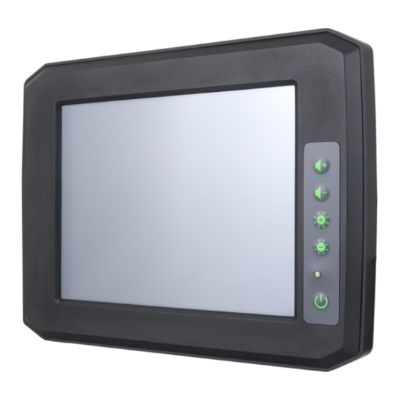
Page 13: Figure 1.7 Front View Of Apc-3082
Figure 1.7 Front View of APC-3082 Figure 1.8 Rear View of APC-3082 APC-3XX2 User Manual... -
Page 14: Figure 1.9 Apc-3072 With Stand
Figure 1.9 APC-3072 with Stand Figure 1.10 APC-3082 with Stand APC-3XX2 User Manual... -
Page 15: Installation Of Sd Card And Sim Card
1.5 Installation of SD Card and SIM Card Step 1 There are two screws to deal with when enclosing or removing the chassis. Gently remove two screws. Step 2 Take off the chassis cover. You can replace the SIM card as shown in the picture. -
Page 16: The Mounting Of Stand I
Stand I 1.6 The Mounting of Step 1 Put the stand on the panel PC. Step 2 Screw the two screws at one side. Step 3 Screw the two screws at the other side. Step 4 This is how it looks when the stand is mounted. -
Page 17: The Mounting Of Stand Ii
1.7 The Mounting of Stand II Step 1 Put the stand on the panel PC. Step 2 Screw the screw at one side Step 3 Screw the screw at another side. Step 4 Screw the screw at another side. APC-3XX2 User Manual... -
Page 18: Vesa Mounting
Step 5 Screw the last screw as shown in the picture. After screwing the four screws, you manage to mount the stand. 1.8 VESA Mounting APC-3XX2 is designed to be VESA mounted as shown in the Figure 1.11. Just carefully place the unit through the hole and tighten the given screws from the rear to secure the mounting. -
Page 19: Chapter 2 Osd
Chapter 2 2.1 APC-3072 Front Function Keyboard with Power Button Default General Keyboard F1~F6 key, programmable other define. 2.2 APC-3082 OSD Functions and Control Volume Up: To adjust the volume up. Volume Down: To adjust the volume down. Brightness Up: To adjust the brightness up. Brightness Down: To adjust the brightness down. -
Page 20: Chapter 3 Motherboard
Chapter 3 Motherboard 3.1 Motherboard Introduction SBC-7810 is a 146 x 80mm Industrial motherboard developed on the basis of Intel Bay trail-I/M Processors, which provides abundant peripheral interfaces to meet the needs of different customers. Also, it features dual GbE ports, 4-COM ports and two Mini PCIE configuration, one CRT port, one LVDS interface. - Page 21 USB 2.0 HUB (USB2514): 2 x USB 2.0 Pin header for MIO1 (E-USB5/E-USB6) 1 x USB 2.0 for MPCIE1 (E-USB7) 1 x USB 2.0 for MPCIE2 (E-USB8) 1 x RS232/RS422/RS485 header for CN1(COM1) Pin 16 w/5V/12V/RI select Serial 1 x RS232/RS422/RS485 header for MIO1(COM2) Pin 16 w/5V/12V/RI select 2 x UART header for CN4 (F81216AD/COM3/COM4) Digital I/O...
-
Page 22: Figure 3.1: Motherboard Dimensions
Figure 3.1: Motherboard Dimensions APC-3XX2 User Manual... -
Page 23: Jumpers And Connectors Location
3.3 Jumpers and Connectors Location Figure 3.2: Jumpers and Connectors Location- Board Top Figure 3.3: Jumpers and Connectors Location- Board Bottom APC-3XX2 User Manual... -
Page 24: Jumpers Setting And Connectors
3.4 Jumpers Setting and Connectors 1. U2: (FCBGA1170), onboard Intel Bay trail-I/M Processors. Model Processor Number Cores/Threads Remarks SBC-7810-E3845-4G E3845 1.91GHz 4 / 4 SBC-7810-N2930-2G N2930 1.83 up to 4 / 4 4.5/7.5W option 2.16GHz 2. U3/U4/U5/U6: (FBGA96)Onboard DDR3L Memory. Model Memory SBC-7810-E3845-4G... - Page 25 (2.0mm Pitch 1x6 wafer Pin Header), Backlight control connector for LVDS. Pin# Power Input +DC12V +DC12V Ground Ground BKLT_EN_OUT BKLT_CTRL 7. JP6: (2.0mm Pitch 2x2 Pin Header),LVDS jumper setting. Function (CN1) Pin1-Pin2 (Close) Single channel LVDS (Default) Pn1-Pin2 (Open) Dual channel LVDS Pin3-Pin4 (Close) 8/24 bit Pin3-Pin4 (Open)
- Page 26 Ground Ground LA_D0_P LA_D0_N LA_D1_P LA_D1_N LVDS LVDS LA_D2_P LA_D2_N LA_D3_P LA_D3_N LA_CLKP LA_CLKN LB_D0_P LB_D0_N LB_D1_P LB_D1_N LB_D2_P LB_D2_N LB_D3_P LB_D3_N LB_CLKP LB_CLKN Ground Ground USB2 USB2 USB2_P USB2_N 5V_S5_USB 5V_S5_USB Power LED PWR_LED+ Ground Power LED ( ) 9.
- Page 27 Function Signal Name Pin# Signal Name Function Ground PWRBTN_ON- Ground EC_SMDATA1 EC_SMCLK1 Ground Ground FP_TXD1 FP_RXD1 12V_S0 12V_S0 12. CN1: (DF13-30P-1.25mm Connector), For expand output connector, It provides one CRT, one USB2.0,one RS232 or RS422 or RS485. connected to the TB-535 I/O board. Function Signal Name Pin#...
- Page 28 13. JP1: (2.0mm Pitch 2x3 Pin Header), COM1 jumper setting, pin 1~6 are used to select signal out of pin 16 of COM1 port. JP1 Pin# Function Close 1-2 COM1 RI (Ring Indicator) (default) Close 3-4 COM1 Pin16: DC+5V (option) Close 5-6 COM1 Pin16: DC+12V (option)
- Page 29 (UART) COM3_RXD COM4_RXD (UART) COM3_TXD COM4_TXD COM3_DCD- COM4_DCD- COM3_RI- COM4_RI Ground Ground 16. MIO1: (DF13-40P-1.25mm Connector),For expand output connector, It provides eight GPIO, one RS232 or RS422 or RS485, two USB2.0,one PS/2 mouse, one PS/2 key board, one HDD LED. Function Signal Name Pin#...
- Page 30 JP1 Pin# Function Close 1-2 COM2 RI (Ring Indicator) (default) Close 3-4 COM2 Pin16: DC+5V (option) Close 5-6 COM2 Pin16: DC+12V (option) 18. MSATA1: (50.95mmx30mm Socket 52Pin), mSATA socket, it is located at the top, it supports SATAII Signal and SMBUS and B2 mSATA bus for flash disk signal.
- Page 31 Signal Name Pin# Signal Name GND_AUD LINE-OUT-L LINE-OUT-R FRONT_JD MIC-IN-L MIC-IN-R GND_AUD MIC1_JD 27. SPK1: (2.0mm Pitch 1x4 Wafer Pin Header),support 2-W(per channel) efficient, audio power amplifier for driving bridged-tied stereo speakers. Pin# Signal Name SPK_OUTR_P SPK_OUTR_N SPK_OUTL_N SPK_OUTL_P 28. BUZ1: Onboard buzzer.
- Page 32 CN1: Function Signal Name Pin# Signal Name Function 5V_USB3 5V_USB3 USB1 USB1_N (NC) (USB2.0) USB1_P Ground Ground CRT_DDCDATA CRT_DDCCLK Ground 5V_VGA COM1:RI/5V/12V VCC_RI1- CRT_H_SYNC COM1:232/422 DTR1-_422RX CRT_V_SYNC COM1:232 CTS1- 3P3V_S0 COM1:232/422 TXD1_422RX+ CRT_FB_RED COM1:232 RTS1- Ground COM1:232/422/485 RXD1_422TX+_485+ CRT_FB_GREEN COM1:232 DSR1- CRT_FB_BLUE COM1:232/422/485...
- Page 33 LAN1_100M_LINK- LAN2_100M_LINK LAN1_ACT- LAN2_ACT MIO1/USB5 USB2_P USB2_N MIO1/USB5 Power on/off WRBTN_ON- Ground USB12: (Double stack USB typeA), USB connector, it provides up to two USB2.0 ports, support USB full-speed and low-speed signaling. Each USB Type A Receptacle (2 Ports) Current limited value is 1.5A. If the external USB device current exceeds 1.5A, please separate connectors into different Receptacle.
- Page 34 RS232 (Default) Pin# Signal Name DCD# (Data Carrier Detect) RXD (Received Data) TXD (Transmit Data) DTR (Data Terminal Ready) Ground DSR (Data Set Ready) RTS (Request To Send) CTS (Clear To Send) JP1 select Setting (RI/5V/12V) BIOS Setup: Advanced/F81216SEC Super IO Configuration/Serial Port 1 Configuration【RS-232】...
-
Page 35: Power Board Pb-422B Jumpers Setting And Connectors
Ground BIOS Setup: Advanced/F81216SEC Super IO Configuration/Serial Port 1 Configuration【RS-485】 PS_ON: Power on/off button, They are used to connect power switch button. 3.5 Power Board PB-422B Jumpers Setting and Connectors PB422B is a power management board for SBC-7810. It contains DC_IN1、DC_OUT1、 SW_C1、SW_T1、FP1 and BAT1 connectors. - Page 36 RSV_SW_P3_3 PWRON_TST- 4. SW_T1: 6 bit dial switch. SW_T1 provides the delay signal. Signal Name Pin# Signal Name SET_ON_1 SET_ON_2 SET_ON_3 SET_OFF_1 SET_OFF_2 SET_OFF_3 5. FP1: (1.25mm Pitch 2*10 Pin Connector). FP1 communicates with SBC-7810 through IIC and UART and receive the power button signal. Signal Name Pin# Signal Name...
-
Page 37: Chapter 4 Uefi Setup Utility
Chapter 4 UEFI SETUP UTILITY 4.1 Operations after POST Screen After CMOS discharge or BIOS flashing operation, Press [Delete] key to enter CMOS Setup. 4.2 BIOS Setup Utility Press [Delete] key to enter BIOS Setup utility during POST, and then a main menu containing system summary information will appear. -
Page 38: Main Settings
4.3 Main Settings System Time: Set the system time, the time format is: Hour: 0 to 23 Minute: 0 to 59 Second: 0 to 59 System Date: Set the system date, the date format is: Day: Note that the ‘Day’ automatically changes when you set the date APC-3XX2 User Manual... -
Page 39: Advanced Settings
Month: 01 to 12 Date: 01 to 31 Year: 1999 to 2099 4.4 Advanced Settings 4.4.1 ACPI Settings Enable ACPI Auto Conf: [Disabled] [Enabled] Enable Hibernation: [Enabled] [Disabled] ACPI Sleep State: [S3 (Suspend to RAM) ] [Suspend Disabled] Lock Legacy Resources: [Disabled] APC-3XX2 User Manual... - Page 40 [Enabled] 4.4.2 F81216SEC Super IO Configuration Super IO chip F81216SEC Serial Port 1 Configuration UART1 Mode Selection: [RS-232] [RS-485] [RS-422] Serial Port 2 Configuration Backlight PWM Controller: [RS-232] [RS-485] [RS-422] Serial Port 3 Configuration Change Settings [Auto] Serial Port 4 Configuration Change Settings [Auto] 4.4.3 IT8518 Super IO Configuration Super IO chip IT8518/IT8519...
- Page 41 L1 Date Cache 24KB x 4 L1 Code Cache 32KB x 4 L2 Cache 1024 KB x 2 L2 Cache Not Present CPU Thermal configuration CPU Speed 1918 MHz 64-bit Supported Limit CPUID Maximum: [Disabled] [Enabled] Execute Disable Bit: [Enabled] [Disabled] Intel Virtualization Technology: [Enabled]...
- Page 42 [Enabled] SATA Speed Support [Gen2] [Gen1] SATA ODD Port [No ODD] [Porto ODD] [Port1 ODD] [Disabled] SATA Mode [AHCI Mode] [IDE Mode] Serial-ATA Port 0 [Enabled] [Disabled] SATA Port0 Hotplug [Disabled] [Enabled] Serial-ATA Port 1 [Enabled] [Disabled] SATA Port1 Hotplug [Disabled] [Enabled] SATA Port0...
- Page 43 SCC SD Card Support [Enabled] SDR25 Support for SDCard [Enabled] SDR50 Support for SDCard [Enabled] MIPI HSI Support [Disabled] LPSS Configuration [Enabled] LPSS DMA #1 Support [Enabled] LPSS DMA #2 Support [Enabled] LPSS I2C #1 Support [Enabled] LPSS I2C #2 Support [Enabled] LPSS I2C #3 Support [Enabled]...
- Page 44 [Do not launch] [Legacy] Storage [UEFI] [Do not launch] [Legacy] Video [Legacy] [UEFI] [Do not launch] Other PCI devices [UEFI] [Do not launch] [Legacy] 4.4.14 SDIO Configuration 4.4.15 USB Configuration USB Configuration USB Module Version 8.11.02 USB Devices: 1 keyboard, 2 Mice,2 Hubs Legacy USB Support: [Enabled] [Disabled]...
-
Page 45: Chipset Settings
[20 sec] [10 sec] [30 sec] [40 sec] Device power-up delay [Auto] [Manual] 4.4.16 Platform Trust Technology Ftpm [Disabled] [Enabled] 4.4.17 Security Configuration 4.5 Chipset Settings 4.5.1 Host Bridge ►Intel IGD Configuration APC-3XX2 User Manual... - Page 46 ►IGD – LCD Control Force Lid Status [On] [off] [Auto] ALS Support [Disabled] IGD Flat Panel [Auto] Pannel Scaling [Auto] ►Memory Frequency and Timing ►Graphics Power Management Control Memory Information Total Memory 4096 MB(DDR3L) Memory Slot0 4096 MB(DDR3L) DIMM#2 Not Present Max TOLUD [Dynamic] [2GB]...
- Page 47 [Level 10] [Level 11] [Level 12] [Level 13] [Level 14] [Level 15] Power on Delay Time [10 Second] [30 Second] [1min] [5min] [10min] [15min] [30min] [1Hour] [1.5Hour] [2Hour] [2.5Hour] [3Hour] 4.5.2 South Bridge ►Azalia HD Audio ►USB Configuration USB OTG Support [Disabled] USB VBUS [on]...
-
Page 48: Security Settings
4.6 Security Settings 4.6.1 Administrator Password 4.6.2 User Password Type the password with up to 20 characters and then press Enter key. This will clear all previously typed CMOS passwords. You will be requested to confirm the password. Type the password again and press Enter key. -
Page 49: Boot Settings
Once the password feature is used, you will be requested to type the password each time you enter BIOS setup. This will prevent unauthorized persons from changing your system configurations. Also, the feature is capable of requesting users to enter the password prior to system boot to control unauthorized access to your computer. -
Page 50: Save & Exit Settings
Boot Option Priorities Boot Option #1 Sets the system boot order Hard Drive BBS Priorities [SATA PM:*** … ] Boot Option #1 SATA PM:***… ****** Disabled 4.8 Save & Exit Settings Save Changes and Exit Save & Exit Setup save Configuration and exit ? [Yes] [No] Discard Changes and Ext... - Page 51 [No] Save Changes and Reset Save & reset Save Configuration and reset? [Yes] [No] Discard Changes and Reset Reset Without Saving Reset without saving? [Yes] [No] Save Changes Save Setup Values Save configuration? [Yes] [No] Discard Changes Load Previous Values Load Previous Values? [Yes] [No] Restore Defaults...
-
Page 52: Chapter 5 Installation Of Drivers
Chapter 5 Installation of Drivers This chapter describes the installation procedures for software and drivers under the windows 7. The software and drivers are included with the motherboard. The contents include Intel chipset driver, VGA driver, LAN driver, Audio driver, USB 3.0 driver, and Com driver installation instructions are given below. -
Page 53: Intel(R) Atomtm Soc Chipset Driver
5.1 Intel(R) AtomTM SoC Chipset Driver To install the Intel chipset driver, please follow the steps below. Step 1. Select Intel AtomTM SoC Chipset from the list Step 2. Click Next to setup program. APC-3XX2 User Manual... - Page 54 Step 3. Read the license agreement. Click Yes to accept all of the terms of the license agreement. Step 4. Click Next to continue. APC-3XX2 User Manual...
- Page 55 Step 5. Click Next. Step 6. Select Yes, I want to restart this computer now. Click Finish, then remove any installation media from the drives. APC-3XX2 User Manual...
-
Page 56: Intel(R) Vga Chipsrt Driver
5.2 Intel(R) VGA Chipset Driver To install the VGA drivers, follow the steps below to proceed with the installation. Step 1.Select Intel(R) VGA Chipset Driver. Step 2. Click Automatically run WinSAT and enable the Windows Aero desktop theme(if supported). Click Next. APC-3XX2 User Manual... - Page 57 Step 3. Read license agreement. Click Yes. Step 4. Click Next to continue. APC-3XX2 User Manual...
- Page 58 Step 5. Click Install. Step 6. Click Install. APC-3XX2 User Manual...
- Page 59 Step 7. Click Next. Step 8. Select Yes, I want to restart this computer now. Then click Finish to complete the installation. APC-3XX2 User Manual...
-
Page 60: Intel(R) 82574L Lan Driver
5.3 Intel(R) 82574L LAN Driver To install the Intel(R) 82574L LAN Driver, please follow the steps below. Step 1. Select Intel(R) 82574L LAN Driver from the list. Step 2. Click Next to continue. APC-3XX2 User Manual... - Page 61 Step 3. Read license agreement. Click I accept the terms in the license agreement. Click Next. Step 4. Click Next to continue. APC-3XX2 User Manual...
- Page 62 Step 5. Click Install to begin the installation. Step 6. Click Finish to exit the wizard. APC-3XX2 User Manual...
-
Page 63: Rearltek Alc662 Hd Audio Driver
5.4 Realtek ALC662 HD Audio Driver To install the Realtek ALC662 HD Audio Driver, please follow the steps below. Step 1. Select Realtek ALC662 GD Audio Driver from the list Step 2. Click Next to continue. APC-3XX2 User Manual... -
Page 64: Usb 3.0 Driver
Step 3. Select Yes, I want to restart my computer now., and then click Finish to complete installation. 5.5 USB 3.0 Driver To install the USB 3.0 Driver, please follow the steps below. Step 1. Select USB 3.0 Driver from the list. APC-3XX2 User Manual... - Page 65 Step 2. Click Next to continue. Step 3. Read the license agreement and click Yes to continue. APC-3XX2 User Manual...
- Page 66 Step 4. Click Next to continue. Step 5. Click Next to continue APC-3XX2 User Manual...
-
Page 67: Com Driver
Step 6. Select Yes, I want to restart this computer now., and then click Finish to complete the installation. 5.6 Com Driver To install the Com Driver, please follow the steps below. Step 1. Select Com Driver from the list. APC-3XX2 User Manual... - Page 68 Step 2. Click Next to continue. Step 3. Click install to begin the installation. APC-3XX2 User Manual...
- Page 69 Step 4. Click Finish to complete the installation. APC-3XX2 User Manual...
-
Page 70: Chapter 6 Touch Screen Installation
Chapter 6 Touch Screen Installation This chapter describes how to install drivers and other software that will allow your touch screen work with different operating systems. 6.1 Windows 7/8.1 Universal Driver Installation for PenMount 6000 Series Before installing the Windows 7/8.1 driver software, you must have the Windows 7/8.1 system installed and running on your computer. - Page 71 Step 2. Click Next to continue. Step 3. Read the license agreement. Click I Agree to agree the license agreement. APC-3XX2 User Manual...
- Page 72 Step 4. Choose the folder in which to install PenMount Windows Universal Driver. Click Install to start the installation. Step 5. Click Yes to continue. APC-3XX2 User Manual...
- Page 73 Step 6. Click Finish to complete installation. 6.1.2 Installing Software (Projected Capacitive) Step 1. Insert the product CD, the screen below would appear. Click touch panel driver from the list. APC-3XX2 User Manual...
- Page 74 Step 2. Click Next to continue. Step 3. Select I accept the terms of the license agreement. Click Next. APC-3XX2 User Manual...
- Page 75 Step.4. Click Next to continue. Step 5. Click Install RS232 interface driver. Then click Next to continue. APC-3XX2 User Manual...
- Page 76 Step 6. Select None. Click Next. Step 7. Click OK to continue. Step 8. Click Support Muti-Monitor System. Click Next. APC-3XX2 User Manual...
- Page 77 Step 9. Go to C:\Program Files\eGalaxTouch. Click Next. Step 10. Click Next. APC-3XX2 User Manual...
- Page 78 Step 11. Click Create a eGalaxTouch Utility shortcut on desktop. Click Next. Step 12. Wait for installation. APC-3XX2 User Manual...
-
Page 79: Software Functions
Step 13. Click Yes to do 4 point calibration. 6.2 Software Functions 6.2.1 Software Functions(Resistive Touch) Upon rebooting, the computer automatically finds the new 6000 controller board. The touch screen is connected but not calibrated. Follow the procedures below to carry out calibration. - Page 80 Calibrate This function offers two ways to calibrate your touch screen. ‘Standard Calibration’ adjusts most touch screens. ‘Advanced Calibration’ adjusts aging touch screens. Standard Calibration Click this button and arrows appear pointing to red squares. Use your finger or stylus to touch the red squares in sequence.
- Page 81 Step 2.Click “Standard Calibration” to start calibration procedure NOTE: The older the touch screen, the more Advanced Mode calibration points you need for an accurate calibration. Use a stylus during Advanced Calibration for greater accuracy. Please follow the step as below: APC-3XX2 User Manual...
- Page 82 Step 3. Select Device to calibrate, then you can start to do Advanced Calibration. NOTE: Recommend to use a stylus during Advanced Calibration for greater accuracy. Plot Calibration Data Check this function and a touch panel linearity comparison graph appears when you have finished Advanced Calibration.
- Page 83 Setting Touch Mode This mode enables and disables the mouse’s ability to drag on-screen icons – useful for configuring POS terminals. Mouse Emulation – Select this mode and the mouse functions as normal and allows dragging of icons. Click on Touch – Select this mode and mouse only provides a click function, and dragging is disables.
- Page 84 Edge Compensation You can use Edge Compensation to calibrate more subtly. APC-3XX2 User Manual...
- Page 85 About This panel displays information about the PenMount controller and driver version. Multiple Monitors Multiple Monitors support from two to six touch screen displays for one system. The PenMount drivers for Windows 7/8.1 support Multiple Monitors. This function supports from two to six touch screen displays for one system. Each monitor requires its own PenMount touch screen control board, either installed inside the display or in a central unit.
- Page 86 1. Check the Enable Multiple Monitor Support box; then click Map Touch Screens to assign touch controllers to displays. 2. When the mapping screen message appears, click OK. 3. Touch each screen as it displays “Please touch this monitor”. Following this sequence and touching each screen is called mapping the touch screens.
- Page 87 6. “Touch this screen to start its calibration” appears on one of the screens. Touch the screen. 7. “Touch the red square” messages appear. Touch the red squares in sequence. 8. Continue calibration for each monitor by clicking Standard Calibration and touching the red squares.
- Page 88 PenMount Monitor has the following function Control Panel Open Control Panel Windows Beep Setting Beep function for each device Right Button When you select this function, a mouse icon appears in the right-bottom of the screen. Click this icon to switch between Right and Left Button functions.
- Page 89 6.2.2 Software Functions(Projected Capacitive) General In this window, you can see there is USB Controller. Click OK to continue. Monitor Mapping to adjust touch panel to search for device APC-3XX2 User Manual...
- Page 90 Setting Beep Beep On Touch Beep On Release Beep From System Beep Beep From Sound Card Linearization Style 9 points 25 points Double Click Time Shorter Longer Double Click Area Smaller Bigger Normal mode Simulate the mouse mode APC-3XX2 User Manual...
- Page 91 Option Function Enable Constant Touch Enable Auto Right Click Enable Touch Enable Cursor Stabilization Constant Touch Area Auto Right Click Time APC-3XX2 User Manual...
- Page 92 Tools Click OK to continue the settings. 4 Points Calibration Do 4 points alignment to match display. Clear and Calibrate Clear linearization parameter and do 4 points alignment. Linearization Do 9 points linearization for better touchscreen linearity. Draw Test Do draw test to verify the touch accuracy. APC-3XX2 User Manual...
- Page 93 Display In this window, it shows the mode of display. Enable Multiple Monitors. Map to main display if system has only one display monitor Full Screen Lower Screen Left Screen Upper Screen Right Screen APC-3XX2 User Manual...
- Page 94 Other Other mode of display. Quarter1~4 and Customized area. Active Area Drag active area to enable Active Area Function. APC-3XX2 User Manual...
- Page 95 Hardware Saturn Hardware Configuration APC-3XX2 User Manual...
- Page 96 About To display information about eGalaxTouch and its version. APC-3XX2 User Manual...
Need help?
Do you have a question about the APC-3XX2 series and is the answer not in the manual?
Questions and answers