
Related Manuals for Emerson NetSure 5100


Summary of Contents for Emerson NetSure 5100
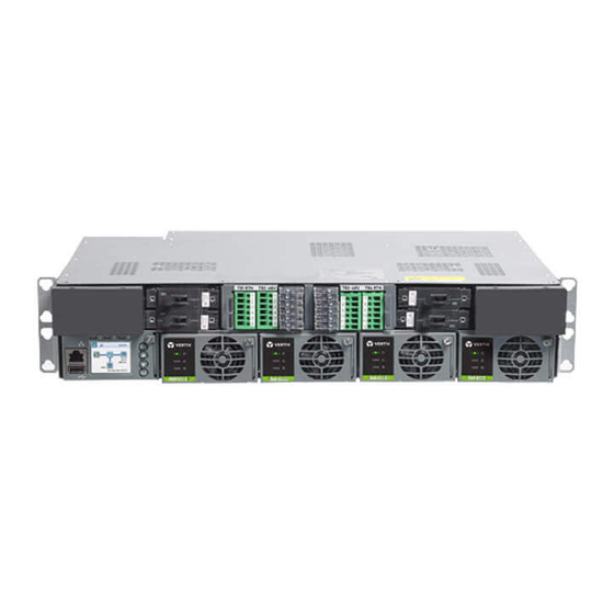
- Page 1 ™ NetSure -48 VDC Power System User Manual, UM582137200 (Revision A, January 11, 2017) Specification Number: 582137200 Model Number: NetSure ™ 5100...
- Page 2 NetSure ™ -48 VDC Power System User Manual, UM582137200 This page is intentionally blank. Spec. No: 582137200 Document Code: UM582137200 Model No: NetSure™ 5100 Revision A, January 11, 2017...
-
Page 3: Table Of Contents
NetSure ™ -48 VDC Power System User Manual, UM582137200 Table of Contents Admonishments Used in this Document ........................ ii Important Safety Instructions ..........................iii General Safety ................................iii Voltages .................................iii Battery ...................................iii Personal Protective Equipment (PPE) ........................v Hazardous Voltage ..............................v Handling Equipment Containing Static Sensitive Components ................. -
Page 4: Admonishments Used In This Document
NetSure ™ -48 VDC Power System User Manual, UM582137200 Admonishments Used in this Document DANGER! Warns of a hazard the reader will be exposed to that will likely result in death or serious injury if not avoided. (ANSI, OSHA) Danger WARNING! Warns of a potential hazard the reader may be exposed to that could result in death or serious injury if not avoided. -
Page 5: Important Safety Instructions
NetSure ™ -48 VDC Power System User Manual, UM582137200 Important Safety Instructions General Safety DC Output and Battery Voltages DANGER! DANGER! This system produces DC power and may YOU MUST FOLLOW APPROVED SAFETY PROCEDURES. have a battery source connected to it. Although the DC Danger Danger voltage is not hazardously high;... - Page 6 NetSure ™ -48 VDC Power System User Manual, UM582137200 DANGER! This equipment may be used in conjunction WARNING! A battery can present a risk of electrical shock and high short circuit current. Servicing of with lead-acid batteries. Working near lead-acid Warning Danger batteries should be performed or supervised only by...
-
Page 7: Personal Protective Equipment (Ppe)
NetSure ™ -48 VDC Power System User Manual, UM582137200 Personal Protective Equipment (PPE) Handling Equipment Containing Static Sensitive Components DANGER! ARC FLASH AND SHOCK HAZARD. Appropriate PPE and tools required when working on ALERT! Installation or removal of equipment containing Danger this equipment. -
Page 8: Static Warning
NetSure ™ -48 VDC Power System User Manual, UM582137200 Static Warning This equipment contains static sensitive components. The warnings listed below must be observed to prevent damage to these components. Disregarding any of these warnings may result in personal injury or damage to the equipment. Strictly adhere to the procedures provided in this document. -
Page 9: Customer Documentation Package
NOTE: The controller’s default “User Name” is "admin" and the default “Password” is “640275”. The NetSure 5100 consists of the following components mounted in a 19” or 23” wide relay rack or cabinet rack. Wall mounting •... -
Page 10: Estop Function
NetSure ™ -48 VDC Power System User Manual, UM582137200 ESTOP Function Table 1. Maintenance Procedures to be Performed at 6-Month Intervals If an ESTOP switch is wired to the IB2 Controller Interface Board, customer-furnished system ground applied to terminal Digital Procedure Referenced In Input #8 (+) activates the ESTOP function. - Page 11 NetSure ™ -48 VDC Power System User Manual, UM582137200 main module mounting assembly. Refer to Figure 1 NOTE: Compliance with Telcordia GR-1089-CORE requires that prior to mounting the system to the hardware build-up and torque. equipment rack: Disconnect the cable coming from the distribution unit •...
- Page 12 NetSure ™ -48 VDC Power System User Manual, UM582137200 Figure 1. Installing a Field Expansion Rectifier Shelf (cont’d on next page) 23” Front AC Option Shown. 19” Rear AC Option Similar. 1. Remove rear shield from the main module mounting assembly. This shield will not be reused.
- Page 13 NetSure ™ -48 VDC Power System User Manual, UM582137200 Figure 1. Installing a Field Expansion Rectifier Shelf (cont’d from previous page, cont’d on next page) 5. Install the busbars provided with the expansion module mounting assembly between the shelves. Torque to52 in-lbs. Do this by removing the hardware from the main shelf busbars, loosening the hardware on the expansion shelf busbars,...
- Page 14 NetSure ™ -48 VDC Power System User Manual, UM582137200 Figure 1. Installing a Field Expansion Rectifier Shelf (cont’d from previous page) 6. Install the new rear shields supplied with the expansion module mounting assembly to the main module mounting assembly. 7.
- Page 15 NetSure ™ -48 VDC Power System User Manual, UM582137200 Figure 2. Installing a Field Expansion Rectifier Shelf - Controller CAN Bus Termination Resistor Distribution Unit P/N 548398 with List 01 Distribution Unit These Are Factory Termination These Are Factory Connected Together Resistor P/N Connected Together List 01 Main Shelf...
-
Page 16: Troubleshooting And Repair
NetSure ™ -48 VDC Power System User Manual, UM582137200 Troubleshooting and Repair setpoint will be 100% of the combined capacity including the new rectifier module. Contact Information If a rectifier module is removed from the system (and the Rect Support contact information is provided at the back of this Comm Fail is cleared), the current limit point will remain document. -
Page 17: Replacement Information
NetSure ™ -48 VDC Power System User Manual, UM582137200 Replacement Information Replacing a GMT Distribution Fuse Replacement Assemblies Procedure When a trouble symptom is localized to a faulty rectifier, Refer to Figure 3 and replace the fuse. Ensure a safety controller, or system circuit card;... - Page 18 NetSure ™ -48 VDC Power System User Manual, UM582137200 Figure 3. GMT Distribution Fuse Replacement (List BA, BC, BF, LC, NA, NC, NF) Front GMT Fuse List BA shown, List BC, BF, LC, NA, NC, NF similar. Safety Cover Figure 4. Installation of Safety Fuse Covers Safety Cover Safety Cover...
- Page 19 NetSure ™ -48 VDC Power System User Manual, UM582137200 Figure 5. Replacing a Bullet Nose Circuit Breaker (List BA,NA) Insert these terminals into corresponding sockets on distribution unit. Front Position Towards Longer Side Center of Breaker Insert these terminals into Shorter Side Load Distribution corresponding...
-
Page 20: Circuit Card Replacement Procedures
NetSure ™ -48 VDC Power System User Manual, UM582137200 Orient the replacement circuit card over its mounting CIRCUIT CARD REPLACEMENT PROCEDURES position, and secure with the screws removed from the old circuit card. DANGER! Adhere to the “Important Safety Instructions” presented at the front of this document. - Page 21 NetSure ™ -48 VDC Power System User Manual, UM582137200 Performing this procedure may activate external alarms. the wire end with electrical tape. Repeat for each wire to be removed. Do one of the following. If possible, disable these alarms. If these alarms cannot be easily disabled, notify the Unplug all connectors plugged into the circuit card.
- Page 22 NetSure ™ -48 VDC Power System User Manual, UM582137200 Figure 7. Circuit Card Locations Rear Rear System Interface Board Slide Out Tray with Slide Out Tray with IB4 Board Installed IB2 Board Installed The IB2 Controller Interface Board The IB4 Second Controller Ethernet Port Board System Interface Board Can Be Installed in the Distribution Unit USB-A Port...
- Page 23 NetSure ™ -48 VDC Power System User Manual, UM582137200 Figure 8. System Interface Circuit Card Replacement System Interface Board Rear System Interface Board A CAN termination plug (P/N 548398) must be installed if an external device or system is not System Interface Board P/N 562209 connected here.
- Page 24 NetSure ™ -48 VDC Power System User Manual, UM582137200 Figure 9. IB2 or IB4 Circuit Card Replacement Rear The IB2 Controller Interface Board The IB4 Second Controller Ethernet Port Board Can Be Installed in the Distribution Unit Slide Out Tray with IB4 Board Installed Slide Out Tray with IB2 Board Installed...
-
Page 25: Netperform™ Optimization Services
NetPerform™ Optimization Services At Emerson Network Power, we understand the importance of reliable equipment – it’s critical to both your business and your bottom line. That is why we offer a wide array of services to meet all of your network infrastructure needs. - Page 26 NetSpan™, NetSure™ and NetXtend™ are trademarks of Emerson Network Power, Energy Systems, North America, Inc. Any other product, brand, or company names or logos are the property of the respective owner. While every precaution has been taken to ensure accuracy and completeness herein, Emerson Electric Co. assumes no responsibility, and disclaims all liability, for damages resulting from use of this information or for any errors or omissions.
Need help?
Do you have a question about the NetSure 5100 and is the answer not in the manual?
Questions and answers