Table of Contents
Advertisement
Quick Links
Advertisement
Table of Contents

Related Manuals for Gefen 4x1 DVI Switcher


Summary of Contents for Gefen 4x1 DVI Switcher
- Page 1 ®...
-
Page 2: Asking For Assistance
Chatsworth, CA 91311 www.gefen.com support@gefen.com Gefen LLC reserves the right to make changes in the hard ware, packaging and any accompanying doc u men ta tion without prior written notice. 4x1 DVI Switcher is a trademark of Gefen LLC © 2011 Gefen LLC, All Rights Reserved... -
Page 3: Table Of Contents
IR Remote Control Unit Layout and Description Installing the Battery Setting the IR channel on the Remote Setting the IR channel on the 4x1 DVI Switcher 12 Connecting the 4x1 DVI Switcher Wiring Diagram 13 Operating the 4x1 DVI Switcher... -
Page 4: Introduction
DVI source in a studio or lab situation. A plug-and-play solution, the 4x1 DVI Switcher shares one DVI display with up to four computers or other DVI video sources, saving space on your desktop. -
Page 5: Operation Notes
OPERATING THE GEFEN 4X1 DVI SWITCHER • The 4x1 DVI Switcher will take any of up to four (4) DVI single-link resolution inputs and switch them, one at a time, to a DVI output device such as a display/monitor or projector. Resolutions up to 1920x1200 are supported. -
Page 6: Features
Serial RS-232 remote port for switching via automated control or PC • Supports DDWG standards for DVI monitors Package Includes: (1) 4x1 DVI Switcher (4) 6 ft. DVI cables (1) IR Remote Control Unit (1) 5V DC Power Supply (1) User Manual... -
Page 7: Front Panel Layout
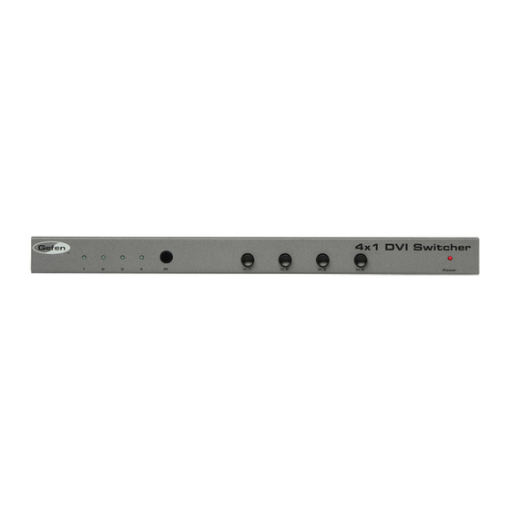
FRONT PANEL LAYOUT... -
Page 8: Front Panel Descriptions
FRONT PANEL DESCRIPTIONS Input Indicators (1 - 4) Each of these LED indicators glows bright blue according to the current DVI input selection (see Input Buttons, below) Receives IR signals from the included IR Remote Control Unit. Input Buttons (1 - 4) Pressing each of these buttons selects the desired DVI input source (1 - 4). -
Page 9: Back Panel Layout
BACK PANEL LAYOUT... -
Page 10: Back Panel Descriptions
RS-232 This port is used for serial communication using an RS-232 control device. For details, refer to page 16. Ext IR Connect an IR extender (Gefen part no. EXT-RMT-EXTIR) cable to this port. -
Page 11: Ir Remote Control Unit
IR REMOTE CONTROL UNIT Activity Indicator This LED will be activated momentarily each time a button is pressed. Source Selection Buttons (1 - 4) These buttons are used to select which source is routed to a monitor. NOTE: An Activity Indictor that fl ashes quickly while holding down any one of the sixteen buttons indicates a low battery. -
Page 12: Installing The Battery
IR REMOTE CONTROL UNIT Remove the battery cover on the back of the IR Remote Control Unit. Insert the included battery into the open battery slot. The positive (+) side of the battery should be facing up. Replace the battery cover. The Remote Control unit ships with two batteries. -
Page 13: Setting The Ir Channel On The Remote
IR Remote Control unit are set to IR channel 0 (both DIP switches down), then the 4x1 DVI Switcher must also be set to IR channel 0. See the next page for details on how to change the IR channel on the 4x1 DVI Switcher. -
Page 14: Setting The Ir Channel On The 4X1 Dvi Switcher
Switcher, both the Remote and the Switcher must be set to the same IR channel. The 4x1 DVI Switcher has a bank of eight (8) DIP switches on the bottom of the unit. DIP switch 7 and 8 are used to set the IR channel for the Switcher. DIP switches 1 - 6 are reserved for future expansion. -
Page 15: Connecting The 4X1 Dvi Switcher
Switcher and RS-232 host controller. OPTIONAL: To extend the range of the IR control, connect an IR Extender (Gefen part no. EXT-RMT-EXTIR) to the back of the Switcher. Connect the included 5V locking power supply to the power receptacle on the 4x1 DVI Switcher Connect the AC power cord to an available electrical outlet. -
Page 16: Operating The 4X1 Dvi Switcher
OPERATING THE 4X1 DVI SWITCHER Front Panel Buttons and LED Indicators The front panel of the 4x1 DisplayPort Switcher has a set of four (4) LED indicators, displaying which input (source) is being displayed. Each of these LED indicators corresponds to one of the push-buttons on the front panel. -
Page 17: Switching Sources Using The Ir Remote Control Unit
OPERATING THE 4X1 DVI SWITCHER Switching sources using the IR Remote Control Unit Example: Switch to Input 1 using the IR Remote Control: Press button 1 on the IR Remote Control Unit. The Activity Indicator on the IT Remote Control Unit will glow yellow, indicating that a button was pressed. -
Page 18: Switching Sources Using Rs-232
OPERATING THE 4X1 DVI SWITCHER Switching sources using RS-232 Confi gure the Switch for use with RS-232 (see page 14 for details). Example: Switch to input 4 using RS-232 Type 4 then press the Enter key to route the Switcher to Input 4. See page 15 for additional information on RS-232 commands. -
Page 19: Rs-232 Control
Only pins 2 (Receive), 3 (Transmit), and 5 (Ground) are used for communication. A null-modem adapter should not be used with this product. 5 4 3 2 1 9 8 7 6 Only Pins 2 (RX), 3 (TX), and 5 (Ground) are used on the RS-232 serial interface Bits per second ... -
Page 20: Specifi Cations
SPECIFICATIONS Maximum Pixel Clock...165 MHz Input Video Signal...1.2 Volts p-p Input DDC Signal...5 Volts p-p (TTL) DVI Input Connectors...(4) DVI-I 29-pin female (digital only) DVI Output Connectors...(1) DVI-I 29-pin female (digital only) RS-232 Connector...(1) DB-9, female IR Extender Connector... (1) 3.5 mm mini-stereo Power Supply...5 V DC Power Consumption...10 Watts (max.) Dimensions...14”... -
Page 21: Warranty
Gefen warrants the equipment it manufactures to be free from defects in material and workmanship. If equipment fails because of such defects and Gefen is notifi ed within two (2) years from the date of shipment, Gefen will, at its option, repair or replace the equipment, provided that the equipment has not been subjected to mechanical, electrical, or other abuse or modifi... - Page 22 Rev A7 This product uses UL listed power supplies.
Need help?
Do you have a question about the 4x1 DVI Switcher and is the answer not in the manual?
Questions and answers