
Related Manuals for Gefen 4x2 HDMI


Summary of Contents for Gefen 4x2 HDMI
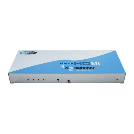
- Page 1 ® 4x2 Switcher for HDMI E X T - H D M I - 4 2 2 U S E R ' S M A N U A L www.gefen.com...
-
Page 2: Asking For Assistance
Chatsworth, CA 91311 www.gefen.com support@gefen.com Gefen, LLC reserves the right to make changes in the hard ware, packaging and any accompanying doc u men ta tion without prior written notice. 4x2 Switcher for HDMI is a trademark of Gefen, LLC HDMI is a trademark of hdmi.org... -
Page 3: Table Of Contents
TABLE OF CONTENTS 1 Introduction 2 Features 3 Panel Descriptions 4 Connecting and Operating the 4x2 Switcher for HDMI 5 RMT-4IR Installation 6 IR Code Confi guration 7 EDID Management Feature 8 EDID Management Modes 9 RS-232 Serial Communication 10 RS-232 Serial Communication Commands 11 Specifi... -
Page 4: Introduction
Our Commitment Gefen will always offer the fi nest quality product at the best possible price. Included in that price is a lifetime support from a team of outstanding engineers. The Gefen 4x2 Switcher for HDMI allows four HDTV HDMI devices to be switched easily in to two HDTV HDMI compatible monitors or projectors. -
Page 5: Features
FEATURES Features • Switches easily between any four HDMI sources • Maintains 480i, 480p, 720p, 720i, and 1080i, 1080p resolutions • Maintains highest HDMI single link video resolution • Maintains highest HDMI digital audio signal • Includes SPDIF output for easy hookup to digital audio systems •... -
Page 6: Panel Descriptions
PANEL DESCRIPTIONS... -
Page 7: Connecting And Operating The 4X2 Switcher For Hdmi
CONNECTING AND OPERATING THE 4x2 Switcher for HDMI How to Connect the 4x2 Switcher for HDMI to your devices 1 Connect the supplied cables from the HDTV HDMI sources into the 4x2 Switcher for HDMI inputs. 2 Connect the cables from your displays (monitor or projector) into the HDMI outs of the 4x2 Switcher for HDMI. -
Page 8: Rmt-4Ir Installation
1. Remove battery cover from the back of the RMT-4IR remote. 2. Verify that dip switches 1 & 2 are in the down (OFF) position. 3. Insert the battery, hold the battery so that you can see the positive side facing up. The side that is not marked must be facing down. -
Page 9: Ir Code Confi Guration
Remote Channel 3: The IR channel DIP switches for the 4x2 Switcher for HDMI are located on an 8 bank DIP switch inside of the unit and on its main-board. To open the unit, remove all screws on the underside and side of the unit. -
Page 10: Edid Management Feature
The user has the option, through a combination of DIP switch settings within the 4x2 Switcher for HDMI, to choose how the unit will manage the EDID from multiple HDMI devices/displays. -
Page 11: Edid Management Modes
EDID MANAGEMENT MODES EDID Modes The diagram below illustrates the 8 DIP switch bank. Use DIP switches 1, 2, 5, and 7 to select the desired EDID management mode. EDID Mode 0 (Switch 1=OFF Switch2=OFF Switch5=ON) • Edid is copied from the device connected to the fi rst active hdmi output port. -
Page 12: Rs-232 Serial Communication
• Switching/routing of inputs to outputs without the RMT-4IR remote control. • Switch EDID management modes without opening the unit to physically modify DIP switches. • Change IR code channel without opening the unit to physically modify DIP switches. -
Page 13: Rs-232 Serial Communication Commands
RS-232 SERIAL COMMUNICATION COMMANDS Switching/Routing Binary Table ASCII RMT-4IR Button EDID Management Modes All DIP switches inside the unit must be in their default OFF position. Use the ASCII commands below to change the EDID modes. For a description of each mode please see page 8. -
Page 14: Specifications
SPECIFICATIONS Video Amplifi er Bandwidth ... 165 MHz Input Video Signal ... 1.2 volts p-p Input DDC Signal ... 5 volts p-p (TTL) Single Link Range ..1080p / 1920 x 1200 Input Connector Type ... HDMI Output Connector Type ...HDMI Output Audio Connector Type... - Page 16 Rev X1 20600 Nordhoff St, Chatsworth CA 91311 1-800-545-6900 818-772-9100 fax: 818-772-9120 www.gefen.com support@gefen.com...
Need help?
Do you have a question about the 4x2 HDMI and is the answer not in the manual?
Questions and answers