Table of Contents
Advertisement
Installation and Operation Data
Installation and
Operation Manual
®
Jandy
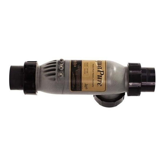
AquaPure
Electronic Chlorine
Generator
APURE700 and APURE1400
Patent Pending
FOR YOUR SAFETY - This product must be installed and serviced by a pro fes sion al pool/spa
service technician. The procedures in this manual must be followed ex act ly. Failure to follow
warning notices and instructions may result in property damage, serious injury, or death.
™
WARNING
Advertisement
Table of Contents


Need help?
Do you have a question about the AquaPure APURE700 and is the answer not in the manual?
Questions and answers