Table of Contents
Advertisement
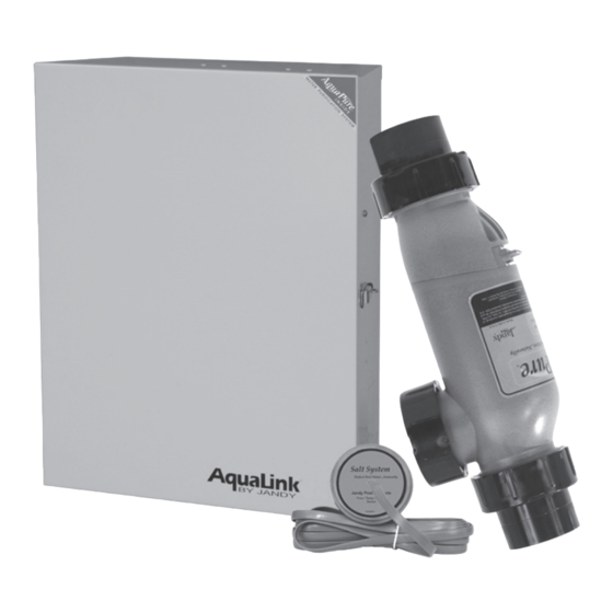
Jandy
AquaPure
Salt Water Chlorinator
PureLink™
Water Purification System
Power Center and Cell Kit
Models:
APUREM
PLC700
PLC1400
WARNING
FOR YOUR SAFETY: This product must be installed and serviced by a contractor who is licensed and qualified
in pool equipment by the jurisdiction in which the product will be installed where such state or local requirements
exists. In the event no such state or local requirement exists, the installer or maintainer must be a professional with
sufficient experience in pool equipment installation and maintenance so that all of the instructions in this manual
can be followed exactly. Before installing this product, read and follow all warning notices and instructions that
accompany this product. Failure to follow warning notices and instructions may result in property damage, personal
injury, or death. Improper installation and/or operation will void the warranty.
Electronic
®
And
If these instructions are not followed exactly, a fire or explosion may
result, causing property damage, personal injury, or death.
INSTALLATION AND
OPERATION MANUAL
ENGLISH
Advertisement
Table of Contents

Subscribe to Our Youtube Channel
Related Manuals for Jandy APUREM


Summary of Contents for Jandy APUREM
- Page 1 ® Salt Water Chlorinator PureLink™ Water Purification System Power Center and Cell Kit Models: APUREM PLC700 PLC1400 If these instructions are not followed exactly, a fire or explosion may WARNING result, causing property damage, personal injury, or death. FOR YOUR SAFETY: This product must be installed and serviced by a contractor who is licensed and qualified in pool equipment by the jurisdiction in which the product will be installed where such state or local requirements exists.
-
Page 2: Table Of Contents
Page 2 Page 2 ENGLISH ENGLISH Jandy AquaPure /PureLink™ Power Center and Cell Kit Installation and Operation Manual ® ® Table of Contents Section 5. Operating Instructions ....32 Section 1. Important Safety Instructions ..5 User Interface Controls ........32 Section 2. - Page 3 Page 3 Page 3 Jandy AquaPure /PureLink™ Power Center and Cell Kit Installation and Operation Manual ® ® ENGLISH ENGLISH Figures Figure 1. Typical AquaPure and PureLink Installation Figure 20a. AquaPure Control Center ...... 46 Example With Options ......8 Figure 20b.
-
Page 4: Section 1. Important Safety Instructions
Page 4 Page 4 ENGLISH ENGLISH Jandy AquaPure /PureLink™ Power Center and Cell Kit Installation and Operation Manual ® ® Section 1. Important Safety Instruction READ AND FOLLOW ALL INSTRUCTIONS All electrical work must be performed by a licensed electrician and conform to all national, state, and local codes. - Page 5 Page 5 Page 5 Jandy AquaPure /PureLink™ Power Center and Cell Kit Installation and Operation Manual ® ® ENGLISH ENGLISH WARNING Prolonged immersion in hot water may induce hyperthermia. Hyperthermia occurs when the internal temperature of the body reaches a level several degrees above the normal body temperature of 98.6°F (37°C). The symptoms of hyperthermia include dizziness, fainting, drowsiness, lethargy, and an increase in the internal temperature of the body.
- Page 6 Page 6 Page 6 ENGLISH ENGLISH Jandy AquaPure /PureLink™ Power Center and Cell Kit Installation and Operation Manual ® ® CAUTION It is important to note that certain materials used in and around swimming pools and spas may not be compatible with chemicals commonly used to purify pool and spa water (e.g.
-
Page 7: Section 2. System Description
Page 7 Page 7 Jandy AquaPure /PureLink™ Power Center and Cell Kit Installation and Operation Manual ® ® ENGLISH ENGLISH Section 2. System Description ORP Unit Options List (Control Signal from ORP Unit to 1. ORP/External Control Interface ORP Interface/Aux Board) 2. -
Page 8: Electrical Specifications
Page 8 Page 8 ENGLISH ENGLISH Jandy AquaPure /PureLink™ Power Center and Cell Kit Installation and Operation Manual ® ® PureLink • The PureLink system integrates a salt water chlorinator control system and Power Center power center for use with AquaLink Pool/Spa Automation systems (not including (for PureLink AquaLink Z4). -
Page 9: Figure 2A. Wiring Diagram For The Purelink
Page 9 Page 9 Jandy AquaPure /PureLink™ Power Center and Cell Kit Installation and Operation Manual ® ® ENGLISH ENGLISH Flow, Salinity, Temp Sensors CHLORINE GENERATOR Factory wired to Multiplex Board USER INTERFACE ® To AquaLink PRIMARY CHLORINE GENERATOR TRANSFORMER... - Page 10 Page 10 Page 10 ENGLISH ENGLISH Jandy AquaPure /PureLink™ Power Center and Cell Kit Installation and Operation Manual ® ® Flow, Salinity, Temp Sensors CHLORINE GENERATOR Factory wired to Multiplex Board USER INTERFACE ® To AquaLink PRIMARY CHLORINE GENERATOR TRANSFORMER...
-
Page 11: Figure 2C. Wiring Diagram For The Aquapure
Page 11 Page 11 Jandy AquaPure /PureLink™ Power Center and Cell Kit Installation and Operation Manual ® ® ENGLISH ENGLISH RIBBON CABLE TO Power Center Wiring Diagram USER INTERFACE CHLORINE GENERATOR USER INTERFACE PRIMARY LOW VOLTAGE RACEWAY CHLORINE GENERATOR TRANSFORMER... -
Page 12: Section 3. Installation Instructions
Page 12 Page 12 ENGLISH ENGLISH Jandy AquaPure /PureLink™ Power Center and Cell Kit Installation and Operation Manual ® ® Section 3. Installation Instructions 3.1 Materials and Tools NOTE Salt not included. See Section 4, Pool Water Preparation. Installation Materials Furnished... -
Page 13: Recommended Plumbing Configuration
Page 13 Page 13 Jandy AquaPure /PureLink™ Power Center and Cell Kit Installation and Operation Manual ® ® ENGLISH ENGLISH Flow Sensor Flow Sensor Flow Sensor Figure 3. Chlorine Generator Cell and Sensor Orientation with Flow Direction 3.2.2 Recommended Plumbing Configuration The preferred installation is that the cell and sensor are plumbed in the common line after (downstream) the heater. -
Page 14: Installing Aquapure And Purelink Control/Power Centers
Page 14 Page 14 ENGLISH ENGLISH Jandy AquaPure /PureLink™ Power Center and Cell Kit Installation and Operation Manual ® ® Control/Power Center Heater Cell Pool Sensor Return Figure 5. Recommended Plumbing Configuration for Pool or Dual Equipment Systems 3.3 Installing AquaPure and PureLink Control/Power Centers NOTE The control/power center should be located at or near the equipment pad. -
Page 15: Earth Bonding (Grounding)
Page 15 Page 15 Jandy AquaPure /PureLink™ Power Center and Cell Kit Installation and Operation Manual ® ® ENGLISH ENGLISH Mark Holes on Mounting Surface 4" 4" Mounting Bracket Figure 7. Mark Holes using Control/Power Center Mounting Bracket Reinstall the mounting brackets to the top and bottom of the back of the control/power center using the four (4) screws that were removed in Step 2. -
Page 16: Model Configuration
L-Bracket Page 16 Page 16 ENGLISH ENGLISH Jandy AquaPure /PureLink™ Power Center and Cell Kit Installation and Operation Manual ® ® 3.5 Model Configuration The chlorine generator Power Interface Board (PIB) is configured as a 1400 model by factory default. -
Page 17: Installing The Electrolytic Cell And Flow/Temp/Salinity Sensor
Page 17 Page 17 Jandy AquaPure /PureLink™ Power Center and Cell Kit Installation and Operation Manual ® ® ENGLISH ENGLISH 3.7 Installing the Electrolytic Cell and Flow/Temp/Salinity Sensor Please choose one of the following instructions to either install or replace the cell and sensor assembly. -
Page 18: Replacement Of Existing 3-Port Cell (Universal Or 2" Pvc Unions)
Page 18 Page 18 ENGLISH ENGLISH Jandy AquaPure /PureLink™ Power Center and Cell Kit Installation and Operation Manual ® ® Connect the DC cord to the power center. Feed the DC cord through the same strain relief fitting as the flow/temp/salinity sensor. -
Page 19: Replacement Of Old 2-Port (Square) Cell With New 3-Port Cell
Page 19 Page 19 Jandy AquaPure /PureLink™ Power Center and Cell Kit Installation and Operation Manual ® ® ENGLISH ENGLISH Connect the DC cord to the control center. Feed the DC cord through the same strain relief fitting as the flow/temp/salinity sensor. Plug the DC cord into the two spade connectors of the wiring harness as shown in Figures 2a, 2b, and 2c. - Page 20 Page 20 Page 20 ENGLISH ENGLISH Jandy AquaPure /PureLink™ Power Center and Cell Kit Installation and Operation Manual ® ® 3a. Option 1 - Retain Existing Sensor in Threaded Tee a. Remove old 2-Port cell body by unscrewing coupling nuts on ports. The cell body will be free to a.
-
Page 21: Figure 11. Cell Installation And Flow/Temp/Salinity Sensor
Page 21 Page 21 Jandy AquaPure /PureLink™ Power Center and Cell Kit Installation and Operation Manual ® ® ENGLISH ENGLISH Connect the DC cord to the control center. Feed the DC cord through the same strain relief fitting as the flow/temp/salinity sensor. -
Page 22: Figure 12. Pipe Cutout
Page 22 Page 22 ENGLISH ENGLISH Jandy AquaPure /PureLink™ Power Center and Cell Kit Installation and Operation Manual ® ® Universal Unions and Nuts For a 2" pipe, the cutout is 13⅞" with the full unions. For a 50 mm pipe, the cutout is 352 mm Sensor Port Plug and Nut with the full unions. -
Page 23: Connection Of Chlorine Generator Electronics To An Aqualink Control System
Power Connection between AquaPure Control Center and AquaLink Power Center The Jandy AquaLink and AquaPure use a four (4) wire connection to communicate. Any outdoor rated four (4) conductor cable, minimum 22 AWG, can be used. Locate the appropriate screw terminals on the circuit board according to Figure 15. - Page 24 Page 24 Page 24 ENGLISH ENGLISH Jandy AquaPure /PureLink™ Power Center and Cell Kit Installation and Operation Manual ® ® 3.8.2 Connection of PureLink Chlorine Generator Electronics to an AquaLink Control ® System The chlorine generator electronics in the PureLink Power Center and the AquaLink controller require a four (4) wire connection to communicate.
-
Page 25: Operation Of External Control/Orp Control Board
Page 25 Page 25 Jandy AquaPure /PureLink™ Power Center and Cell Kit Installation and Operation Manual ® ® ENGLISH ENGLISH 3.9 Operation of External Control/ORP Control Board An external device such as an ORP (Oxidation Reduction Potential) controller supplying 24 Volts AC can be used to control the output of the chlorine generator. -
Page 26: Section 4. Pool Water Preparation
Page 26 Page 26 ENGLISH ENGLISH Jandy AquaPure /PureLink™ Power Center and Cell Kit Installation and Operation Manual ® ® Section 4. Pool Water Preparation ATTENTION INSTALLER: Various application notes (including more detailed instructions) are available from the Dealer covering installation, operation, maintenance, and plumbing of the chlorinator system. - Page 27 Page 27 Page 27 Jandy AquaPure /PureLink™ Power Center and Cell Kit Installation and Operation Manual ® ® ENGLISH ENGLISH Chemistry You Need to Know Chlorine Stabilizer (cyanuric acid) is needed to maintain proper levels of chlorine. Most unstable chlorine is destroyed by the UV radiation from the sun within 2 hours. Chlorine stabilizer should be maintained between 50 - 75 PPM.
-
Page 28: Optimum Pool Water Conditions
Page 28 Page 28 ENGLISH ENGLISH Jandy AquaPure /PureLink™ Power Center and Cell Kit Installation and Operation Manual ® ® 4.5 Optimum Pool Water Conditions In accordance with Association of Pool and Spa Professionals (APSP ) standards, we recommend the ®... -
Page 29: Salt (Nacl Sodium Chloride)
Page 29 Page 29 Jandy AquaPure /PureLink™ Power Center and Cell Kit Installation and Operation Manual ® ® ENGLISH ENGLISH 4.7 Salt (NaCl sodium chloride) 4.7.1 When to Add Salt? For a new concrete pool or newly resurfaced pool it is recommended to wait 30 days (surface should be completely cured) before adding salt. -
Page 30: Approximate Kilograms (Pounds) Of Salt Needed To Obtain 3.0 Gpl (3,000 Ppm) In Pool
Page 30 Page 30 ENGLISH ENGLISH Jandy AquaPure /PureLink™ Power Center and Cell Kit Installation and Operation Manual ® ® Brush the pool bottom and allow water to circulate for 24 hours to dissolve completely and mix evenly with the pool water. -
Page 31: Section 5. Operating Instructions
Page 31 Page 31 Jandy AquaPure /PureLink™ Power Center and Cell Kit Installation and Operation Manual ® ® ENGLISH ENGLISH Section 5. Operating Instructions NOTE The user interface is located inside the control/power center. To access the control panel, open the door to the control/power center. -
Page 32: Reading The Display
Page 32 Page 32 ENGLISH ENGLISH Jandy AquaPure /PureLink™ Power Center and Cell Kit Installation and Operation Manual ® ® Operating User Interface Controls when AquaLink RS Control System is Online ® The user interface can be used to adjust the output production rate (%) when the salt... - Page 33 Page 33 Page 33 Jandy AquaPure /PureLink™ Power Center and Cell Kit Installation and Operation Manual ® ® ENGLISH ENGLISH The automatic cleaning cycle is in progress. The cleaning cycle is factory set and CELL REVERSING cannot be adjusted. Cell Reversing does not interrupt the production of chlorine.
-
Page 34: Operation
Page 34 Page 34 ENGLISH ENGLISH Jandy AquaPure /PureLink™ Power Center and Cell Kit Installation and Operation Manual ® ® 5.3 Operation CAUTION Before attempting to operate refer to Section 4, Pool Water Preparation. Also, do not adjust Chlorine production above 00% until it is certain that salt has been dissolved in pool. Operating without salt will damage the Electrolytic Cell. -
Page 35: Startup
Page 35 Page 35 Jandy AquaPure /PureLink™ Power Center and Cell Kit Installation and Operation Manual ® ® ENGLISH ENGLISH 5.4 Startup 5.4.1 Shocking Shock (superoxidation) (see Section 4.4, 6. Shocking) the pool water from an outside source at the time of pool startup to burn off contaminates. -
Page 36: Recommendations
Page 36 Page 36 ENGLISH ENGLISH Jandy AquaPure /PureLink™ Power Center and Cell Kit Installation and Operation Manual ® ® 5.6 Recommendations DO List • Read and keep your manual in a safe place. • Increase chlorine production rate before a large number of bathers enter the pool and return to normal afterwards. -
Page 37: Section 6. User Maintenance Instructions
Page 37 Page 37 Jandy AquaPure /PureLink™ Power Center and Cell Kit Installation and Operation Manual ® ® ENGLISH ENGLISH Section 6. User Maintenance Instructions The following information describes how to care for your sanitizing system. Important: Always test the chlorine levels of your pool before each use. -
Page 38: Flow/Temp/Salinity Sensor Cleaning
Page 38 Page 38 ENGLISH ENGLISH Jandy AquaPure /PureLink™ Power Center and Cell Kit Installation and Operation Manual ® ® WARNING Always turn pump off prior to installing or removing any components from the pool’s plumbing. Your pump/filter system is operated under pressure and pressure must be released before you begin to avoid system damage or personal injury. Open the air relief valve on your pool filter to release the pressure in the system. -
Page 39: Winterizing
Page 39 Page 39 Jandy AquaPure /PureLink™ Power Center and Cell Kit Installation and Operation Manual ® ® ENGLISH ENGLISH 6.4 Flow/Temp/Salinity Sensor Cleaning One time per year or as needed. It is rare but scale formations on the flow/temp/salinity sensor sometimes occur and will affect the accuracy of the salinity test. -
Page 40: Section 7. Troubleshooting
Page 40 Page 40 ENGLISH ENGLISH Jandy AquaPure /PureLink™ Power Center and Cell Kit Installation and Operation Manual ® ® Section 7. Troubleshooting NOTE: Turn off power to unit prior to attempting service or repair. 7.1 Problems and Corrective Action... - Page 41 Page 41 Page 41 Jandy AquaPure /PureLink™ Power Center and Cell Kit Installation and Operation Manual ® ® ENGLISH ENGLISH Problem Possible Cause Corrective Action “Cell On” indicator does not Chlorine Production set to 00%. Adjust CHLORINE PRODUCTION to desired come on. percentage. If No Flow also….
- Page 42 Page 42 Page 42 ENGLISH ENGLISH Jandy AquaPure /PureLink™ Power Center and Cell Kit Installation and Operation Manual ® ® Problem Possible Cause Corrective Action “Service” Indicator On. Low salt level in pool water. Test salinity. Add salt as described in Section 4.7.
-
Page 43: Level 2 Service Codes
Page 43 Page 43 Jandy AquaPure /PureLink™ Power Center and Cell Kit Installation and Operation Manual ® ® ENGLISH ENGLISH 7.2 Service Codes Code Number Possible Cause Corrective Action Low current in forward direction to Cell. 1. Clean cell if necessary (see Section 6.3). - Page 44 Page 44 Page 44 ENGLISH ENGLISH Jandy AquaPure /PureLink™ Power Center and Cell Kit Installation and Operation Manual ® ® Code Number Possible Cause Corrective Action Front board power supply either too low or too high. Contact a pool professional.
-
Page 45: Section 8. Temperature Conversion
Page 45 Page 45 Jandy AquaPure /PureLink™ Power Center and Cell Kit Installation and Operation Manual ® ® ENGLISH ENGLISH Section 8. Temperature Conversion To display Celsius or Fahrenheit on the digital display. Press and hold button for 15 POOL TEMP -BOOST- (D) seconds (third beep). -
Page 46: Section 9. Aquapure And Purelink Exploded Views And Replacement Kits
Page 46 Page 46 ENGLISH ENGLISH Jandy AquaPure /PureLink™ Power Center and Cell Kit Installation and Operation Manual ® ® Section 9. AquaPure and PureLink Exploded Views and Replacement Kits 9.1 AquaPure and PureLink Control/Power Center Replacement Parts Dwg.# Kit # Description Qty. -
Page 47: Figure 20B. Purelink Power Center, 6614Ap
Page 47 Page 47 Jandy AquaPure /PureLink™ Power Center and Cell Kit Installation and Operation Manual ® ® ENGLISH ENGLISH 4, 6 2, 3 Figure 20b. PureLink Power Center, 6614AP 4, 6 2, 3 Figure 20c. PureLink Power Center, 6613AP... -
Page 48: 3-Port Electrolytic Cell And Sensor Replacement Parts With Universal Unions (2"-2½")
Page 48 Page 48 ENGLISH ENGLISH Jandy AquaPure /PureLink™ Power Center and Cell Kit Installation and Operation Manual ® ® 9.2 3-Port Electrolytic Cell and Sensor Replacement Parts with Universal Unions (2”-2½”) 1, 2, 3 Dwg. Kit # Description Qty. -
Page 49: 3-Port Electrolytic Cell And Sensor Replacement Parts (2" Pvc Unions)
Page 49 Page 49 Jandy AquaPure /PureLink™ Power Center and Cell Kit Installation and Operation Manual ® ® ENGLISH ENGLISH 9.3 3-Port Electrolytic Cell and Sensor Replacement Parts (2” PVC Unions) 1, 8 Dwg. # Kit # Description Qty. R0475300 3-Port Cell, APURE700, 2”... - Page 50 Page 50 Page 50 ENGLISH ENGLISH Jandy AquaPure /PureLink™ Power Center and Cell Kit Installation and Operation Manual ® ® NOTES...
- Page 51 Page 51 Page 51 Jandy AquaPure /PureLink™ Power Center and Cell Kit Installation and Operation Manual ® ® ENGLISH ENGLISH NOTES...
- Page 52 UL STD 1081 2-3365 Mainway, Burlington, ON L7M 1A6 Canada CERTIFIED TO CAN/CSA C22.2 NO. 218.1 USA | Jandy.com | 1.800.822.7933 Certified to NSF/ANSI Standard 50 Canada | Jandy.ca | 1.888.647.4004 ©2021 Zodiac Pool Systems LLC. All rights reserved. ZODIAC ®...
Need help?
Do you have a question about the APUREM and is the answer not in the manual?
Questions and answers