Omron SYSMAC C200H-IDS01-V1 Operation Manual
Id sensor
Hide thumbs
Also See for SYSMAC C200H-IDS01-V1:
- Operation manual (51 pages) ,
- Operation manual (20 pages)
Table of Contents
Advertisement
Quick Links
Advertisement
Table of Contents

Related Manuals for Omron SYSMAC C200H-IDS01-V1


Summary of Contents for Omron SYSMAC C200H-IDS01-V1
- Page 1 Cat. No. W153-E1-04 SYSMAC C200H-IDS01-V1/IDS21 ID Sensor OPERATION MANUAL...
- Page 2 C200H-IDS01-V1/IDS21 ID Sensor Operation Manual Revised May 2003 IDS01-V1 IDS21 MACHINE MACHINE MONITOR MONITOR HEAD ANTENNA...
- Page 4 Notice: OMRON products are manufactured for use according to proper procedures by a qualified operator and only for the purposes described in this manual. The following conventions are used to indicate and classify precautions in this manual. Always heed the information provided with them. Failure to heed precautions can result in injury to people or dam- age to property.
-
Page 6: Table Of Contents
TABLE OF CONTENTS PRECAUTIONS ........Intended Audience ............General Precautions . - Page 7 TABLE OF CONTENTS Glossary ......... . Index .
-
Page 8: About This Manual
About this Manual: This manual explains the operation of two non-contact information detection systems: C200H–IDS01–V1 Electromagnetic Inductor ID Sensor Unit and C200H–ID21 Microwave ID Sensor Unit. Both Units, having long-range sens- ing capabilities, can read information from or write information to a Data Car- rier mounted to a moving work piece. - Page 10 PRECAUTIONS This section provides general precautions for using the C500-IDS @@ ID Sensors and related devices. The information contained in this section is important for the safe and reliable application of C500-IDS @@ ID Sensors. You must read this section and understand the information contained before attempting to set up or operate a PC system.
-
Page 11: Intended Audience
Intended Audience Intended Audience This manual is intended for the following personnel, who must also have knowledge of electrical systems (an electrical engineer or the equivalent). • Personnel in charge of installing control devices. • Personnel in charge of designing control systems. •... -
Page 12: Operating Environment Precautions
Operating Environment Precautions !WARNING Provide safety measures in external circuits, i.e., not in the Programmable Controller (CPU Unit including associated Units; referred to as "PC"), in order to ensure safety in the system if an abnormality occurs due to malfunction of the PC or another external factor affecting the PC operation. - Page 13 Application Precautions !WARNING Always heed these precautions. Failure to abide by the following precautions could lead to serious or possibly fatal injury. • Always connect to a ground of 100 Ω or less when installing the ID Sen- sor systems. Not connecting to a ground of 100 Ω or less may result in electric shock.
- Page 14 Application Precautions • Changing the operating mode of the PC. • Force-setting/force-resetting any bit in memory. • Changing the present value of any word or any set value in memory. • Resume operation only after transferring to the new CPU Unit the con- tents of the DM Area, HR Area, and other data required for resuming operation.
- Page 15 Application Precautions...
-
Page 16: System Description And Installation
SECTION 1 System Description and Installation This section describes the features, components, configuration, and installation of the ID Sensor systems. System Description ..........Features . -
Page 17: System Description
The following diagram illustrates two ID Sensor systems, one using a C200H- IDS01-V1 ID Sensor and one using a C200H-IDS21 ID Sensor. C200H ID Sensor Systems Microwave ID Sensor Electromagnetic Induction ID Unit (C200H-IDS21) Sensor Unit (C200H-IDS01-V1) Connecting Cable Connecting Cable Connecting Cable Hand-held Program- Hand-held Program-... -
Page 18: Features
Note Refer to the list of applicable manuals in the About this Manual section. Differences between The C200H-IDS01-V1, which is an updated version of the C200H-IDS01, has C200H-IDS01 and the following three new features in addition to all the capabilities that the C200H-IDS01-V1 C200H-IDS01 possesses. - Page 19 Features Section 1-2 2. New Commands The C200H-IDS01-V1 incorporates data management commands, with which it is possible to check the reliability of the Data Carrier’s data. The details of the commands are as follows: Function Command Meaning Checking of data MD-K By adding a check code to the Data Carrier’s data, it is possible to detect a data...
-
Page 20: Components And Indicators
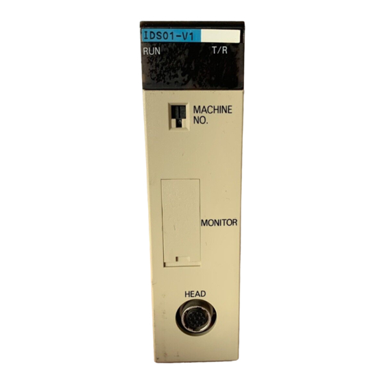
Components and Indicators Section 1-3 Components and Indicators Although similar in appearance, note that the C200H-IDS01-V1 ID Sensor reads or writes data through a Read/Write Head and the C200H-IDS21 reads or writes data through a Read/Write Antenna. C200H-IDS01-V1 Front Panel... -
Page 21: System Configuration
Note The user can select the communications distance priority mode or communications speed priority mode with pin 2 of the DIP switch when the C200H-IDS01-V1 accesses the EEPROM Data Carrier. Neither of these modes are, however, available when the ID Sensor Unit accesses the SRAM Data Carrier or when the C200H-IDS21 ac- cesses any Data Carrier, in which case turn pin 2 OFF. -
Page 22: System Connections
System Connections Section 1-5 C200H-IDS01-V1 Electromagnetic Induction ID Sensor ID Sensor Unit C200H C200H Connecting Cable Read/Write Read/ Read/Write data Write Head Head Movement Data Carrier Work Work piece Hand-held Programming Console (Attach the keyboard accessory sheet, supplied with the ID Sensor Unit, to the Programming Console.) - Page 23 System Connections Section 1-5 The information in this table applies only when no other Special I/O Units are mounted to other Racks (PC or Expansion I/O Racks) and the Units in this table are mounted only to a Remote I/O Slave Rack. High-speed High-density I/O Temperature...
-
Page 24: Maximum Distance Between Id Sensor Unit And R/W Head
Maximum Distance Between ID Sensor Unit and R/W Head Section 1-6 Maximum Distance Between ID Sensor Unit and R/W Head R/W Head C500 C200 IDS01-V1 IDS01-V2 IDS02 IDS02-V1 IDS01 IDS01-V1 V600-H52 50.5 m 10 m 50.5 m (V600-D23P52) (V600-D23P54) V600-H51 50.5 m 10 m 50.5 m... -
Page 26: Operation
SECTION 2 Operation This section describes operation of the ID Sensor Units, and covers switch settings, bit allocation, and communication commands, and introduces the user program. Switch Settings ..........Word Settings . -
Page 27: Switch Settings
Switch Settings Section 2-1 Section Overview This section contains information on switch settings, bit allocation, and setup of both ID Sensor systems, as well as explanations of the user program, com- munication commands, and the write-protect function. Switch Settings Unit Number Switch Before beginning operation, use the unit number switch on the front panel to set the unit number (0 through 9) of the ID Sensor Unit. -
Page 28: Word Settings
Word Settings Section 2-2 Word Settings Words 100 through 199 in the IR area of the PC are reserved for Special I/O Units. Each Special I/O Unit is assigned ten words, of which five are needed. These five words, used by the ID Sensor or other Special I/O Units for data communication, are referred to as I/O refresh data (stored in the I/O refresh data area). - Page 29 Word Settings Section 2-2 IR Bit Allocation Word Bit number Bit name Function Command At the leading edge of the signal, the ID Sensor Unit reads execution flag and executes the command. Error reset flag While the ID Sensor Unit is waiting for a command, the error reset flag is turned ON and the error flags in word n+4, bits 08 through 15 are turned OFF.
- Page 30 Word Settings Section 2-2 Word Bit number Bit name Function ID busy This flag turns ON while the ID Sensor Unit is executing a command. Waiting for Data During the execution of Auto Read or Auto Write, this flag is Carrier ON while it is waiting for the Data Carrier to approach the Read/Write Head (or Antenna).
- Page 31 Word Settings Section 2-2 Read/Write Bit Areas The following table shows the memory areas (bits) that the ID Sensor Unit uses when reading data from or writing data to the Data Carrier. Area Bits DM area DM 0000 through 1999 IR area 000 through 246 HR area...
-
Page 32: The User Program
The User Program Section 2-3 The User Program The ID Sensor Unit will not function unless the PC is programmed to control the operation of the Unit. The Unit communicates with the Data Carrier through the Read/Write Head by means of the commands provided by the user program of the PC. - Page 33 The User Program Section 2-3 Writing Data to the Data The CPU, via the Write, Auto Write, and Clear-all commands, directs the ID Carrier from the CPU Sensor Unit to write data to the Data Carrier. The following diagram shows how the program writes data to the Data Carrier.
-
Page 34: Communication Commands
ID Sensor Unit is initialized and waits for the next command. Data management 4D 44 Checks the Data Carrier’s internal memory. The reliability of data is (C200H-IDS01-V1 checked using the MD-K and MD-C commands and the number of only) overwriting operations is checked using the MD-L and MD-S commands. - Page 35 The User Program Section 2-3 Write Command This command writes data to the internal memory of the Data Carrier. Up to 1024 bytes (512 words) of data can be written per scan. Specify the first address in hexadecimal. This is OP (operation) code indicating that the command is Write.
- Page 36 The User Program Section 2-3 Read Command The Read command reads data from the internal memory of the Data Carrier. Up to 1024 bytes (512 words) of data can be read at a time. Specify the first address and the number of bytes in hexadecimal. This is OP (operation) code indicating that the command is Read.
- Page 37 The User Program Section 2-3 Auto Write Command The Auto Write command executes when the Data Carrier approaches the Read/Write Head. When the Data Carrier comes within detection range of the Read/Write Head, Auto Write writes data to the internal memory of the Data Carrier.
- Page 38 The User Program Section 2-3 Auto Read Command Auto Read executes when the Data Carrier approaches the R/W Head. When the Data Carrier comes within detection range of the R/W Head, Auto Read reads data from the internal memory of the Data Carrier. Up to 1024 bytes (512 words) of data can be read at a time.
- Page 39 The User Program Section 2-3 Auto Read/Write Abort This command aborts Auto Read and Auto Write. When this command is exe- cuted, the ID Sensor Unit is initialized and waits for the next command. This is OP (operation) code indicating that the command is Auto Read/Write Abort.
- Page 40 The User Program Section 2-3 The number of check area bytes is 256 (0100) maximum and the number of command data words is fixed at 5. Memory management command Select K to designate R/W Head no. (fixed to 1) data check code calculation and C to designate data check 4B/43...
- Page 41 The User Program Section 2-3 Address 0000 0001 First address Check code calculation area (no. of check bytes − 2) No. of area bytes Check area CRC (upper digit) Check code area (2 bytes) CRC (lower digit) Note The last two bytes of a check area are for the check code area, to which noth- ing must be written.
- Page 42 The User Program Section 2-3 Command Add an appropriate number (up to 255 (00FF)) to the data of the address des- ignated by the user in order to judge if the address has been overwritten 100,000 times. If 0 (0000) is added, only the life of the address will be checked.
- Page 43 The User Program Section 2-3 Usage: Using the write command, write in advance the number of desired overwriting operations onto the overwriting operation management area of the DC. After writing data to the most frequently used address, renew the number of overwriting operations in order to check the life of the EEPROM.
-
Page 44: Data Carrier Memory
The User Program Section 2-3 When the command is executed and the address is found to have been over- written for the number of operations set by the user, the Data Carrier warning flag will be turned ON. Command Processing: Overwriting operation management area consists of three bytes from the first address, from which the appropriate number is subtracted. -
Page 45: Write Protection Function
The User Program Section 2-3 Data Carrier Memory Map Data Carrier With a Memory Capacity of Data Carrier With a Memory Capacity of 256 Bytes Maximum More Than 256 Bytes Data Data Address Address 0000 0000 Write protected setting area Production month and year area 0001 0001... - Page 46 The User Program Section 2-3 Write protection (no) End address available range: 00, 01 to 7F Addresses between 80 to FD cannot be the end address. If the end address is set to 00, addresses 01 to FD will be write-protected. Addresses FE and FF are reserved for the system and the user cannot use these addresses.
-
Page 47: Write Protection Examples
The User Program Section 2-3 to be write-protected to address 0001 and the succeeding ad- dresses. 2-3-4 Write Protection Examples Data written to the Data Carrier can be write-protected. First, write the data to the desired area of the Data Carrier’s memory by using Write, then write-pro- tect the area using the procedures described in this section. - Page 48 The User Program Section 2-3 Example 2: Write-protecting Addresses 0015 through 0120 Setting Address 0002 Address 0003 Address 0004 Address 0005 Result Data Carrier's memory 0000 0006 0015 Write-protected area 0120 Data can be written to addresses 0006 through 0014, and 0121 through 07FF.
- Page 49 The User Program Section 2-3 Example 3: Write-protecting Addresses 0700 through 0350 Setting Address 0002 Address 0003 Address 0004 Address 0005 Result 0000 0006 Write-protected area 0350 0700 Write-protected area 07FF Addresses 0006 through 0350 and 0700 through 07FF are write-protected. Data can be written to addresses 0351 through 06FF.
- Page 50 The User Program Section 2-3 Example 4: Write-protecting Address 02BE Only Setting Address 0002 Address 0003 Address 0004 Address 0005 Result 0000 0006 Write-protected 02BE area Only address 02BE is 07FF write-protected.
-
Page 51: The Data Carrier's Production Date
The User Program Section 2-3 Example 5: Write-protecting Addresses 0600 through 07FF Setting Address 0002 Address 0003 Address 0004 Address 0005 Result 0000 0006 Write-protected area 0600 Addresses 0600 through 07FF are write-protected. When address 0800 is set to FFFF as 07FF an end address, 07FF is assumed. -
Page 52: Detection Of Data Carrier's Life
The User Program Section 2-3 The date of production is registered in the following format: Address 0000 Higher digit of month Lower digit of month Address 0001 Higher digit of year Lower digit of year Note Only the last 2 digits of the year are registered. The following figures show examples of registered dates: March 1988 Address 0000... - Page 53 The User Program Section 2-3 Data Carrier’s Life after Replace the Data Carrier with a new one as soon as possible when the bat- Generation of Battery Low tery low signal is turned ON, even though the Data Carrier can be used for Signal approximately one month after its battery low signal is turned ON.
-
Page 54: Programming
SECTION 3 Programming This section describes programming and includes example programs that illustrate data transfer between the Unit and the CPU. Monitoring functions and timing considerations are also covered in this section. Program Examples ..........3-1-1 Writing to the Data Carrier . -
Page 55: Program Examples
Program Examples Section 3-1 Section Overview This section contains example programs that illustrate data transfer between the ID Sensor Unit and the CPU of the PC. Six communication commands (Write, Auto Write, Read, Auto Read, Clear-all, and Auto Read/Write Abort) can be used. - Page 56 Program Examples Section 3-1 Operation When the command execution input is ON, the number of words in the com- mand (7) and the beginning word where the command is stored (DM 0000) are set using MOV, and the command execution flag (10000) is turned ON. IR 10900 holds this status until the ID Sensor Unit begins executing the com- mand.
- Page 57 Program Examples Section 3-1 While the ID Sensor Unit is executing the command, the ID Busy flag (word n+4 bit 00) is turned ON. When the Auto Write operation is complete, the ID Busy flag turns OFF. While the ID Sensor Unit is waiting for the Data Carrier to approach the antenna, the Data Carrier waiting flag (word n+4 bit 01) is ON.
-
Page 58: Reading From The Data Carrier
Program Examples Section 3-1 stay ON. Therefore, design the program so that the command execution flag will be turned OFF when the ID Busy flag turns ON, as in the example. Note Clearall clears all memory areas, including those that are write-protected. 3-1-2 Reading from the Data Carrier This section shows program examples for the Read and Auto Read com-... - Page 59 Program Examples Section 3-1 10902 holds this status until the ID Sensor Unit begins executing the com- mand. While the ID Sensor Unit is executing the command, the ID Busy flag (word n+4 bit 00) is turned ON. When the Read operation is complete, the ID Busy flag turns OFF.
- Page 60 Program Examples Section 3-1 While the ID Sensor Unit is executing the command, the ID Busy flag (word n+4 bit 00) is turned ON. When Auto Write is complete, the ID Busy flag turns OFF. While the ID Sensor Unit is waiting for the Data Carrier to approach, the data Carrier waiting flag (word n+4 bit 01) is ON.
- Page 61 Program Examples Section 3-1 Program Example 7: Calculation and Writing of Data Carrier’s Data Check Code Command 10400 execution input MOV(21) ID busy #0005 Sets the number of words in the command data to 5 words. 10906 MOV(21) Sets the beginning word where the command data is stored to DM #0800 0800.
- Page 62 Program Examples Section 3-1 Operation When the command execution input is ON, the number of words in the com- mand (5) and the beginning word where the command is stored (DM 0800) are set using MOV, and the command execution flag (10000) is turned ON. IR 10906 holds this status until the ID Sensor Unit begins executing the com- mand.
- Page 63 Program Examples Section 3-1 Program Example 8: Collating Check Code of Data Carrier’s Data Command 10400 execution input MOV(21) ID busy #0005 Sets the number of words in the command data to 5 words. 10906 MOV(21) Sets the beginning word where the command data is stored to #0800 DM 0800.
- Page 64 Program Examples Section 3-1 Operation When the command execution input is ON, the number of words in the com- mand (5) and the beginning word where the command is stored (DM 0800) are set using MOV, and the command execution flag (10000) is turned ON. IR 10906 holds this status until the ID Sensor Unit begins executing the com- mand.
- Page 65 Program Examples Section 3-1 Program Example 9: Checking Number of Overwriting Operations on Data Carrier Command exe- cution input 10400 MOV(21) ID busy #0005 Sets the number of words in the command data to 5 words. 10906 MOV(21) Sets the beginning word where the command data is stored to #0800 DM 0800.
-
Page 66: Monitoring
Monitoring Section 3-2 Operation When the command execution input is ON, the number of words in the com- mand (5) and the beginning word where the command is stored (DM 0800) are set using MOV, and the command execution flag (10000) is turned ON. IR 10906 holds this status until the ID Sensor Unit begins executing the com- mand. -
Page 67: Mode Setting
Monitoring Section 3-2 3-2-2 Mode Setting The Handheld Programming Console can be operated in three modes; the functions and applications of these modes are outlined in the following table. Use the Mode selector switch on the Handheld Programming Console to select the mode. - Page 68 Monitoring Section 3-2 RUN Mode In this mode, the CPU transfers data to and from the Data Carrier according to the program in the CPU. It is a normal operating mode; data cannot be input. The following message appears on the Handheld Programming Console dis- play.
- Page 69 Monitoring Section 3-2 Monitor command Function Key sequence Start address/end ––– address setting RESET (Start/End Selection) ADRS DATA setting ––– DATA READ Reads 1 byte of data from a Start address specified address of the Data READ setting Carrier. Step Write Writes 1 byte of data to a Start address (WRITE 1)
- Page 70 RESET key either after a monitoring operation has been completed, or during a monitoring operation to abort that operation. The following message is displayed when the RESET key is pressed: C200H-IDS01-V1 C200H-IDS21 The number of the The number of the...
-
Page 71: The Job Function
1. The number “1” need not be changed or reset, unless otherwise instructed or necessary. 2. The C200H-IDS01-V1 indicates “HEAD 1” while the C200H-IDS21 indi- cates “ANT.1”. Throughout this section, “HEAD 1” is displayed on the screen, but “ANT.1” will be displayed when the C200H-IDS21 is used. - Page 72 Monitoring Section 3-2 Setting Address Page There are two methods for setting address page numbers: with the INC and Numbers DEC keys or with the DATA key (refer to the following figures). In the following example, the INC and DEC keys are used. Press the JOB key while the initial HEAD 1 PAGE 00 message or reset message is dis-...
- Page 73 There are two methods for setting address page numbers: with the INC and DEC keys or with the DATA key. In the following example, the DATA key is used. C200H-IDS01-V1 Press the JOB key while the initial message or HEAD 1 PAGE 0 reset message is displayed.
-
Page 74: Address/Data Setting
Monitoring Section 3-2 3-2-4 Address/Data Setting Before executing the Read (READ), Step Write (WRITE 1), Continuous Write (WRITE 2), or Test (TEST) commands, you must specify the Data Carrier address to be accessed and the data (1 byte) to be written to that address. This section explains the procedure for specifying the data, selecting the addresses, and setting the addresses and data. - Page 75 Monitoring Section 3-2 Setting Addresses First select either a start address (STadrs) or end address (EDadrs) as described under the previous heading Selecting Start and End Addresses. Then enter the desired value for the start address or end address. The values can be input either directly or by using the INC/DEC keys.
- Page 76 Monitoring Section 3-2 Data Setting After the address to be accessed has been set, input and set the data. Refer to the following figure. Press the DATA key to begin entering HEAD 1 PAGE 1 and setting data. DATA STadrs1F data _ First, enter the value of the leftmost HEAD 1 PAGE 1 digit (0 through F).
-
Page 77: Read
Monitoring Section 3-2 3-2-5 Read This operation reads 1 byte of data from a specified address in the Data Car- rier. Refer to the following figure. Before performing this operation, select the address and data you want to read. Refer to 3-2-4 Address/Data Setting for details. Set the start address from which HEAD 1 PAGE 1 start... -
Page 78: Step Write (Write 1)
Monitoring Section 3-2 3-2-6 Step Write (WRITE 1) This operation writes 1 byte of specified data to a specified address in the Data Carrier. Refer to the following figure. Before performing this operation, select the address and the data you want to write. -
Page 79: Continuous Write (Write 2)
Monitoring Section 3-2 3-2-7 Continuous Write (WRITE 2) This operation continuously writes several bytes of the same data to a speci- fied address range in the Data Carrier. Refer to the following figure. Before performing this operation, select the address and the data you want to write. -
Page 80: Monitor Test (Test)
Monitoring Section 3-2 3-2-8 Monitor Test (TEST) This operation repeatedly executes (at 1-second intervals) either the Read, Write, Auto Read, or Auto Write command in specified addresses of the Data Carrier. Any command errors that occur are displayed. Use this operation to test and adjust the distance of the Data Carrier from the Read/Write Head (or Antenna), and the travel speed of the Data Carrier. -
Page 81: Error Log Display (Err)
Monitoring Section 3-2 3-2-9 Error Log Display (ERR) This operation displays errors that have occurred while the ID Sensor Unit was in the RUN mode and the user program was being executed. The errors are displayed in two formats: newest error information and statistical error information. - Page 82 Monitoring Section 3-2 Clearing Statistical Error Information (Key 4) Press key 4 to clear the statistical error informa- ERROR1 2 3 4 tion and set a new registration date. L S CL CS The message "CLEAR S?" is displayed, asking CLEAR STA.ERRORS for confirmation that the statistical error information is to be cleared.
- Page 83 Monitoring Section 3-2 Newest Error Information (Key 1) Press key 1 to display the command ERROR1 2 3 4 that caused the error and the corre- sponding error message. L S CL CS Up to 30 errors can be displayed LAT.ERRORS INF.
- Page 84 Monitoring Section 3-2 Statistical Error Information (Key 2) Press key 2 to display the statistical ERROR1 2 3 4 error information. L S CL CS The date is displayed first. This date STA.ERRORS INF. was previously registered by the user as the date from which errors 90-09-05 were to be monitored.
-
Page 85: Timing Considerations
Command Processing Time is the time required for data communication between the CPU, ID Sensor, and Data Carrier. The following graphs show the relationship between the quantity of data to be processed and the time required for processing a command. C200H-IDS01-V1 C200H-IDS21 6,000 6,000... - Page 86 Timing Considerations Section 3-3 Refer to the following tables for the processing time of each command used for communications between the ID Sensor Unit and Data Carrier. C200H-IDS01-V1 Data Carrier Command Byte mode V600-D@@R@@ Read 111 172 293 1000 1986 ---...
-
Page 87: Turnaround Time
Timing Considerations Section 3-3 3-3-2 Turnaround Time Turnaround time (TAT) is the elapsed time from the retrieval of a command by the PC until the data has been read from or written to the Data Carrier. Turn- around time can be calculated as follows: TAT = Coefficient x PC scan time + Command processing time (+ Remote I/O communication time, if applicable) Coefficient: Differs according to the number of bytes to be read/written and... -
Page 88: Troubleshooting
SECTION 4 Troubleshooting This section contains information on maintenance and troubleshooting. Periodic Maintenance ......... . . What To Do If a Malfunction Occurs . -
Page 89: Periodic Maintenance
Periodic Maintenance Section 4-1 Section Overview This section contains information that can help you to determine the cause(s) of any problems you may encounter in the operation of your ID Sensor sys- tem. Refer to this section any time you experience a malfunction. Also included is a checklist of preventive maintenance measures, which you should follow on a monthly basis to ensure long service from your ID Sensor system. -
Page 90: Diagnostic Flowcharts
Diagnostic Flowcharts Section 4-3 Diagnostic Flowcharts If an error occurs, determine the conditions under which it occurs: intermittent or continuing; on-line or off-line. Use the following flowcharts to determine the cause of an error. Basic Assurance Test (BAT) START Turn the power to the PC ON unlit RUN LED... - Page 91 Diagnostic Flowcharts Section 4-3 Flowchart for Testing with the Programming Console START Connect the Pro- gramming Console Turn the power ON <MONITOR> <PROGRAM> <RUN> MODE ERROR Hardware error Execute Replace the ID "TEST AW" Programming Console in Sensor Unit MONITOR mode? COM.
-
Page 92: A Specifications
Appendix A Specifications ID Sensor Unit C200H-IDS01-V1/IDS21 Unit Dimensions 130 mm 100.5 mm 35 mm Mounted Dimensions Backplane 117 mm Approx. 200 mm Note Verify the depth of the control panel before mounting the ID Sensor Unit. - Page 93 V620series Data Carrier Commands The following seven commands are used: Read, Write, Auto Read, Auto Write, Clear-all, Auto Read/Write Abort, and Data Management (C200H-IDS01-V1 only) Data transferra- Up to 512 words (1024 bytes) can be transferred at 20 words/scan. ble per instruc-...
- Page 94 Specifications Appendix A 2. The error information stored in the memory of the ID Sensor Unit is retained by a built-in backup ca- pacitor for 15 days at an ambient temperature of 25 ° C. As shown in the following diagram, the dura- tion of the backup shortens as the temperature rises.
-
Page 96: Standard Models
Appendix B Standard Models Name Model Number Electromagnetic Induction ID Sensor Unit C200H-IDS01-V1 Microwave Induction ID Sensor Unit C200H-IDS21 Hand-held Programming Console C200H-PRO27-E Connecting Cable (2 m) (See note.) C200H-CN222 Connecting Cable 42 m) (See note.) C200H-CN422 Note The cable connects the Handheld Programming Console to the ID Sensor Unit. -
Page 98: Ascii Code List
Appendix C ASCII Code List ASCII Code List Higher digit (higher 4 bits) Lower digit (lower 4 bits) -
Page 100: Using The C200H Id Sensor Unit With Cs1-Series Pcs
CS1-series PCs Points of Caution Note the following points when using the C200H-IDS01-V1 or C200H-IDS21 with a CS1-series PC. 1) Differences in I/O Bit and DM Area Allocation • The beginning word, n, of the area allocated for I/O between the CPU Unit and the ID Sensor will change from n = 100 + (unit number ×... -
Page 101: Hardware Settings
1. Set the unit number of the ID Sensor Unit using the rotary switch on the front of the Unit. 2. Mount on a CS1 CPU Rack, a C200H I/O Expansion Rack, a CS1 Expansion Rack, or a SYSMAC BUS Remote I/O Slave Rack. - Page 102 Using the C200H ID Sensor Unit with CS1-series PCs Appendix D Program Example Execution input DIFU (013) 200400 (word n+4, bit00) If input condition a is MOV (021) ON for one cycle and ID busy #0007 the ID Busy Flag is 7 words OFF, sets the number 2001...
-
Page 104: Glossary
Glossary ASCII code [A(merican) S(tandard) C(ode for) I(nformation) I(nterchange)] A standard computer code used to facilitate the interchange of information among various types of data-processing equipment. Backplane A base to which Units are mounted to form a Rack. Backplanes provide a se- ries of connectors for these Units along with wiring to connect them to the CPU and Power Supply. - Page 105 Glossary Power Supply A Unit that mounts to a Backplane in a Rack PC. It provides power at the volt- age required by the other Units on the Rack. Programmable Controller A small, computerlike device that can control peripheral equipment, such as an electric door or quality control devices, based on programming and peripheral input devices.
-
Page 106: Index
Auto Read date of production of Data Carrier Auto Read/Write Abort Clear-all command Auto Write diagnostic flow charts Dimensions ID Sensor Unit C200H-IDS01-V1/IDS21 Backplane C200H-IDS01-V1/IDS21 Basic Assurance Test (BAT) error Binary Coded Decimal (BCD) messages and reset flags newest error information... - Page 107 Index G–H N–O Glossary newest error information clearing Handheld Programming Console Hardware operating environment C200H-IDS01-V1 precautions xiii front panel C200H-IDS01-V1/S21 back panel C200H-IDS21 – front panel PC Link Unit indicators periodic maintenance – hexadecimal Position Control Unit precautions applications xiii...
- Page 108 Switch write protection Unit number switch unit number switch settings system description System Configuration C200H-IDS01-V1 Electromagnetic Induction ID Sensor C200H-IDS21 Microwave ID Sensor Unit system configuration System Connections system connections diagram mounting the ID Sensor Unit Units on a Remote I/O Slave Rack...
-
Page 110: Revision History
Revision History A manual revision code appears as a suffix to the catalog number on the front cover of the manual. Cat. No. W153-E1-04 Revision code The following table outlines the changes made to the manual during each revision. Page numbers refer to the previous version. - Page 112 OMRON CORPORATION FA Systems Division H.Q. 66 Matsumoto Mishima-city, Shizuoka 411-8511 Japan Tel: (81)55-977-9181/Fax: (81)55-977-9045 Regional Headquarters OMRON EUROPE B.V. Wegalaan 67-69, NL-2132 JD Hoofddorp The Netherlands Tel: (31)2356-81-300/Fax: (31)2356-81-388 OMRON ELECTRONICS LLC 1 East Commerce Drive, Schaumburg, IL 60173 U.S.A.
- Page 113 Authorized Distributor: Cat. No. W153-E1-04 Note: Specifications subject to change without notice. Printed in Japan 0603-0.03M...
Need help?
Do you have a question about the SYSMAC C200H-IDS01-V1 and is the answer not in the manual?
Questions and answers