Omron SYSMAC C200H-IDS01-V1 Operation Manual
Id sensor
Hide thumbs
Also See for SYSMAC C200H-IDS01-V1:
- Operation manual (114 pages) ,
- Operation manual (51 pages)

Related Manuals for Omron SYSMAC C200H-IDS01-V1


Summary of Contents for Omron SYSMAC C200H-IDS01-V1
- Page 1 Cat. No. W153-E1-04 SYSMAC C200H-IDS01-V1/IDS21 ID Sensor OPERATION MANUAL Buy: www.ValinOnline.com | Phone 844-385-3099 | Email: CustomerService@valin.com...
- Page 2 C200H-IDS01-V1/IDS21 ID Sensor Operation Manual Revised May 2003 IDS01-V1 IDS21 MACHINE MACHINE MONITOR MONITOR HEAD ANTENNA Buy: www.ValinOnline.com | Phone 844-385-3099 | Email: CustomerService@valin.com...
- Page 3 Buy: www.ValinOnline.com | Phone 844-385-3099 | Email: CustomerService@valin.com...
- Page 4 OMRON. No patent liability is assumed with respect to the use of the information contained herein. Moreover, because OMRON is con- stantly striving to improve its high-quality products, the information contained in this manual is subject to change without notice.
- Page 5 Buy: www.ValinOnline.com | Phone 844-385-3099 | Email: CustomerService@valin.com...
-
Page 6: Table Of Contents
TABLE OF CONTENTS PRECAUTIONS ........Intended Audience ............General Precautions . - Page 7 TABLE OF CONTENTS Glossary ......... . Index .
- Page 8 About this Manual: This manual explains the operation of two non-contact information detection systems: C200H–IDS01–V1 Electromagnetic Inductor ID Sensor Unit and C200H–ID21 Microwave ID Sensor Unit. Both Units, having long-range sens- ing capabilities, can read information from or write information to a Data Car- rier mounted to a moving work piece.
- Page 9 Buy: www.ValinOnline.com | Phone 844-385-3099 | Email: CustomerService@valin.com...
-
Page 10: Precautions
PRECAUTIONS This section provides general precautions for using the C500-IDS @@ ID Sensors and related devices. The information contained in this section is important for the safe and reliable application of C500-IDS @@ ID Sensors. You must read this section and understand the information contained before attempting to set up or operate a PC system. -
Page 11: Intended Audience
It is extremely important that ID Sensor systems be used for the specified pur- pose and under the specified conditions, especially in applications that can directly or indirectly affect human life. You must consult with your OMRON representative before applying ID Sensor systems to the above-mentioned applications. -
Page 12: Operating Environment Precautions
Operating Environment Precautions !WARNING Provide safety measures in external circuits, i.e., not in the Programmable Controller (CPU Unit including associated Units; referred to as "PC"), in order to ensure safety in the system if an abnormality occurs due to malfunction of the PC or another external factor affecting the PC operation. - Page 13 Application Precautions !WARNING Always heed these precautions. Failure to abide by the following precautions could lead to serious or possibly fatal injury. • Always connect to a ground of 100 Ω or less when installing the ID Sen- sor systems. Not connecting to a ground of 100 Ω or less may result in electric shock.
- Page 14 Application Precautions • Changing the operating mode of the PC. • Force-setting/force-resetting any bit in memory. • Changing the present value of any word or any set value in memory. • Resume operation only after transferring to the new CPU Unit the con- tents of the DM Area, HR Area, and other data required for resuming operation.
- Page 15 Application Precautions Buy: www.ValinOnline.com | Phone 844-385-3099 | Email: CustomerService@valin.com...
-
Page 16: System Description And Installation
SECTION 1 System Description and Installation This section describes the features, components, configuration, and installation of the ID Sensor systems. System Description ..........Features . - Page 17 System Description Section 1-1 Section Overview This manual covers the operation of two ID Sensor models, the C200H- IDS01-V1 Electromagnetic Induction ID Sensor Unit and the C200H-IDS21 Microwave ID Sensor Unit. The main difference between the Units is the dis- tance at which the ID Sensor can read data from or write data to the Data Car- rier.
-
Page 18: Programming
Features Section 1-2 Features The ID Sensor systems have the following features: Seven Dedicated Data is transferred between the ID Sensor Unit and the Data Carrier with the Commands following six dedicated commands: Read Write Auto Read Auto Write Clear-all Auto Read/Write Abort Data management (C200H-IDS01-V1 only) Up to 1024 bytes of data can be read from or written to the Data Carrier at... - Page 19 Features Section 1-2 2. New Commands The C200H-IDS01-V1 incorporates data management commands, with which it is possible to check the reliability of the Data Carrier’s data. The details of the commands are as follows: Function Command Meaning Checking of data MD-K By adding a check code to the Data Carrier’s data, it is possible to detect a data error due to the battery of the Data Carrier that incorporates SRAM, or...
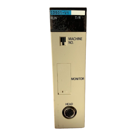
- Page 20 Components and Indicators Section 1-3 Components and Indicators Although similar in appearance, note that the C200H-IDS01-V1 ID Sensor reads or writes data through a Read/Write Head and the C200H-IDS21 reads or writes data through a Read/Write Antenna. C200H-IDS01-V1 Front Panel IDS01-V1 Indicators Unit number switch...
Need help?
Do you have a question about the SYSMAC C200H-IDS01-V1 and is the answer not in the manual?
Questions and answers