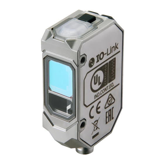
Omron E3AS-HL500MT 2M Instruction Sheet

Omron E3AS-HL500MT 2M Instruction Sheet

Cmos laser sensor

Advertisement

E3AS-HL150□/HL500□
Model
CMOS Laser Sensor
INSTRUCTION SHEET
Thank you for selecting OMRON product. This sheet primarily describes precautions 
required in installing and operating the product.
Before operating the product, read the sheet thoroughly to acquire sufficient 
knowledge of the product. For your convenience, keep the sheet at your disposal.
TRACEABILITY INFORMATION:
Importer in EU:
Manufacturer:
  Omron Europe B.V.
  Omron Corporation,
  Wegalaan 67-69
  Shiokoji Horikawa, Shimogyo-ku,
  NL-2132 JD Hoofddorp,
  Kyoto 600-8530 JAPAN
  The Netherlands
The following notice applies only to products that carry the CE mark.
Notice:
In a residential environment, this product may cause radio interference,
in which case the user may be required to take adequate measures.
©  OMRON Corporation  
2020
  All Rights Reserved. 
PRECAUTIONS ON SAFETY
●Meaning of Signal Words
Indicates a potentially hazardous situation which, if not avoided, 
WARNING
will result in minor or moderate injury, or may result in serious injury 
or death. Additionally there may be significant property damage.
Indicates a potentially hazardous situation which, if not avoided, 
CAUTION
may result in minor or moderate injury or in property damage.
WARNING
This product is not designed or rated for ensuring safety of persons 
either directly or indirectly. Do not use it for such purpose.
Do not use the product with voltage in excess of the rated voltage.
Excess voltage may result in malfunction or fire.
CAUTION
Its component may be damaged and/or degree of protection may be degraded. 
Please do not apply high pressure water intensively at one place during cleaning.
To safely use laser products
WARNING
Looking into the Outgoing light continuously may cause visual impairment.
Do not look directly into the Outgoing light.
Caution-Use of controls or adjustments or performance of procedures other 
than those specified herein may result in hazardous radiation exposure
Attention-Lʼutilisation des commandes ou réglages ou lʼexécution des 
procédures autres que celles spécifiées dans les présentes exigences 
peuvent étre la cause dʼune exposition à un rayonnement dangereux
Do not disassemble this product.Doing so may cause exposure to 
the built-in light source which can damage eyes and skin. Never 
disassemble it.
Laser safety measures for laser equipment are stipulated by the country of use. Follow 
the instructions described below categorized in four cases.
・ Usage in Japan
The JIS C6802:2014 standard stipulates the safety precautions that users must take 
according to the class of the laser product. This product is classified into class 1 defined 
by this standard.
・ Usage in U.S.
This product is subjected to the U.S. FDA (Food and Drug Administration) laser 
regulations. This product is classified into Class 1 by the IEC 60825-1:2014 standard 
according to the regulations of Laser Notice No.56 of the FDA standard. This product is 
already reported to CDRH (Center for Devices and Radiological Health).
Accession Number: 1920014-001
When using a device equipped with the product in the U.S., attach an FDA certification 
label near the sensor mounted on customer equipment.
FDA certification label
・ Usage in China
This product is classified into Class 2 by the GB7247.1:2012(IEC60825-1:2007) standard.
When using a device equipped with the product in China, attach a Warning label near 
the sensor mounted on customer equipment.
Warning label
Center of laser projection
・ Usage in countries other than U.S. and China
This product is classified into Class 1 by the IEC60825-1:2014/EN60825-1:2014+A11:2021 
standard.
* 5 6 3 0 5 3 9 - 9 D *
1
Precautions for Safe Use
Please observe the following precautions for safe use of the products.
•Do not reverse connection of DC power supply polarity. Do not connect 
to AC power supply.
•Do not short-circuit the load.
•Never use this product with AC power supply. Otherwise it may 
explode.
•The maximum power supply voltage is 30 VDC. Before turning on the 
product's power, make sure that the supply voltage does not exceed 
the maximum power supply voltage.
•Do not use the product in environments where flammable or explosive 
gases are present.
•Please assess the safety beforehand when using the product in 
chemicals and/or oil environments.
•Do not remodel the product.
•Do not touch the metal surface with your bare hands when the 
temperature is low. Touching the surface may result in a cold burn.
•Burn injury may occur. The product surface temperature rises 
depending on application conditions, such as the ambient temperature 
and the power supply voltage. Attention must be paid during 
operation or cleaning.
Precautions for Correct Use
•Do not hit the product using a hammer for installation.
•The product must be installed with the specified torque or less.
 For M8 connector and Pre-wired M8 connector, the proper tightening 
torque is from 0.3 to 0.4 N ・ m.
 In case of M12 Pre-wired smartclick connector, manually tighten the 
connector.
•Tightening torque for the mounting hole is 0.6 N ・ m or less (M3 screw).
•Do not use the product in ambient atmosphere or environment exceeding 
the rating.
•Output pulses may be generated when the power is turned off. It is 
recommended to turn off the power of the load or load line first.
•The extension of the cord under the standard I/O mode should be 100 m 
or less.Under the IO-Link mode, the length should be 20 m or less.
•Do not pull the cord too strongly.
•Be sure to turn off the power supply when connecting or disconnecting 
the cable.
•Wait for at least 600 ms after turning on the product's power.
•The product is rated as IP67 but please avoid using the product 
underwater, under rain, and outdoors.
•If the Sensor wiring is placed in the same conduits or ducts as high-voltage 
or high-power lines, inductive noise may cause malfunction or damage. 
Wire the cables separately or use a shielded cable.
•Do not use the product in direct sunlight.
•Do not use the product where humidity is high and dew condensation 
may occur.
•Do not use the product where corrosive gases may exist.
•Use a key lock to prevent malfunction if high-pressure wash water or other 
substances come into contact with the button.
• Do not apply high-pressure washing water directly to the sensor's light 
emitting / receiving surface from a short distance. As the antifouling 
feature may be impaired, keep a sufficient distance from the light emitting 
/ receiving surface.
•Do not use the product at a location subject to shock or vibration.
•To use a commercially available switching regulator, FG (frame ground) 
must be grounded.
•This product cannot be used as a detection device for human body 
protection.
•Do not use organic solvents (e.g. paint thinner and alcohol) for cleaning. 
Otherwise optical properties and protective structure may deteriorate.
•Be sure to check the influence caused by surrounding environments such 
as background objects and/or LED lighting before using the product.
•Do not exceed 100,000 writing operations of the EEPROM (non-volatile 
memory). Setting information is written to the EEPROM when a threshold 
value change, teaching, or zero reset is executed.
Dispose in accordance with applicable regulations.
Package contents
Instruction sheet  (this sheet) , Compliance sheet, Index list (attached for 
IO-Link type only), FDA certification label, Warning label

Advertisement

Table of Contents
loading
Need help?

Need help?

Do you have a question about the E3AS-HL500MT 2M and is the answer not in the manual?

Questions and answers

Summary of Contents for Omron E3AS-HL500MT 2M

  • Page 1 •Burn injury may occur. The product surface temperature rises    NL-2132 JD Hoofddorp,   Kyoto 600-8530 JAPAN depending on application conditions, such as the ambient temperature    The Netherlands and the power supply voltage. Attention must be paid during  The following notice applies only to products that carry the CE mark. operation or cleaning. Notice: In a residential environment, this product may cause radio interference, in which case the user may be required to take adequate measures. Precautions for Correct Use ©  OMRON Corporation   2020   All Rights Reserved.  •Do not hit the product using a hammer for installation. * 5 6 3 0 5 3 9 - 9 D * •The product must be installed with the specified torque or less.  For M8 connector and Pre-wired M8 connector, the proper tightening  PRECAUTIONS ON SAFETY torque is from 0.3 to 0.4 N ・ m.  In case of M12 Pre-wired smartclick connector, manually tighten the  ●Meaning of Signal Words connector. •Tightening torque for the mounting hole is 0.6 N ・ m or less (M3 screw).
  • Page 2: Installation

    ■Using Pin2 (white wire) as external input "3-3 External Input" (             p age 3). Installation Model Method Input/Output circuit diagram Mounting of the Sensor Brown ① <Size of installation holes (Unit: mm)> Load Black 100mA or less OUT1 ④ E3AS- White □□N□ EXTIN ②  28.7  10 to 30 VDC External Input Blue Reference  ③  3  surface Brown ① Black External Input PNP/COM□ OUT1 ④ White E3AS- Standard I/O  EXTIN ②...
  • Page 3 Output2 Function Settings The function assigned to output 2 (Pin2, white wire) can be selected. Operation/Display Lookup Table The output 2 fanction can be selected from the menu setting section. Output 2 function in”6 Detailed Settings”(   page8) ■Name and function of each part Menu display Function Operation indicator  [TEACH] button (orange) ・ Executes various Out1 Invert Output 1 Invert teaching. Out2 Single Output 2  [Single] [UP] button Input External Input ・ Changes the  threshold value or set  Error Error Output *1 Power & Communication  value. indicator (green) *1. Output 2 turns ON when a system error or load short circuit error  [DOWN] button occurs. ・ Changes the  threshold value or set  External Input value.
  • Page 4: Output Mode

    Output Mode The mode of output 1 (Pin4, black wire) can be selected.  An output mode can be selected from the menu setting screen. Output Mode in "6 Detailed Settings" (   page 8) Output mode is selected automatically by executing each teaching."4 Teaching" (   page 5 to 6 ) Function Output mode Relations with teaching Reference Description Sensing method *1 Single Point 2-point/Background teaching The output is inverted when the detected value falls  "4-1 Basic Teaching" (   page 5) below the threshold value (SP1). Background teaching [Single]   "4-1 Basic Teaching" (   page 5) Window BGS Object teaching "4-2 Advanced Teaching"  The output is inverted when the detected value is  (   page 6) between the Far side (SP1) and Near side (SP2)  [Window BGS]   threshold values. Background reference  Window FGS "4-1 Basic Teaching"  (   page 5) teaching (normal) [Window FGS]  ...
  • Page 5 ■Background Teaching [Teach 3sec (Background)] Teaching Use to detect an object closer than the background. ・ For output 1 (Pin4, black wire), 5 types of teaching are usable by button  ・ This can be executed if setting [Background] when executing Teaching  operations. Selection in "6 Detailed Settings"(   page 9) ・ For output 2 (Pin2, white wire), teaching is not usable by button operations.  ([Background] is the factory setting.) However, output 2 teaching can be executed by the communication  commands of IO-Link (only 2-point teaching and background teaching is  1. Press and hold the         button without any objects (longer than 1s and shorter than 5s).  usable). TEACH Release the button when [Background Teach] is displayed on the display ■Teaching operation lookup table Item Operation Press Quickly Press Quickly 2-point teaching        TEACH TEACH Item Operation Teaching Selection [Teach 3sec] ・ [Single] is selected automatically as the output mode. Background teaching Press&Hold [Background] *1 Object teaching [Object] TEACH ●Threshold setting after teaching is completed Bg. Ref. Teaching Selection Item Operation [Ref. Teach]...
  • Page 6 Note 1. When background reference teaching (sensitive) has been executed, use the  Advanced Teaching sensor at least 10 minutes after turning ON the power. Note 2. When using the sensor to detect a transparent object, be sure to check  ■Object Teaching [Teach 3sec (Object)] operation in advance. Use for teaching with an object. Note 3. When response time has been changed, execute teaching again. ・ This can be executed if [Object] is set when Teaching Selection in "6  The ABT function which controls the influence of the moderate variation of the  Detailed Settings" (    page 9) is executed. ([Background] is the  background is enabled automatically. The memorized background information is  corrected automatically.  In ABT function, correction time can be selected from four  factory setting.) options (OFF / 0.3sec / 1sec / 3min). "6-11 ABT Function" (   page 11) ●If detection is not stable when background reference teaching (sensitive) is executed: 1. Press and hold the         busson with an object (longer than 1s and shorter than 5s).  TEACH Possible causes are as follows. Check the installation state and execute teaching again. Release the button when [Object Teach] is displayed on the display Factor Countermeasure The distance between the sensor and  Check the installation condition. the background varies by more than  5% of the detection distance. The reflected light from the  Keep the distance between the sensor  background does not have sufficient  and the background close. intensity. The specular reflection light from the  Tilt the sensor to prevent specular  ・ [Window BGS] is selected automatically as the output mode. background enters. reflection light from entering (10°  or  more). The installation shown below is ...
  • Page 7: Useful Functions

    ●Key lock cancel Threshold Value Manual Operations The threshold value can be adjusted using the [UP] button and the  [DOWN] button. The threshold value increases. Quick adjustment is usable  Press simultaneously for 3s or more TEACH DOWN by pressing and holding  The threshold value decreases. the button. DOWN Setting completed ■When output mode is [Single] The unlocked icon is displayed on the main screen. The threshold values of output 1 and output 2 can be adjusted. Threshold value Model Factory setting Setting range The screen returns to the main screen after the  Output1 Output2 elapse of a certain time. HL500□ -600〜600 Initialization HL150□ -160.0〜160.0 100.0 100.0 Settings are initialized and returned to the factory settings. Initialization in "6 Detailed Settings" (   page 8) Zero Reset Short press for 1s or less The detection value when zero reset is executed is set to [0]. DOWN ●Zero reset execution  Output 1  Output 2*1 Threshold value ...
  • Page 8: Detailed Settings

    Detailed Settings Main  Screen This chart shows the transition of the menu setting screen. [UP] Left shift / Numerical value + 3sec [DOWN] Right shift / Numerical value - DOWN DOWN Response Time Response   6-1(page10) TEACH 50 ms 50 ms 10 ms 1.5 ms DOWN Out1 Mode Output 1 Mode TEACH Single Single Window BGS Window FGS Dist + Int *1   3-4(page4) DOWN *1. Displayed only when background reference teaching (sensitive) is executed  Out1 Logic Output 1 Logic (output 1 mode = Dist + Int). TEACH N.O. N.O. N.C.   6-2(page10) DOWN Output 1  Timer Mode1 Timer Mode TEACH Off...
  • Page 9 Display Reverse Disp. Reverse   6-5(10page) TEACH Off Off DOWN Brightness Display Brightness TEACH Normal Normal Dark   6-6(10page) DOWN Zero Memory Zero Reset   TEACH Memory*3 Off Off *3. Not displayed only when background reference teaching (sensitive) is executed    5-3(7page) (output 1 mode = Dist + Int). DOWN Keep Func. Keep Function*3 TEACH Off Off   6-7(10page) DOWN Mutual Interference  Interference Prevention TEACH Channel 1 Channel 1 Channel 2 Channel 3 Channel 4   6-8(10page) DOWN...
  • Page 10 Response Time Display Brightness Response time can be changed. Description Display brightness Detection becomes more stable as increasing response time. Normal The brightness of the OLED display decreases after not operated  for a certain time (60s). Output 1 Mode Dark The OLED display is turned OFF perfectly after not operated for a  certain time (15s). The output logic (N.O. or N.C.) of output 1 or output 2 can be switched. The logic of output 2 can be changed only when the output 2 function is  Note 1. Display's luminance decreases as the sensor is used for a long period. set to [Out2 Single]. Keep Function Timer Mode The output when receiving light intensity is not sufficient or detection  The timer operation of the output can be set. has not been determined yet can be set. Timer mode Description on function Output Keep Off The timer function is not used. Function N.O. setting N.C. setting On Delay Off Output ON Output ON is retarded after the object is detected. Output OFF The detected value directly before the sensor judges as  Off delay Output ON is held if the detection time is too short for PLC to detect the object. impossible to detect is saved and output. One shot Output is held for a certain period of time even if the object size varies.
  • Page 11: Troubleshooting

    6-11 ABT Function (Automatic-Background-Tracking) Troubleshooting The ABT function is enabled only when background reference teaching  ■Error Display (sensitive) is executed. Error name /  Indicator This function corrects variation of the detected value when background  Error details Possible causes is detected (coincidence between distance and intensity) and keep the  display Green Orange detected value at 100. The laser diode  Restart the  Laser failure error The number of times of maintenance is reduced by automatically  might have  sensor (turn the  correcting the variation of the detected value due to stain on the  been  power off and  sensor's receiving surface or the background object. deteriorated. on again). If the error  The correction time can be selected from four options (OFF / 0.3sec /  Orange and green  remains,  1sec / 3min). indicators show quick  An error  System error replace the  flashing alternately occurred in the  sensor. (at 0.2s intervals) (Precautions) system.
  • Page 12: Ratings And Specifications

    ■Model standard Suitability for Use OMRON Corporation shall not be responsible for conformity with any standards, codes or E 3 A S-H L □ □ □ M □ □    □   □ regulations which apply to the combination of the Product in the Buyer’s application or use of the Product.

Table of Contents