Advertisement
Photoelectric Sensors with Separate Digital Amplifiers (Laser-type Amplifier Units)
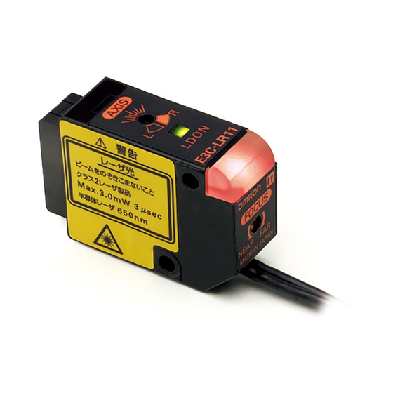
E3C-LDA Series
• All seven laser types provide ample
long distance, for the Diffuse Reflective
Model 1.000 mm and for Retroreflec-
tive Models up to 7.000 mm.
• Coaxial Retroreflective Models provide
detection performance equivalent to
through-beam sensors, simplifying
Sensor installation.
• Industry-first variable focal point and
optical axis alignment mechanisms.
Optimize for workpieces and improve
inspection quality.
• Drive the laser with an Amplifier the
same size as a Digital Fiber Amplifier.
Ordering Information
Sensor Heads
Sensing method
Diffuse reflective
Spot (variable)
Coaxial retroreflec-
tive
Spot (2.0-mm fixed
Note: Select a reflector (sold separately) according to the application.
Amplifier Units
Amplifier Units with Cables
Item
Twin-output
models
Advanced
models
External-input
models
Amplifier Units with Connectors
Item
Twin-output
models
Advanced
models
External-input
models
E3C-LDA Series
Focus
Model number
Spot
E3C-LD11
Line
E3C-LD21
Area
E3C-LD31
E3C-LR11 (See
note.)
E3C-LR12 (See
dia.)
note.)
Appearance
Appearance
Mounting a Beam Unit (sold separately) allows the use of line and
This model number is for the set consisting of the E39-P11 mount-
ed to the E3C-LD11.
This model number is for the set consisting of the E39-P21 mount-
ed to the E3C-LD11.
Mounting a Beam Unit (sold separately) allows the use of line and
Functions
Area output, self-diagno-
sis, differential operation
Remote setting, counter,
differential operation
Functions
Area output, self-diagno-
sis, differential operation
Remote setting, counter,
differential operation
Remarks
area beams.
area beams.
---
Model
NPN output
PNP output
E3C-LDA11
E3C-LDA41
E3C-LDA21
E3C-LDA51
Model
NPN output
PNP output
E3C-LDA6
E3C-LDA8
E3C-LDA7
E3C-LDA9
A-455
Advertisement
Table of Contents

Related Manuals for Omron E3C-LDA - DATASHEET 3


Summary of Contents for Omron E3C-LDA - DATASHEET 3
-
Page 1: Ordering Information
Ordering Information Sensor Heads Sensing method Focus Model number Remarks Mounting a Beam Unit (sold separately) allows the use of line and Spot E3C-LD11 area beams. This model number is for the set consisting of the E39-P11 mount- Diffuse reflective... -
Page 2: Specifications
3. The beam radius is the value for the middle measurement distance and indicates a typical value for the middle sensing distance. The radius is defined by light intensity of 1/e (13.5%) of the central light intensity. - Page 3 Materials Cover Polycarbonate *1: Communications are disabled if super-high-speed mode is selected, and the mutual interference prevention function and the communications function for the Mobile Console will not function. *2: The preset counter is available only with advanced, external-input models.
-
Page 4: Basic Operating Information
Select for actual detection operation or to set the following: Manual adjust- ment of thresholds, power adjustment, zero reset, or key lock. Key Operations The operation keys are used to switch the displays and set detection conditions. The functions of the keys depend on the current mode. Function... - Page 5 (default: 2,000). Before tuning ON the power, always secure the detection object and Head and be sure that the incident light level is stable. The power tuning target value can be changed. Refer to Detailed Settings.
- Page 6 Teaching for a Through-beam or Retroflective Sensor Head is performed without a workpiece. A value about 6% less than the incident light level is set as the threshold value. This method is ideal to stably detect very small differences in light level.
- Page 7 Teaching can be performed twice, once with and once without a workpiece, and the value between the two measured values is set as the threshold. If DIFF (differential operation) is set for the detection method, the threshold value will be set to half of the difference be- tween the two measured values.
- Page 8 Setting Erros An error has occurred if any of the following is display when the UP or DOWN key is pressed without a workpiece. Do one of the following and then repeat the operation Flashes twice • Adjust the Head to decrease the incident light level.
-
Page 9: Detailed Settings
Detailed Settings The following functions can be set in SET mode. The default settings are shown in the transition boxes between functions.For Twin- output Models, all settings except for the operation mode and timer settings are the same for both channels. - Page 10 1 to 5 s 1-s increments The information displayed in RUN mode can be selected. When going to SET mode, this setting will be ignored and 3. Display Switch the incident light level and threshold value will be displayed. The incident light level...
- Page 11 321D (Twin-output Models Only) 7. Twin Outputs The function of the output for channel 2 can be selected. This setting is not value if DIFF (differential operation) is set for the detection method. (The output for channel 2 is always an alarm output for differential operation.) Output for each channel.
-
Page 12: Convenient Functions
Convenient Functions Zeroing the Main Display The incident light level displayed on the main display can be zeroed. The threshold displayed in the sub-display is shifted by an amount corresponding to the amount the incident light level was changed. Confirm that the MODE key setting is 0RST (zero reset) in advance. PTUN (power tuning) is the default setting. Refer to Detailed Settings. - Page 13 “LOC” will flash twice on the display to indicate that key operations have been disabled. Initializing Settings This procedure can be used to return all the settings to the original default values. Setting Method Switch to SET mode. Press the UP or DOWN key for at least 3 seconds.
-
Page 14: Installing The Amplifier Unit
Mounting Units Catch the hook on the Sensor Head connector end of the Unit on the DIN Track and then press down on the other end of the Unit until it locks into place. Always attach the Sensor Head connector end first. - Page 15 Two, 3.2-dia. 27.7 mounting holes R 4.8 18.8 Two, R 2.6 Connector × 2 conductors Round vinyl-clad cable, 1.8 dia. (cross-sectional area of conductor: 0.15 mm Standard length: 2 m Reflector Amplifier Unit E39-R12/-R14 E39-R13 E3C-LDA11 24 17.2 45 37...
- Page 16 ALL DIMENSIONS SHOWN ARE IN MILLIMETERS. To convert millimeters into inches, multiply by 0.03937. To convert grams into ounces, multiply by 0.03527. Cat. No. E13E-EN-01 In the interest of product improvement, specifications are subject to change without notice. A-470 Advanced Photoelectric Sensors...
Need help?
Do you have a question about the E3C-LDA - DATASHEET 3 and is the answer not in the manual?
Questions and answers