
Related Manuals for Omron V600-CA1A


Summary of Contents for Omron V600-CA1A
- Page 1 Cat.No. Z127–E1–1 V600 RFID System R/W Heads and SRAM Data Carriers OPERATION MANUAL...
- Page 2 V600 RFID System R/W Heads and SRAM Data Carriers Operation Manual Produced August 1998...
- Page 3 OMRON. No patent liability is assumed with respect to the use of the information contained herein. Moreover, because OMRON is constantly striving to improve its high-quality products, the information contained in this manual is subject to change without notice.
-
Page 4: Table Of Contents
TABLE OF CONTENTS SECTION 1 Features and System Configuration ....Features ............. . . System Configuration . - Page 5 About this Manual: This manual describes the installation and operation of the V600-series Read/Write Heads and battery- powered SRAM Data Carriers, and includes the sections described below. Please read this manual carefully and be sure you understand the information provided before attempting to install and operate the Read/Write Heads and Data Carriers.
-
Page 6: Features And System Configuration
SECTION 1 Features and System Configuration This section provides a general introduction to the V600 RFID System, including the V600-series Read/Write (R/W) Heads and Data Carriers. The V600 RFID System utilizes non-contact data transfer in which data is transmitted electromagnetically without physical contact between the devices. -
Page 7: Features
Section Features Features The V600 RFID System offers powerful support to the automation of large-scale distributed control systems and multi-model small-scale production systems by means of contactless data communication. Contactless Data Data is transmitted between the Data Carrier (DC) and Read/Write (R/W) Head Transfer electromagnetically in both directions, without physical contact between the two devices. -
Page 8: System Configuration
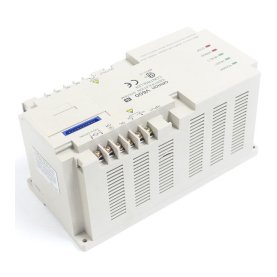
A V600 RFID System is made up of ID Controllers, R/W Heads, and DCs. A sys- tem can be assembled to suit almost any situation with different arrangements of these components. ID Controllers and ID Sensor Units V600-CA1A/CA2A V600-CA8A/CA9A V600-CF1A V600-CB-S... -
Page 9: Specifications
SECTION 2 Specifications This section provides Read/Write (R/W) Head and Data Carrier (DC) specifications. R/W Heads ............. 2-1-1 Specifications and Outer Dimensions . -
Page 10: R/W Heads
Section R/W Heads R/W Heads 2-1-1 Specifications and Outer Dimensions V600-H07/V600-H11 Model Item V600-H07 V600-H11 Operating frequency 530 kHz Operating temperature –25°C to 70°C –10°C to 60°C Storage temperature –40°C to 85°C –25°C to 75°C Operating humidity 35% to 95% RH Insulation resistance 50 MΩ... - Page 11 Section R/W Heads V600-H11 Vinyl-insulated Mounting holes Four, R1 round cord (6 dia) Two, R5 (Two, 4.5 dia.) Connector Bushing 14.7 dia. LED indicators Power supply (green) Communications (orange) Case material ABS resin Fill resin Epoxy resin Cable PVC (oil-resistant)
-
Page 12: Data Carriers
Section Data Carriers Data Carriers 2-2-1 Specifications and Outer Dimensions V600-D8KR12/13/04 Item Model V600-D8KR12 V600-D8KR13 V600-D8KR04 Memory capacity 8K bytes Memory type SRAM (static random access memory) Battery service life Refer to the graphs in 2-3 Data Carrier Battery Service Life. Number of data read/write No limit (up to the extent of the battery service life) conversions... - Page 13 Section Data Carriers WARNING The SRAM-type Data Carrier has a built-in lithium battery which can combust or explode if mishandled. Do not disassemble the Data Carrier, or subject it to high pressure or high temperatures (of 100°C or more), or dispose of it by incineration.
-
Page 14: Memory Map
Section Data Carriers 2-2-2 Memory Map The Data Carrier (DC) has a memory area of up to 8K bytes. Each address of the memory area specifies one byte. A single byte of data can be written to one address. Address Data 0000 Production date area... - Page 15 Section Data Carriers When Executing the Address Write Protect Function 0002 YES/ Leftmost two digits of beginning address 0003 Rightmost two digits of beginning address 0004 Leftmost two digits of ending address 0005 Rightmost two digits of ending address The region specified by the beginning and ending addresses will be protected when the write protect control bit (leftmost bit of address 0002 ) is ON, as shown in the following table.
-
Page 16: Data Carrier Battery Service Life
Section Data Carrier Battery Service Life Address É É É É É 0000 0006 É É É É É Ending address É É É É É Beginning address 1FFF É É É É É Canceling Write Protection To cancel write protection, turn OFF the leftmost bit of address 0002 . - Page 17 Section Data Carrier Battery Service Life With a V600-D8KR04 DC at 55°C (131°F), for example, 200 bytes of data can be accessed 3,000 times a day for 8 years or 6,500 times a day for 5 years. With a V600-D8KR12 DC at 55°C (131°F), 40 bytes of data can be accessed 2,000 times a day for 8 years or 4,500 times a day for 5 years.
-
Page 18: Battery Service Life Expectancy Check
Section Data Carrier Battery Service Life 2-3-2 Battery Service Life Expectancy Check Checking Whether the Battery is Low Models With Built-in Battery (Except V600-D2KR16) 1, 2, 3... 1. Data Carrier battery checks are not performed automatically, only during times of special access. When a battery check is performed, a small current is passed through the DC’s internal circuitry. -
Page 19: Communications Specifications
SECTION 3 Communications Specifications This section provides specifications for communications. Transmission Range ............3-1-1 Transmission Range Specifications (Certified Performance) . -
Page 20: Transmission Range
Section Transmission Range Transmission Range 3-1-1 Transmission Range Specifications (Certified Performance) Transmission range (unit: mm, axis slip: ±10 mm) R/W Head Setting conditions V600-D8KR12 V600-D8KR13 V600-D8KR04 V600-D2KR16 V600-H07 Stationary Flush-mounted within metal 10 to 50 10 to 30 See page 28. Surface-mounted on metal 10 to 60 10 to 35... -
Page 21: Transmission Time
Section Transmission Time 3-1-2 Transmission Areas The following diagrams show representative examples of the communications areas. All measurement units are shown in mm. V600-D8KR12 and V600-H07 V600-D8KR12 and V600-H11 V600-D8KR13 and V600-H07 V600-D8KR13 and V600-H11 V600-D8KR04 and V600-H07 V600-D8KR04 and V600-H11 V600-D2KR16 and V600-H11 Note The mounting method is surface-mounted on metal in all cases. - Page 22 Turn-around time (TAT) TAT (Reference) The following diagrams show the TAT and lower-level transmission time for V600-CA1A, V600-CA2A, V600-CD1D-V2, and V600-CF1A Serial Interface ID Controllers. (The TAT for Parallel Interface ID Controllers and ID Sensor Units varies with the host’s software.)
-
Page 23: Data Carrier Speed
Section Data Carrier Speed Calculation Method (Reference) (Unit: ms) Read/Write Lower-level transmission time Read T = 1.8N + 48.4 Write T = 4.2N + 86.5 N: Number of bytes processed Data Carrier Speed The number of bytes that can be processed using the Auto Read and Auto Write commands depends on the speed of the DC. -
Page 24: Installation
SECTION 4 Installation This section describes the recommended installation methods for the R/W Heads and Data Carriers (DCs), and provides details on the battery’s service life expectancy and methods to check the battery’s condition. R/W Head Installation ........... . 4-1-1 Installation Method . -
Page 25: R/W Head Installation
Section R/W Head Installation R/W Head Installation 4-1-1 Installation Method V600-H07 R/W Head Use M4 screws and spring washers (in four places) for R/W Head installation. Tighten the screws to a torque of 0.7 to 1.2 NSm (approximately 7 to 12 kgfScm). There are no restrictions on the mounting direction or the direction of access to the DC, but if the R/W Head is to be installed near a device such as a conveyance belt, make sure there is no danger of the R/W Head being accidentally struck. -
Page 26: Effect Of Surrounding Metals
Section R/W Head Installation Note A mounting bracket is provided with the V600-H07. It is not necessary to use this bracket if a metal mounting plate larger than the 100×100 mm “footprint” of the R/W Head is used for installation. Mounting plate V600-H07 Mounting bracket... -
Page 27: Interference Between R/W Heads
Section R/W Head Installation gap between sides of the R/W Head and the metal casing is less than 50 mm, the read/write transmission range will be greatly diminished. (Unit: mm) 50 mm min. 30 mm max. 11 mm radius min. Metal casing 50 mm min. -
Page 28: Interference With Proximity Sensors
Section R/W Head Installation When facing the same direction, V600-H07 R/W Heads should be installed at least 550 mm apart (center to center) if RD/WT commands are used, and1,200 mm apart (center to center) if auto commands are used. 550 mm min. (1,200 mm min.) 650 mm min. -
Page 29: Data Carrier Installation
Section Data Carrier Installation perpendicular. When the two are facing each other, they should be at least 300 mm apart. Proximity sensor 300 mm min. Proximity sensor 400 mm min. V600-H07 400 mm min. Proximity sensor V600-H11 R/W Head As shown in the following diagrams, a V600-H11 R/W Head should be at least 100 mm from a proximity sensor regardless of whether the two are parallel, per- pendicular, or facing each other. - Page 30 Section Data Carrier Installation There are no restrictions on the mounting direction or the direction with respect to the R/W Heads. V600-D8KR12 V600-D8KR13 Two, M4 Two, M4 V600-D8KR04 Four, M4 Mounting in Metal Casing V600-D8KR12 Flush-mounted Surface-mounted É É É É É É É É É...
- Page 31 Section Data Carrier Installation When the V600-D8KR04 is flush-mounted in a metal casing, the transmission range varies according to the width of the gap (x) between the metal and the DC, as shown in the following graphs. When Combined With V600-H07 When Combined With V600-H11 ±...
- Page 32 Section Data Carrier Installation Mounting in a Metal The V600-D2KR16 can be either surface-mounted or flush-mounted in a metal Casing casing. If mounted as shown in the following diagrams, there will be no effect on the transmission range. Flush-mounted Surface-mounted 10 mm min.
-
Page 33: Chemical Resistance
SECTION 5 Chemical Resistance This section shows the chemicals that affect R/W Heads and Data Carriers. - Page 34 Section 5 Chemical Resistance R/W Heads and Data Carriers are constructed using both ABS resin and epoxy resin. Referring to the following charts, be sure to use only those chemicals that have no effect on the ABS or epoxy resins and avoid using those chemicals that do have an effect.
-
Page 35: A Accessories (Sold Separately)
Appendix A Accessories (Sold Separately) Item Specification Model Remarks Extension cable for R/W Heads V600-A45 The connectors are not waterproof. V600-A44 10 m V600-A40 20 m V600-A41 30 m V600-A42 Extension cable for R/W Heads V600-A56 The connectors are not waterproof. -
Page 36: B Discontinued Models And Replacements
For example, it is now possible to use a single data carrier in combination with the optimum read/write head for each process in an assembly line. • For OMRON as well, this change makes it easier to improve production schedules and quality control by integrat- ing product lines. - Page 37 Appendix B Discontinued Models and Replacements Materials Provided Here The following materials are provided in this appendix: • Information regarding model changes • Differences in specifications/performance between 500-kHz and 530-kHz models: • 530-kHz model specifications/performance • 500-kHz model specifications/performance • Combining 500-kHz and 530-kHz models: To some extent there are disadvantages such as a reduction in transmission range from combining 500-kHz and 530-kHz models.
- Page 38 Appendix B Discontinued Models and Replacements Model Changes Discontinued Models All 500-kHz models have been discontinued. R/W head: V600-H06 Data carriers: V600-D2KR01, V600-D8KR01, V600-D2KR02, V600-D8KR02, V600-D2KR03, V600-D8KR03 From now on, please use 530-kHz models. Replacement Models The following table shows the models that are replacing each of the discontinued models. Discontinued model (500 kHz) Replacement model (530 kHz) V600-H06...
- Page 39 Appendix B Discontinued Models and Replacements Specifications and Performance of 530-kHz Models Data Carriers V600-D8KR11 V600-D8KR12 V600-D8KR13 V600-D8KR04 Model Item (Standard type) (Compact type) (Thin type) (Mid-range type) V600-D8KR11 V600-D8KR12 V600-D8KR13 V600-D8K04 Memory capacity 8K bytes Memory type SRAM (static random access memory) Transmission (Refer to transmission range specifications on following page.) range...
- Page 40 Appendix B Discontinued Models and Replacements R/W Heads V600-H11 Model Item V600-H12 V600-H11 V600-H12 Operating frequency 530 kHz Operating temperature –10°C to 60°C –25°C to 70°C Storage temperature –25°C to 70°C –40°C to 85°C Operating humidity 35% to 95% RH Storage humidity 35% to 95% RH Degree of protection...
- Page 41 Appendix B Discontinued Models and Replacements Transmission Range Specifications (Recommended Operating Area) When Combined With V600-H11 Model Item V600-D8KR11 V600-D8KR12 V600-D8KR13 V600-D8KR04 Range Refer to Graph Stationary Flush-mounted 10 to 50 mm 5 to 40 mm 10 to 30 mm A and the within metal transmission...
- Page 42 Appendix B Discontinued Models and Replacements Transmission Area Diagrams The following diagrams are representative examples. The unit of measurement used is mm. V600-D8KR11 and V600-H11 V600-D8KR12 and V600-H11 V600-D8KR13 and V600-H11 V600-D8KR04 and V600-H11 V600-D8KR11 and V600-H12 V600-D8KR12 and V600-H12 V600-D8KR13 and V600-H12 V600-D8KR04 and V600-H12 Graph A...
- Page 43 Appendix B Discontinued Models and Replacements Note All mounting conditions shown here are for metal back panel mounting. Specifications and Performance of 500-kHz Models Data Carrier V600-D2KR01, V600-D8KR01 V600-D2KR02, V600-D8KR02 V600-D2KR03, V600-D8KR03 Model Item V600-D2KR01 V600-D2KR02 V600-D2KR03 V600-D8KR01 V600-D8KR02 V600-D8KR03 Memory capacity 2K bytes/8K bytes Memory type...
- Page 44 Appendix B Discontinued Models and Replacements Transmission Range Specifications (Recommended Operating Area) When Combined With V600-H06 Model Item V600-D2KR01 V600-D2KR02 V600-D2KR03 V600-D8KR01 V600-D8KR02 V600-D8KR03 Range Stationary Flush-mounted within metal 10 to 35 mm 5 to 25 mm 10 to 35 mm Moving Surface-mounted on metal 15 to 45 mm...
- Page 45 Appendix B Discontinued Models and Replacements 1) 500-KhZ R/W Head Combined With 530-kHz DC • Combined With V600-H06 Model Item V600-D8KR11 V600-D8KR12 V600-D8KR13 V600-D8KR04 Range Refer to Graph Stationary Flush-mounted 10 to 35 mm 5 to 25 mm 10 to 30 mm A and the within metal transmission...
- Page 46 Appendix B Discontinued Models and Replacements • Combined With V600-H11 Model Item V600-D2KR01 V600-D2KR02 V600-D2KR03 V600-D8KR01 V600-D8KR02 V600-D8KR03 Range Stationary Flush-mounted within metal 5 to 25 mm 5 to 20 mm 5 to 20 mm Moving Surface-mounted on metal 5 to 30 mm 5 to 25 mm 5 to 25 mm Stationary...
- Page 47 Appendix B Discontinued Models and Replacements V600-DjKR01 and V600-H11 V600-DjKR02 and V600-H11 V600-DjKR03 and V600-H11 Note All mounting conditions shown here are for metal back panel mounting. Dimensions V600-H06/12 Power indicator (LED) Mounting holes (four, 4.5 dia.) Bushing Connector Cable (6 dia.; 8 conductors, 7/0.12 dia.;...
- Page 48 Appendix B Discontinued Models and Replacements Case material ABS resin Fill resin Epoxy resin Cable PVC (oil-resistant) V600-DjKR01 V600-DjKR02 V600-D8KR11 V600-D8KR12 Mounting holes Mounting holes (two, 4.5 dia.) (four, 4.5 dia.) V600-DjKR03 V600-DjKR04 V600-D8KR13 Mounting holes Mounting holes (two, 4.5 dia.) (four, 4.5 dia.) Case material ABS resin...
-
Page 49: C Other Series
Appendix C Other Series In England, R/W Heads and Data Carriers with a transmission frequency of 470 kHz must be used. Model: V600-H06-T (R/W Head) V600-D2KR01-T (Data Carrier) Except for the transmission frequency, the specifications of the above 470-kHz models are exactly the same as those of the V600-H06 and V600-D2KR01. -
Page 50: Revision History
Revision History A manual revision code appears as a suffix to the catalog number on the front cover of the manual. Cat. No. Z127-E1-1 Revision code The following table outlines the changes made to the manual during each revision. Page numbers refer to the previous version. - Page 51 Mouser Electronics Authorized Distributor Click to View Pricing, Inventory, Delivery & Lifecycle Information: Omron V600-H12 10M...
Need help?
Do you have a question about the V600-CA1A and is the answer not in the manual?
Questions and answers