Sign In
Upload
Manuals
Brands
Intel Manuals
Chassis
SR2500
Intel SR2500 Manuals
Manuals and User Guides for Intel SR2500. We have
3
Intel SR2500 manuals available for free PDF download: Manual, Spares/Parts List And Configuration Manual, Hardware Installation Manual
Intel SR2500 Manual (110 pages)
Server Chassis/Server System
Brand:
Intel
| Category:
Server
| Size: 1 MB
Table of Contents
Table of Contents
4
1 Product Overview
13
Chassis Views
13
Figure 1. Front View with Optional Bezel
13
Figure 2. Front View Without Bezel (Shown with Standard Control Panel Option)
13
Figure 3. Back View - (Shown with 1+1 Power Supply Configuration)
13
Chassis Dimensions
14
System Components
14
Figure 4. Major Chassis Components
14
Table 1. Chassis Dimensions
14
System Boards
15
Figure 5. Back Panel Feature Overview
15
Control Panel Options
16
Figure 6. Control Panel Modules
16
Figure 7. Standard Control Panel Overview
17
Figure 8. LCD Control Panel Overview
18
Hard Drive and Peripheral Bays
19
Power Sub-System
19
Figure 9. Front Panel Feature Overview
19
System Cooling
20
Chassis Security
20
1.10 Rack and Cabinet Mounting Options
20
1.11 Front Bezel Features
21
Figure 10. Optional Front Bezel
21
Figure 11. Front Bezel Supporting Standard Control Panel
21
Figure 12. Front Bezel Supporting Intel Local Control Panel
22
2 Power Sub-System
23
Mechanical Overview
23
Single Power Supply Module Population
24
Handle and Retention Mechanism
24
Hot-Swap Support
24
Figure 14. Power Supply Blank
24
Airflow
25
AC Power Cord Specification Requirements
25
Output Cable Harness
25
Table 2. Power Harness Cable Definitions
25
P1 - Server Board Power Connector
26
P2 - Processor Power Connector
26
Table 3. P1 Main Power Connector
26
Table 4. P2 Processor Power Connector
26
P3 - Power Signal Connector
27
P4 - Backplane Power Connector
27
P5 MID-Plane Power Connector
27
AC Input Requirements
27
Table 5. P3 Power Signal Connector
27
Table 6. P4 Hot Swap Backplane Power Connector
27
Table 7. P5 MID-Plane Power Connector
27
AC Input Voltage Specification
28
AC Line 5 VSB Holdup
28
AC Line Dropout / Holdup
28
Efficiency
28
Table 8. Efficiency
28
Table 9. AC Input Rating
28
AC Inrush
29
Protection Circuits
29
Over-Current Protection (OCP)
29
Over-Voltage Protection (OVP)
29
Table 10. Over-Current Protection Limits / 240VA Protection
29
Over-Temperature Protection (OTP)
30
2.10 DC Output Specification
30
Output Power / Currents
30
Standby Output / Standby Mode
30
Table 11. Over-Voltage Protection (OVP) Limits
30
2.11 Power Supply Status LED
31
Table 12. LED Indicators
31
3 Cooling Sub-System
32
Non-Redundant Fan Module
33
Figure 15. Non-Redundant Fan Module
33
Table 13 Nonredundant Cooling Zones
33
Figure 16. Non-Redundant Fan Header Assignments on MID-Plane
34
Table 14. Non-Redundant Fan Connector Pin Assingment
34
Redundant System Fan Module
35
Figure 17. Fan Module Assembly
35
Table 15. Nonredundant Fan Header Assignment
35
Table 16 Redundant Cooling Zones
35
Figure 18. Redudant Fan Header Assignments on MID-Plane
36
Table 17 Redundant Fan Connector Pin Assingment
36
Air Flow Support
37
Power Supply Zone
37
Full Height Riser Zone
37
Table 18 Redundant Fan Header Assignment
37
CPU / Memory / Low Profile PCI Zone
38
Drive Bay Population
38
Figure 19. CPU Air Duct with Air Baffle
38
Figure 20. Drive Blank
38
4 Platform Control
39
Overview
39
5 System Board Interconnects
40
MID-Plane
40
Figure 21. Passive MID-Plane Board
40
Figure 22. SAS/SAS RAID MID-Plane Board
41
Table 19. 120-Pin Server Board-To-MID-Plane Bridge Board Connector Pin-Out
41
Table 20. MID-Plane Fan Header Pin-Outs
43
Table 21. MID-Plane Power Connector Pin-Out
43
Table 22. MID-Plane-To-Backplane Card Edge Connector #1 Pin-Out
44
Table 23. MID-Plane-To-Backplane Card Edge Connector #2 Pin-Out
45
Table 24. Active MID-Plane SAS RAID Battery Backup Connector Pin-Out
46
Table 25. Passive MID-Plane SATA/SAS Connector Pin-Outs
46
Figure 22. Active SAS/SAS RAID Midplane 2 Board
47
Bridge Board
48
Hot-Swap SATA/SAS Backplane
48
Figure 23. Bridge Board
48
Figure 24. Hot-Swap SAS/SATA Backplane (Front Side View)
49
Figure 25. Hot-Swap SAS/SATA Backplane (Back Side View)
49
Table 26. 2X4 SAS/SATA Backplane Power Connector Pin-Out (J7L2)
50
Table 27. 1X7 6Th HDD / Tape Drive Option Power Connector Pin-Out (J2M1)
50
Table 28. 6Th HDD Option SATA/SAS I/O Connector Pin-Out (J4L1)
50
Table 29. 2X22 Slim-Line IDE Optical Drive Connector Pin-Out (J5N1)
50
Table 30. Slim-Line Optical Drive Slot Connector (J1A1)
51
Table 31. IDE Device Master/Slave Configuration Jumper (J6L1)
51
Table 32. I2C Connector (J6L3)
52
Table 33. Pcie X4 Slot Connector from MID-Plane (J4N1)
52
Table 34. Pcie* X4 Slot Connector from MID-Plane (J6N1)
53
Table 35. USB Floppy Drive Connector (J2A1)
53
Table 36. Intel Local Control Panel (LCP) Connector (J9A1)
54
Table 37. Control Panel Slot Connector (J9B1)
54
Table 38. SAS/SATA Hard Drive Connector Pin-Outs (J2C3, J2B1, J4C1, J4B1, J7C1)
55
6 Peripheral and Hard Drive Sub-System
56
Slimline Drive Bay
56
Figure 27. Slim-Line Optical Drive Assembly
56
Figure 28. 50-Pin Connector to Slimline Optical Device
57
Table 39. J1L1 50-Pin Connector to Slimline Optical Device
57
Hard Drive Bays
58
Hot-Swap Drive Trays
58
Figure 29. Hard Drive Tray Assembly
58
Optional Tape Drive or 6 Th Hard Drive Flex Bay
59
Figure 26. Optional
59
Figure 31. Optional Tape Drive (Front View)
59
MID-Plane Options
60
Passive MID-Plane
60
Figure 32. Passive MID-Plane Board
60
Active MID-Plane with SAS /SAS RAID Support
61
Active Midplane2 with SAS/SAS RAID Support
61
Figure 33. Active MID-Plane with SAS / SAS RAID Support
61
Figure 34. Architecture Overview
63
Hot-Swap SAS/SATA Backplane
64
SAS/SATA Backplane Layout
65
SAS/SATA Backplane Functional Architecture
67
Table 40. Hard Drive LED Function Definitions
68
Table 41. Hard Drive Activity LED Functionality
68
7 Standard Control Panel
69
Control Panel Buttons
69
Control Panel LED Indicators
70
Table 42. Control Button and Intrusion Switch Functions
70
Table 43. Control Panel LED Functions
71
Power / Sleep LED
72
System Status LED
72
Table 44. SSI Power LED Operation
72
Table 45. Control Panel LED Operation
72
Drive Activity LED
73
System Identification LED
73
Control Panel Connectors
74
Table 46. External USB Connectors (J1B1)
74
Table 47. Video Connector (J1A1)
74
Internal Control Panel Interconnect
75
Table 48. 64-Pin Control Panel Connector (J6B1)
76
8 Intel Local Control Panel
77
LED Functionality
78
Table 49. Control Panel LED Functions
78
Power / Sleep LED
79
System Status LED
79
Table 50. SSI Power LED Operation
79
Table 51. Control Panel LED Operation
79
Drive Activity LED
80
System Identification LED
80
Intel ® Local Control Panel Interconnects
81
Table 52. 50-Pin Control Panel Connector
81
Table 53. Internal USB Header
82
9 PCI Riser Cards and Assembly
83
Riser Card Options
84
PCI Riser Card Mechanical Drawings
85
10 Supported Intel
89
Server Boards
89
Intel ® Server Board S5000PAL / S5000XAL Feature Set
89
Processor Support
91
11 Environmental and Regulatory Specifications
92
11.1 System Level Environmental Limits
92
11.2 Serviceability and Availability
92
Table 54. System Environmental Limits Summary
92
11.3 Replacing the Back up Battery
93
11.4 Product Regulatory Compliance
94
11.5 Use of Specified Regulated Components
94
Table 55. Product Safety & Electromagnetic (EMC) Compliance
95
11.6 Electromagnetic Compatibility Notices
96
Usa
96
FCC Verification Statement
97
ICES-003 (Canada)
97
Europe (CE Declaration of Conformity)
97
Japan EMC Compatibility
97
BSMI (Taiwan)
98
RRL (Korea)
98
CNCA (CCC-China)
98
11.7 Product Ecology Compliance
99
11.8 Other Markings
101
Appendix A: Chassis Integration and Usage Tips
103
Appendix B: POST Code Diagnostic LED Decoder
104
Table 56: POST Progress Code LED Example
104
Table 57. Diagnostic LED POST Code Decoder
105
Appendix C: POST Error Beep Codes
108
Table 58. POST Error Beep Codes
108
Table 59. BMC Beep Codes
108
Glossary
109
Reference Documents
110
Advertisement
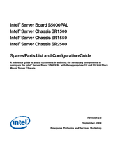
Intel SR2500 Spares/Parts List And Configuration Manual (27 pages)
Server Board & Server Chassis
Brand:
Intel
| Category:
Server
| Size: 0 MB
Table of Contents
Revision History
2
Table of Contents
4
1 Production Product Order Codes
5
Production Product Descriptions - Overview
5
Production Intel® Server Systems - (Integrated Skus)
5
Production Server Board Sku Options
9
Production Sr1500 (1U) Chassis Building Block Order Codes
9
Production SR1500 KDK Required Option #1 - Backplanes (Choose One)
10
Production SR1500 KDK Required Option #2 - Full-Height Riser (Choose One)
10
Production SR1500 KDK Required Option #3 - Control Panel (Choose One)
10
Production SR1500 KDK Optional Accessories & Spares
11
Production SR1550 (1U) Chassis Building Block Skus
12
Production SR1550 KDK Required Option #1 - Midplane (Choose One)
12
Production SR1550 KDK Required Option #2 - Full-Height Riser Card (Choose One)
13
Production SR1550 KDK Required Option #3 - Control Panel (Choose One)
13
Production SR1550 KDK Unique Optional Accessories & Spares
13
Production SR2500 (2U) Chassis Building Block Skus
14
Production SR2500 KDK Required Option #1 - Midplane (Choose One)
15
Production SR2500 KDK Required Option #2 - Full-Height Riser Card (Choose One)
15
Production SR2500 KDK Required Option #3 - Control Panel (Choose One)
15
Production SR2500 KDK Unique Optional Accessories & Spares
15
Production New Common Accessories and Spares
17
Production Re-Use Common Accessories & Spares
18
2 Intel ® Raid Controller Options
20
3 Vmware Vsphere* and Vcenter* Server Skus
21
4 Appendix 1: Boxed Processor Support
23
5 Appendix 2: Order Code Summary - Integrated Systems
24
6 Appendix 3: Order Code Summary - Building Blocks
26
Intel SR2500 Hardware Installation Manual (16 pages)
Basic Rail Kit for Server Chassis
Brand:
Intel
| Category:
Chassis
| Size: 0 MB
Table of Contents
Safety Information
3
Important Safety Instructions
3
Wichtige Sicherheitshinweise
3
Consignes de Sécurité
3
Instrucciones de Seguridad Importantes
3
Table of Contents
5
Rail Kit Installation Instructions
9
Before You Begin
9
Tools and Supplies Needed
9
Kit Content List (AXXBASRAIL13)
10
Figure 1. Rail Kit Components
10
Installation Instructions
11
Remove the Inner Rail from the Rail Assembly
11
Figure 2. Removing the Inner Rail from the Rail Assembly
11
Install Outer Rail Slides to Rack Posts
12
Figure 3. Installing the Outer Rail Slides to the Rack Posts
12
Attach Inner Rails to Server Chassis Sidewalls
13
Figure 4. Attaching the Inner Rails to the Server Chassis Sidewalls
13
Install the Server Chassis into the Rack
14
Figure 5. Installing the Server Chassis into the Rack
14
Figure 6. Installing the Server Chassis into the Rack
15
Advertisement
Advertisement
Related Products
Intel SR2300 - FRONT BEZEL BLK
Intel SR2600
Intel SR2625
Intel SR1425BK1 - Entry Server Platform
Intel SR1560SF - Server System - 0 MB RAM
Intel SR1500 - AXXMINIDIMM DDR-2 RAID Controller Cache Memory
Intel SR1425BK1-E
Intel SR1550
Intel SR1600
Intel SR1625
Intel Categories
Motherboard
Computer Hardware
Server
Desktop
Server Board
More Intel Manuals
Login
Sign In
OR
Sign in with Facebook
Sign in with Google
Upload manual
Upload from disk
Upload from URL