Moxa Technologies TN-5308-LV Installation Manual
Tn-5308 series toughnet layer 2 m12 unmanaged ethernet switches
Hide thumbs
Also See for TN-5308-LV:
- Installation manual (14 pages) ,
- Quick installation manual (12 pages)
Table of Contents

Related Manuals for Moxa Technologies TN-5308-LV


Summary of Contents for Moxa Technologies TN-5308-LV
- Page 1 Moxa ToughNet Switch TN-5308 Series Layer 2 M12 unmanaged Ethernet switches Hardware Installation Guide First Edition, May 2009 © 2009 Moxa Inc. All rights reserved. Reproduction without permission is prohibited. P/N: 1802053080010...
-
Page 2: Package Checklist
Overview The ToughNet TN-5308 series M12 unmanaged Ethernet switches are designed for industrial applications in harsh environments. The TN series switches use M12 connectors to ensure tight, robust connections, and guarantee reliable operation against environmental disturbances, such as vibration and shock. The TN-5308 series Ethernet switches provide 8 Fast Ethernet M12 ports, support IEEE 802.3/802.3u/802/3x with 10/100M, full/half-duplex, MDI/MDI-X auto-sensing, and provide an economical solution for your industrial Ethernet network. - Page 3 TN-5308-LV Panel Layouts Front Panel View Rear Panel View TP port’s 10/100 Mbps LED 10/100BaseT(X) port (female 4-pin shielded M12 connector with D coding) Port label Screw holes for panel mounting kit or DIN rail mounting kit (there are 3 holes: top middle, bottom left, and bottom right)
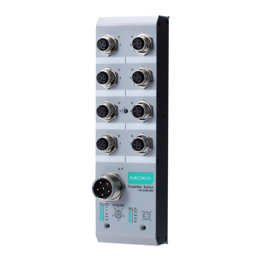
- Page 4 TN-5308-MV Panel Layouts Front Panel View Rear Panel View TP port’s 10/100 Mbps LED 10/100BaseT(X) port (female 4-pin shielded M12 connector with D coding) Port label Screw holes for panel mounting kit or DIN rail mounting kit (there are 3 holes: top middle, bottom left, and bottom right) Power input LED Power input port (male 5-pin shielded M23 connector with A coding)
-
Page 5: Mounting Dimensions (Unit = Mm)
Mounting Dimensions (unit = mm) TN-5308-LV Rear View Front View Side View DIN-Rail Mounting Kit TN-5308-MV Rear View Front View Side View DIN-Rail Mounting Kit — 4 —... -
Page 6: Panel/Wall Mounting
Panel/Wall Mounting Mounting the TN-5308-LV/MV on the wall requires 3 screws. Please use the 3 screws packed in the panel mounting kit. STEP 1: Prepare the 3 screw holes on the wall according to the positions of the 3 screw holes on the switch shown on the mounting dimension diagram. -
Page 7: Wiring Requirements
Wiring Requirements WARNING Turn the power off before disconnecting modules or wires. The correct power supply voltage is listed on the product label. Check the voltage of your power source to make sure you are using the correct voltage. Do NOT use a voltage greater than what is specified on the product label. -
Page 8: Connecting The Power Supply
Connecting the Power Supply The M12/M23 A-coded 5-pin male connector on the TN-5308-LV/MV front panel is used for the DC power input. You have to prepare a power cord with M12/M23 A-coded 5-pin female connector to connect the switch to the DC power input. -
Page 9: Connecting The Data Lines
Connecting the Data Lines 10/100BaseT(X) Ethernet Port Connection All TN-5308 models have 8 10/100BaseT(X) Ethernet ports (4-pin shielded M12 connectors with D coding). The 10/100TX ports located on the TN-5308’s front panel are used to connect to Ethernet-enabled devices. Most users configure these ports for Auto MDI/MDI-X mode, in which case the port’s pinouts are adjusted automatically depending on the type of Ethernet cable used (straight-through or cross-over), and the type of device (NIC-type... -
Page 10: Auto Mdi/Mdi-X Connection
M12 (4-pin, M) to M12 (4-pin, M) Straight-Trough Cable Wiring Straight-through Cable Wiring M12 (4-pin, M) to RJ45 (8-pin) Cross-Over Cable Wiring Cross-Over Cable Wiring M12 (4-pin, M) to RJ45 (8-pin) Straight-Trough Cable Wiring Straight-through Cable Wiring Auto MDI/MDI-X Connection The Auto MDI/MDI-X function allows users to connect TN-5308’s 10/100BaseTX ports to any kind of Ethernet device, without needing to pay attention to the type of Ethernet cable being used for the connection. -
Page 11: Dual Speed Functionality & Switching
Dual Speed Functionality & Switching The TN-5308’s 10/100 Mbps switched M12 ports auto negotiate with the connected device to use the fastest data transmission rate supported by both devices. All of Moxa’s ToughNet switches are plug-and-play devices, so that software configuration is not required. The half/full duplex mode for the switched M12 ports is user dependent and changes (by auto-negotiation) to full or half duplex, depending on which transmission speed is supported by the attached device. -
Page 12: Auto-Negotiation And Speed Sensing
Protection Physical Characteristics Housing Metal, IP40 protection Dimensions (W × H × D) TN-5308-LV: 60 x 216.6 x 36.1 mm (2.36 x 8.53 x 1.42 in) TN-5308-MV: 60 x 216.6 x 53.7 mm (2.36 x 8.53 x 2.11 in) — 11 —... - Page 13 Weight TN-5308-LV: 485 g TN-5308-MV: 685 g Installation Panel mounting, DIN-Rail mounting (with optional kit) Environmental Limits Operating Temperature Standard Models: 0 to 60°C (32 to 140°F) Wide Temp. Models: -40 to 75°C (-40 to 167°F) Storage Temperature -40 to 85°C (-40 to 185°F)
Need help?
Do you have a question about the TN-5308-LV and is the answer not in the manual?
Questions and answers