Table of Contents

Subscribe to Our Youtube Channel
Related Manuals for Moxa Technologies ToughNet TN-5300A Series


Summary of Contents for Moxa Technologies ToughNet TN-5300A Series
- Page 1 TN-5300A Series Quick Installation Guide Moxa ToughNet Unmanaged Switch Version 1.1, January 2024 Technical Support Contact Information www.moxa.com/support 2024 Moxa Inc. All rights reserved. P/N: 1802053050031 *1802053050031*...
-
Page 2: Package Checklist
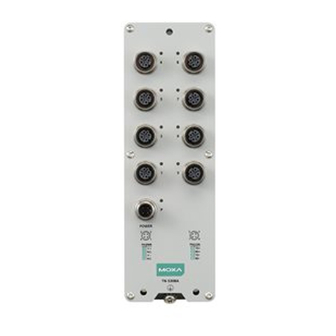
Overview The ToughNet TN-5300A Series M12 unmanaged Ethernet switches are designed for industrial applications in harsh environments. The TN- 5300A Series switches use M12 connectors to ensure tight, robust connections, and guarantee reliable resistance against environmental disturbances, such as vibration and shock. The TN-5300A Series... -
Page 3: Panel Layouts
ATTENTION (For PoE Models) For safety reasons, the product is considered not likely to require connection to an Ethernet network with outside plant routing. ATTENTION Exposed connectors must be tightly covered with protective caps (an optional accessory) when not in use to ensure IP67- rated protection. - Page 4 Mounting Dimensions (unit = mm) TN-5305A Models - 4 -...
- Page 5 TN-5308A Non-PoE Models - 5 -...
- Page 6 TN-5308A PoE Models - 6 -...
-
Page 7: Cooling Requirements
Cooling Requirements The thermal design of this product uses convection cooling. Make sure the ambient temperature is within the device’s operating temperature range and ensure the airflow around the product is not obstructed. The recommended minimum ventilation space for each side is listed below: Top and bottom: 50 mm Sides: 50 mm Front: 50 mm... -
Page 8: Wiring Requirements
Installation STEP 1: Align the wall-mounting holes on the back of the ToughNet device with the DIN-rail kit (marked A, B, C on the diagram). Tighten the screws (non-PoE models: M4 x P 0.7, 30 mm length; PoE models: M4 x P 0.7, 40 mm length) with a torque of 5 kgf-cm to secure the DIN-rail kit to the device. -
Page 9: Connecting The Power Supplies
perpendicular at the intersection point. NOTE: Do not run signal or communications wiring and power wiring through the same wire conduit. To avoid interference, wires with different signal characteristics should be routed separately. • You can use the type of signal transmitted through a wire to determine which wires should be kept separate. -
Page 10: Connecting The Data Lines
ATTENTION Do not power on the TN-5300A Series before connecting the M12 power connector. NOTE The suggested power cable is M12(FF4P)/Open-BK-100-IP68. The suggested plastic shell connector is M12-5P-IP68. The suggested metal shell connector is M12A-5PFF-IP67-HTG (5- pin). The suggested cord diameter is AWG 22 or larger. The cord dimensions depend on the choice of pin number and M12 coded type. -
Page 11: Led Indicators
Pinouts for the 10/100BaseT(X) Ports PoE Pin-out D-coded Pin 1, 3 (TD+, TD-) Pin 2, 4 (RD+, RD-) STEP 1: Plug the cable connector into the Ethernet port. Shielded cable is recommended. STEP 2: Screw the nut on the cable connector into the power input connector of the device with a suggested torque of 5.2 kgf-cm to ensure a tight connection.
Need help?
Do you have a question about the ToughNet TN-5300A Series and is the answer not in the manual?
Questions and answers