Moxa Technologies ToughNet TN-5510A Series Quick Installation Manual
Hide thumbs
Also See for ToughNet TN-5510A Series:
- Hardware installation manual (21 pages) ,
- Quick installation manual (24 pages)

Related Manuals for Moxa Technologies ToughNet TN-5510A Series


Summary of Contents for Moxa Technologies ToughNet TN-5510A Series
- Page 1 TN-5508A/5510A Series Quick Installation Guide Moxa ToughNet Switch Version 4.1, July 2021 Technical Support Contact Information www.moxa.com/support 2021 Moxa Inc. All rights reserved. P/N: 1802055080023 *1802055080023*...
-
Page 2: Package Checklist
Overview The ToughNet TN-5508A/5510A series M12 managed Ethernet switches are designed for industrial applications in harsh environments. The TN Series switches use M12 connectors to ensure tight, robust connections, and guarantee reliable operation against environmental disturbances, such as vibration and shock. The wide 24 to 110 VDC with dual power input increases the reliability of your communications. -
Page 3: Recommended Optional Accessories
Isolated Power Inputs • Supports 24-110 VDC (16.8 to 137.5 VDC). High Performance Network Switching Technology • IPv6 ready, certified by the IPv6 Logo Committee. • IEEE 1588 PTP (Precision Time Protocol) for the precise time synchronization of networks. • DHCP Option 82 for IP address assignment with different policies. - Page 4 • CBL-M12(FF5P)/OPEN-100 IP67: 1-meter M12-to-5-pin power cable with IP67-rated female 5-pin M12 A-coded connector. • CBL-M12(FF5P)F9-BK-150: 1.5-meter M12-to-DB9 Cat-5E STP Ethernet cable with waterproof 5-pin D-coded M12 connector. • CBL-M12XMM8P-Y-100-IP67: 1-meter M12-to-M12 Cat-5 UTP Ethernet cable with IP67-rated 8-pin male X-coded crimp type M12 connector.
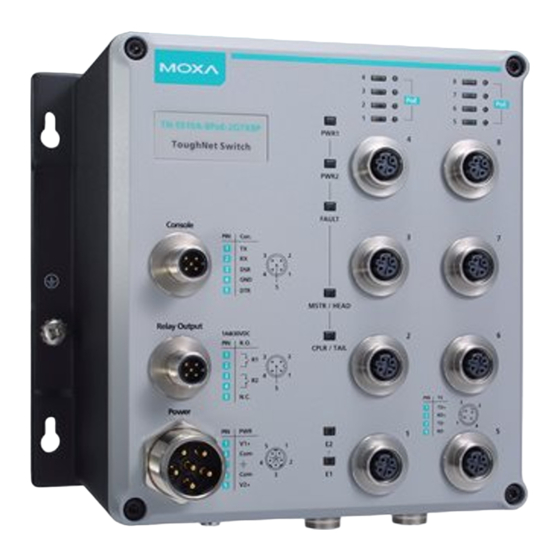
- Page 5 TN-5508A/5510A Panel Layouts - 5 -...
- Page 6 1. Model name. 2. Console port. 3. Relay output port. 4. Power input port (male 5-pin shielded M23 connector). 5. 10/100BaseT(X) port (M12 D-coded 4-pin female connector) 6. PWR1 LED: for power input 1. 7. PWR2 LED: for power input 2. 8.
- Page 7 Mounting Dimensions (unit = mm) TN-5508A Series - 7 -...
- Page 8 TN-5508A-8PoE Series - 8 -...
- Page 9 TN-5510A-2GTX Series - 9 -...
- Page 10 TN-5510A-2GLSX Series - 10 -...
- Page 11 TN-5510A-8PoE-2GTX Series - 11 -...
- Page 12 TN-5510A-8PoE-2GLSX Series - 12 -...
-
Page 13: Panel/Wall Mounting
Panel/Wall Mounting STEP 1: Mounting the TN-5508A/5510A to a wall requires 4 screws. Use the ToughNet switch as a guide to mark the correct positions of the 4 screws. STEP 2: Use the 4 screws in the panel mounting kit. If you would like to use your own screws, make sure the screw head is between 6.0 mm and 7.0 mm in diameter and... -
Page 14: Din-Rail Mounting (Optional)
DIN-Rail Mounting (optional) With the optional DIN-Rail mounting kit DK-DC50131 (must be purchased separately), you can mount the TN-5508A/5510A on a 35mm DIN-Rail. STEP 1: Use 12 screws (6 screws per plate) to attach the two DIN-Rail attachment plates to the rear panel of the switch. -
Page 15: Wiring Requirements
Wiring Requirements WARNING Turn the power off before disconnecting modules or wires. The correct power supply voltage is listed on the product label. Check the voltage of your power source to make sure you are using the correct voltage. Do NOT use a voltage greater than what is specified on the product label. -
Page 16: Grounding The Toughnet Switch
Grounding the ToughNet Switch Grounding and wire routing help limit the effects of noise due to electromagnetic interference (EMI). Run the ground connection from the grounding screw to the grounding surface prior to connecting devices. ATTENTION This product is intended to be mounted to a well-grounded mounting surface such as a metal panel. -
Page 17: Connecting The Relay Outputs
Description Usage Connect “PWR2 Live / DC +” to the PWR2 Live / DC + positive (+) terminal when using a DC power source. STEP 1: Plug your power cord connector to the power input port of the TN- 5508A/5510A switch. STEP 2: Screw the nut on your power cord connector to the power input connector on the switch to ensure a tight connection. - Page 18 Connecting the Data Lines 10/100BaseT(X) Ethernet Port Connection All TN-5508A/5510A models have 8 10/100BaseT(X) Ethernet ports (M12 D-coded 4-pin female connector). The 10/100TX ports located on the TN-5508A/5510A front panel are used to connect to Ethernet- enabled devices. Most users configure these ports for Auto MDI/MDI-X mode, in which case the port’s pinouts are adjusted automatically depending on the type of Ethernet cable used (straight-through or cross-over), and the type of device (NIC-type or HUB/Switch-type)
- Page 19 M12 (4-pin, M) to M12 (4-pin, M) Straight-Trough Cable Wiring M12 (4-pin, M) to RJ45 (8-pin) Cross-Over Cable Wiring M12 (4-pin, M) to RJ45 (8-pin) Straight-Trough Cable Wiring ATTENTION The protective cover must be fixed properly to ensure IP54 protection. Use a torque wrench set to a torque of 4 kgf-m when tightening the screws.
-
Page 20: Led Indicators
Bypass Relay Function The TN-5510A-2GTXBP and TN-5510A-8PoE-2GTXBP models’ two Gigabit Ethernet ports are equipped with a bypass relay function. When the switch is operating normally, these two Gigabit ports work in the same way as the other ports. That is, frame ingressions are processed and then forwarded. - Page 21 Color State Description When the corresponding PORT alarm is enabled, and a user-configured event is triggered. When the corresponding PORT alarm FAULT is enabled and a user-configured event is not triggered, or when the corresponding PORT alarm is disabled. When the TN switch is either the Master of this Turbo Ring, or the Head of this Turbo Chain.
-
Page 22: Support And Assistance
Support and Assistance Visit our website at https://www.moxa.com/en/support where you can find the latest information about the product. - 22 -...
Need help?
Do you have a question about the ToughNet TN-5510A Series and is the answer not in the manual?
Questions and answers