Table of Contents
Advertisement
Quick Links
Quick Installation Guide
Moxa Americas:
Toll-free: 1-888-669-2872
Tel:
1-714-528-6777
Fax:
1-714-528-6778
Moxa Europe:
Tel:
+49-89-3 70 03 99-0
Fax:
+49-89-3 70 03 99-99
Moxa India:
Tel:
+91-80-4172-9088
Fax:
+91-80-4132-1045
TN-5524-8PoE
Moxa ToughNet Switch
Edition 3.0, February 2017
Technical Support Contact Information
www.moxa.com/support
2017 Moxa Inc. All rights reserved.
Moxa China (Shanghai office):
Toll-free: 800-820-5036
Tel:
+86-21-5258-9955
Fax:
+86-21-5258-5505
Moxa Asia-Pacific:
Tel:
+886-2-8919-1230
Fax:
+886-2-8919-1231
P/N: 1802055240012
*1802055240012*
Advertisement
Table of Contents

Related Manuals for Moxa Technologies ToughNet TN-5524-8PoE-P24-T


Summary of Contents for Moxa Technologies ToughNet TN-5524-8PoE-P24-T
- Page 1 TN-5524-8PoE Quick Installation Guide Moxa ToughNet Switch Edition 3.0, February 2017 Technical Support Contact Information www.moxa.com/support Moxa Americas: Moxa China (Shanghai office): Toll-free: 1-888-669-2872 Toll-free: 800-820-5036 Tel: 1-714-528-6777 Tel: +86-21-5258-9955 Fax: 1-714-528-6778 Fax: +86-21-5258-5505 Moxa Europe: Moxa Asia-Pacific: Tel: +49-89-3 70 03 99-0 Tel: +886-2-8919-1230 Fax:...
-
Page 2: Package Checklist
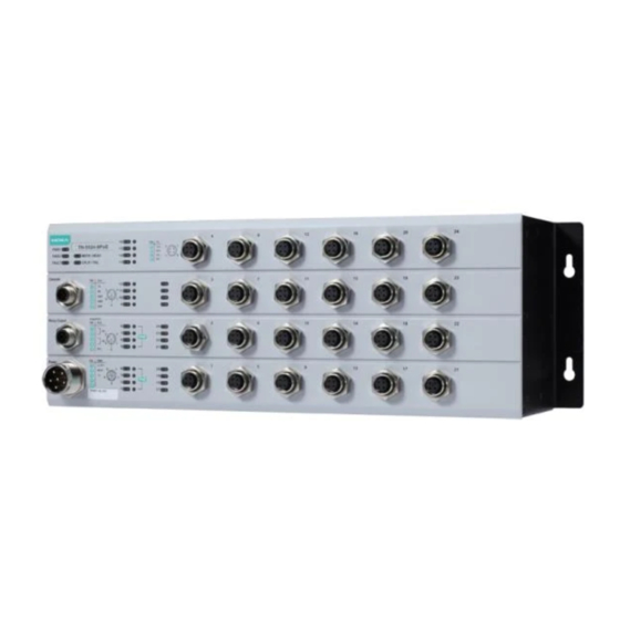
Overview The ToughNet TN-5524-8PoE series M12 managed Ethernet switches are designed for industrial applications in harsh environments. The TN series switches use M12 and other circular connectors to ensure tight, robust connections, and guarantee reliable operation against environmental disturbances, such as vibration and shock. The TN-5524-8PoE series switches provide 24 Fast Ethernet M12 ports, 8 of which are 10/100BaseT(X) PoE compliant. -
Page 3: Recommended Optional Accessories
• 802.3ad, LACP for optimum bandwidth utilization • IEEE802.1X and https/SSL to enhance network security • SNMP v1/v2c/v3 for different levels of network management • RMON for efficient network monitoring and proactive capability • Bandwidth management prevents unpredictable network status •... - Page 4 TN-5524-8PoE Panel Layouts 1. Screw holes for panel mounting kit 2. Console port 3. Grounding screw 4. Relay output port 5. Power input voltage range indication 6. Power input port (male 6-pin shielded M23 connector) 7. PWR1 LED: for power input 1 8.
-
Page 5: Mounting Dimensions
Mounting Dimensions Panel/Wall Mounting STEP 1: Mounting the TN-5524-8PoE switches to a wall requires 4 screws. Use the ToughNet switch as a guide to mark the correct positions of the 4 screws. STEP 2: Use the 4 screws in the panel mounting kit. If you would like to use your own screws, make sure the screw head is between 6.0 mm and 7.0 mm in diameter and the shaft is less than 4.0 mm in... -
Page 6: Wiring Requirements
Wiring Requirements WARNING Turn the power off before disconnecting modules or wires. The correct power supply voltage is listed on the product label. Check the voltage of your power source to make sure you are using the correct voltage. Do NOT use a voltage greater than what is specified on the product label. -
Page 7: Grounding The Toughnet Switch
Grounding the ToughNet Switch Grounding and wire routing help limit the effects of noise due to electromagnetic interference (EMI). Run the ground connection from the grounding screw to the grounding surface prior to connecting devices. ATTENTION This product is intended to be mounted to a well-grounded mounting surface such as a metal panel. -
Page 8: Connecting The Relay Outputs
ATTENTION Before connecting the TN-5524-8PoEto the power input, make sure the power source voltage is stable. Connecting the Relay Outputs Each TN-5524-8PoE switch has two sets of relay outputs—relay output 1 and relay output 2.The M12 A-coded 5-pin male connector on the TN-5524-8PoE’s front panel is used for the two relay outputs. - Page 9 Pinouts for the RJ45 (8-pin) Port 8-pin RJ45 MDI Port Pinouts MDI-X Port Pinouts Signal Signal M12 (4-pin, M) to M12 (4-pin, M) Cross-Over Cable Wiring M12 (4-pin, M) to M12 (4-pin, M) Straight-Trough Cable Wiring M12 (4-pin, M) to RJ45 (8-pin) Cross-Over Cable Wiring M12 (4-pin, M) to RJ45 (8-pin) Straight-Trough Cable Wiring - 9 -...
-
Page 10: Led Indicators
LED Indicators Several LED indicators are located on the ToughNet switch’s front panel. The function of each LED is described in the table below. Color State Description System LEDs Power is being supplied to power input PWR1. PWR1 AMBER Power is not being supplied to power input PWR1 Power is being supplied to power input PWR2. -
Page 11: Specifications
Specifications Technology Standards IEEE 802.3 for 10BaseT IEEE 802.3u for 100BaseT(X) IEEE 802.af PoE IEEE 802.3x for Flow Control IEEE 802.1D for Spanning Tree Protocol IEEE 802.1w for Rapid STP IEEE 802.1Q for VLAN Tagging IEEE 802.1p for Class of Service IEEE 802.1X for Authentication IEEE 802.3ad for Port Trunk with LACP Protocols... - Page 12 Environmental Limits Operating Temperature Wide Temp. Models: -40 to 75°C (-40 to 167°F) Storage Temperature -40 to 85°C (-40 to 185°F) Operating Humidity 5 to 95% (non-condensing) Regulatory Approvals Safety UL/cUL 508 FCC Part 15 Subpart B Class A, EN 55032 Class A IEC 61000-4-2 ESD: Contact: 6 kV;...
Need help?
Do you have a question about the ToughNet TN-5524-8PoE-P24-T and is the answer not in the manual?
Questions and answers