Table of Contents

Related Manuals for Moxa Technologies ToughNet Switch TN-5500 series


Summary of Contents for Moxa Technologies ToughNet Switch TN-5500 series
- Page 1 Moxa ToughNet Switch TN-5500/5518 Series Layer 2 M12 managed 16/16+2G-port Ethernet Switches User’s Manual www.moxa.com/product First Edition, October 2009 © 2009 Moxa Inc. All rights reserved. Reproduction without permission is prohibited.
-
Page 2: Copyright Notice
Moxa ToughNet Switch TN-5500/5518 Series User’s Manual The software described in this manual is furnished under a license agreement and may be used only in accordance with the terms of that agreement. Copyright Notice Copyright © 2009 Moxa Inc. All rights reserved. Reproduction without permission is prohibited. -
Page 3: Table Of Contents
Table of Contents Chapter 1 Introduction ....................1-1 Overview ........................1-2 Package Checklist ....................1-2 Software Features ....................1-2 Recommended Optional Accessories..............1-3 Chapter 2 Getting Started ..................2-1 RS-232 Console Configuration (115200, None, 8, 1, VT100) ......... 2-2 Configuration by Telnet Console................2-5 Configuration by Web Browser ................ - Page 4 Using Multicast Filtering..................3-61 The Concept of Multicast Filtering............... 3-61 Configuring IGMP Snooping................ 3-64 Add Static Multicast MAC ................3-66 Configuring GMRP ..................3-67 GMRP Table....................3-67 Using Bandwidth Management................3-68 Configuring Bandwidth Management ............3-68 Broadcast Storm Protection ................ 3-68 Traffic Rate Limiting Settings ..............
-
Page 5: Chapter 1 Introduction
Introduction Chapter 1 Welcome to the Moxa ToughNet Switch TN-5500 Series, a managed redundant Ethernet switch designed especially for connecting Ethernet-enabled devices for industrial field applications. The following topics are covered in this chapter: Overview Package Checklist Software Features Recommended Optional Accessories... -
Page 6: Overview
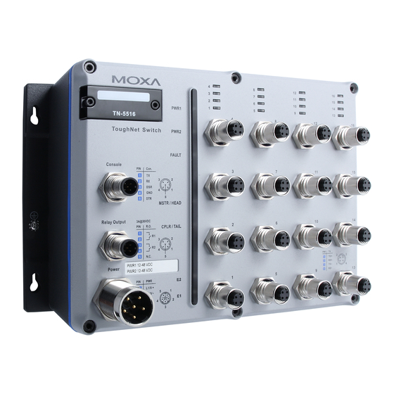
TN-5516/5518 Series User’s Manual Introduction Overview The ToughNet TN-5516/5518 series M12 managed Ethernet switches are designed for industrial applications in harsh environments. The TN series switches use M12 and other circular connectors to ensure tight, robust connections, and guarantee reliable operation against environmental disturbances, such as vibration and shock. -
Page 7: Recommended Optional Accessories
TN-5516/5518 Series User’s Manual Introduction Automatic recovery of connected device’s IP addresses Line-swap fast recovery LLDP for automatic topology discovery in network management software Configurable by Web browser, Telnet/serial console, and Windows utility Recommended Optional Accessories CBL-M23(FF5P)Open-BK-100-IP67: 1-meter M23-to-5-pin power cable with IP67-rated female 5-pin M23 connector. -
Page 8: Chapter 2 Getting Started
Getting Started Chapter 2 This chapter explains the initial installation process for the TN-5500. There are three ways to access the TN-5500’s configuration settings: the serial console, Telnet console, and web console. If you do not know the TN-5500’s IP address, you can open the serial console by connecting the TN-5500 to a PC’s COM port with a short serial cable. -
Page 9: Console Configuration (115200, None, 8, 1, Vt100)
TN-5516/5518 User’s Manual Getting Started RS-232 Console Configuration (115200, None, 8, 1, VT100) NOTE You cannot connect to the serial and Telnet console at the same time. You can connect to the web console and another console (serial or Telnet) at the same time. However, it is strongly recommended that you do NOT do so. - Page 10 TN-5516/5518 User’s Manual Getting Started The Property window should open. On the Communication Parameter tab for Ports, select the COM port that is being used for the console connection. Set the other fields as follows: 115200 for Baud Rate, 8 for Data Bits, None for Parity, and 1 for Stop Bits. 4.
- Page 11 TN-5516/5518 User’s Manual Getting Started The serial console will prompt you to log in. Press Enter and select admin or user. Use the down arrow key on your keyboard to select the Password field and enter a password if desired. This password will be required to access any of the consoles (web, serial, Telnet). If you do not wish to create a password, leave the Password field blank and press Enter.
-
Page 12: Configuration By Telnet Console
TN-5516/5518 User’s Manual Getting Started Configuration by Telnet Console You may open the TN-5500’s Telnet or web console over a network. This requires that the PC host and TN-5500 are on the same logical subnet. You may need to adjust your PC host’s IP address and subnet mask. - Page 13 TN-5516/5518 User’s Manual Getting Started The Telnet console will prompt you to log in. Press Enter and select admin or user. Use the down arrow key on your keyboard to select the Password field and enter a password if desired. This password will be required to access any of the consoles (web, serial, Telnet). If you do not wish to create a password, leave the Password field blank and press Enter.
-
Page 14: Configuration By Web Browser
TN-5516/5518 User’s Manual Getting Started Use the following keys on your keyboard to navigate the TN-5500’s Telnet console: Function Up, down, right, left arrow keys Move the onscreen cursor Enter Display and select options Space Toggle options Previous menu NOTE The Telnet console looks and operates in precisely the same manner as the serial console. - Page 15 TN-5516/5518 User’s Manual Getting Started After making sure that the TN-5500 is connected to the same LAN and logical subnet as your PC, open the TN-5500’s web console as follows: 1. Point your web browser to the TN-5500’s IP address by entering it in the Address or URL field.
-
Page 16: Disabling Telnet And Browser Access
TN-5516/5518 User’s Manual Getting Started 3. After logging in, you may need to wait a few moments for the web console to appear. Use the folders in the left navigation panel to navigate between different pages of configuration options. Disabling Telnet and Browser Access If you are connecting the TN-5500 to a public network but do not intend to manage it over the network, we suggest disabling both the Telnet and web consoles. -
Page 17: Chapter 3 Featured Functions
Featured Functions Chapter 3 This chapter explains how to access TN-5500’s various configuration, monitoring, and administration functions. These functions can be accessed by serial, Telnet, or web console. The serial console can be used if you do not know TN-5500’s IP address and requires that you connect the TN-5500 to a PC COM port. -
Page 18: Configuring Basic Settings
TN-5516/5518 User’s Manual Featured Functions Configuring Basic Settings Basic Settings includes the most common settings required by administrators to maintain and control the TN-5500. System Identification System Identification items are displayed at the top of the web console and will be included in alarm emails. -
Page 19: Password
TN-5516/5518 User’s Manual Featured Functions Maintainer Contact Info Setting Description Factory Default Max. 30 This option is useful for providing information None characters about who is responsible for maintaining this unit and how to contact this person. Web Configuration Setting Description Factory Default http or https/... -
Page 20: Accessible Ip
TN-5516/5518 User’s Manual Featured Functions Account Setting Description Factory Default Admin This account can modify the TN-5500’s configuration. admin User This account can only view the TN-5500’s configurations. Password Setting Description Factory Default Old password Enter the current password None (max. -
Page 21: Port Settings
TN-5516/5518 User’s Manual Featured Functions Grant acces to all hosts Make sure the accessible IP list is not enabled. Remove the checkmark from Enable the accessible IP list. The following table shows additional configuration examples: Hosts That Need Access Input Format Any host Disable 192.168.1.120... - Page 22 TN-5516/5518 User’s Manual Featured Functions ATTENTION If a connected device or sub-network is wreaking havoc on the rest of the network, the Disable option under Advanced Settings/Port gives the administrator a quick way to shut off access through this port immediately. Description Setting Description...
-
Page 23: Network Settings
TN-5516/5518 User’s Manual Featured Functions MDI/MDIX Setting Description Factory Default Auto This allows the port to auto-detect the port type of the connected Ethernet device and change the port type accordingly. Auto Choose MDI or MDIX if the connected Ethernet device has trouble auto-negotiating for port type. - Page 24 TN-5516/5518 User’s Manual Featured Functions NOTE 1. The TN-5500 Series is equipped with a “Hardware-based IP configuration” feature through the 3 rotary switches physically mounted on the product's front panel. Please reference the Hardware Installation Guide for how to configure. 2.
- Page 25 TN-5516/5518 User’s Manual Featured Functions IPv6 IPv6 settings include two distinct address types: Link-Local Unicast address and Global Unicast address. A Link-Local address makes the switch accessible over IPv6 for all devices attached to the same local subnet. To connect to a larger network with multiple segments, the switch must be configured with a Global Unicast address.
-
Page 26: Neighbor Cache
TN-5516/5518 User’s Manual Featured Functions Link-Local Address Setting Description Factory Default None The network portion of Link-Local address is FE80: (EUI-64 FE80 and the host portion of Link-Local form of the MAC address is automatically generated using the address) modified EUI-64 form of the interface identifier (Switch’s MAC address). -
Page 27: System Time Settings
TN-5516/5518 User’s Manual Featured Functions System Time Settings The TN-5500 has a time calibration function based on information from an NTP server or user specified time and date. Functions such as automatic warning emails can therefore include time and date stamp. NOTE The TN-5500 does not have a real time clock. -
Page 28: Daylight Saving Time
TN-5516/5518 User’s Manual Featured Functions Daylight Saving Time The Daylight Saving Time settings are used to automatically offset the TN-5500’s time forward according to national standards. Start Date Setting Description Factory Default User-specified date This specifies the date that Daylight Savings None Time begins. -
Page 29: Configuring Ieee 1588/Ptp
TN-5516/5518 User’s Manual Featured Functions Time Server Query Period Setting Description Factory Default Query period This parameter determines how frequently the 600 seconds time is updated from the NTP server. Enable NTP/SNTP Server Setting Description Factory Default Enable/Disable This enables or disables NTP or SNTP server. Disable Configuring IEEE 1588/PTP Time may be accomplished using the IEEE Standard for a Precision Clock Synchronization... - Page 30 TN-5516/5518 User’s Manual Featured Functions Basic Ethernet Communication with IEEE 1588 PTP Topology. 3-14...
-
Page 31: Ptp Setting
TN-5516/5518 User’s Manual Featured Functions PTP Setting Operation IEEE 1588/PTP Setting Description Factory Default Operation Disable or enable IEEE 1588(PTP) operation Disable Configuration IEEE 1588/PTP Setting Description Factory Default Clock Mode Support software-based IEEE 1588(PTP) mode Disable Sync Interval Period for sending synchronization message (in Disable seconds) Subdomain Name... -
Page 32: System File Update-By Remote Tftp
TN-5516/5518 User’s Manual Featured Functions System File Update—By Remote TFTP The TN-5500 supports saving your configuration or log file to a remote TFTP server or local host. Other TN-5500 switches can also load the configuration at a later time. The TN-5500 also supports loading firmware or configuration files from the TFTP server or a local host. -
Page 33: System File Update-By Local Import/Export
TN-5516/5518 User’s Manual Featured Functions System File Update—By Local Import/Export Configuration File Click Export to save the TN-5500’s configuration file to the local host. Log File Click Export to save the TN-5500’s log file to the local host. NOTE Some operating systems will open the configuration file and log file directly in the web page. In such cases, right click the Export button to save the file. -
Page 34: Restart
TN-5516/5518 User’s Manual Featured Functions Auto load system configurations when system boots up Setting Description Factory Default Enables Auto load system configurations when Enable system boots up Enable Disables Auto load system configurations when Disable system boots up Save the current configurations to ABC To export the current configuration file of the TN-5500, click on Save to save it to the ABC. -
Page 35: Using Port Trunking
TN-5516/5518 User’s Manual Featured Functions Using Port Trunking Link aggregation involves grouping links to into a link aggregation group. A MAC client can treat link aggregation groups as if they were a single link. The TN-5500’s port trunking feature allows devices to communicate by aggregating up to 3 trunk groups, with a maximum of 8 ports for each group. -
Page 36: Configuring Port Trunking
TN-5516/5518 User’s Manual Featured Functions Configuring Port Trunking The Port Trunking Settings page is where ports are assigned to a trunk group. Step 1: Select the desired Trunk Group (Trk1, Trk2, Trk3). Step 2: Select the Trunk Type (Static or LACP). Step 3: Select the desired ports under Available Ports and click Up to add to the Trunk Group. - Page 37 TN-5516/5518 User’s Manual Featured Functions Available Ports/Member Ports Setting Description Factory Default Member/available ports This lists the ports in the current trunk group and the ports that are available to be added. Check box This selects the port to be added or removed from Unchecked the group.
-
Page 38: Configuring Snmp
TN-5516/5518 User’s Manual Featured Functions Configuring SNMP The TN-5500 supports SNMP V1, V2c, and V3. SNMP V1 and SNMP V2c use a community string match for authentication, which means that SNMP servers access all objects with read-only or read/write permissions using the community strings public and private by default. SNMP V3 requires that you select an authentication level of MD5 or SHA, and is the most secure protocol. -
Page 39: Snmp Read/Write Settings
TN-5516/5518 User’s Manual Featured Functions These parameters are configured on the SNMP page. A more detailed explanation of each parameter is given below the figure. SNMP Read/Write Settings SNMP Versions Setting Description Factory Default V1, V2c, V3, or This specifies the SNMP protocol version V1, V2c, or V3 V1, V2c used to manage the switch. - Page 40 TN-5516/5518 User’s Manual Featured Functions V1, V2c Write/Read Community Setting Description Factory Default This specifies the community string to authenticate the SNMP agent for read/write Max. 30 characters access. The SNMP server will access all Private objects with read/write permissions using this community string.
-
Page 41: Trap Settings
TN-5516/5518 User’s Manual Featured Functions User Data Encryption Key (for SNMP V1, V2c, V3 and V3 only) Setting Description Factory Default This enables data encryption using the Enable specified data encryption key (between 8 and 30 characters). Disable No data encryption Trap Settings Trap Server IP/Name Setting... -
Page 42: Private Mib Information
TN-5516/5518 User’s Manual Featured Functions Retries (1-99) Setting Description Factory Default The maximum number of retries is 99 times Disable when Trap (default is 1 time). When the SNMP agent Mode is “Trap”, 1 1 to 99 receives acknowledgement from the NMS, it when Trap Mode is will stop resending the inform messages. -
Page 43: The Turbo Ring Concept
TN-5516/5518 User’s Manual Featured Functions NOTE Most managed switches by Moxa support two proprietary Turbo Ring protocols: Turbo Ring refers to the original version of Moxa’s proprietary redundant ring protocol, which has a recovery time of under 300 ms. Turbo Ring V2 refers to the new generation Turbo Ring, which has a recovery time of under 20 ms. - Page 44 TN-5516/5518 User’s Manual Featured Functions Determining the Redundant Path for Turbo Ring In this case, the redundant segment (i.e., the segment that will be blocked during normal operation) is determined by the number of TN series Ethernet switches in the ring and by the location of the master switch.
- Page 45 TN-5516/5518 User’s Manual Featured Functions Determining the Redundant Path for Turbo Ring V2 Master For Turbo Ring V2, the backup segment is the segment connected to the 2nd redundant port on the master. Please refer to Configuring Turbo Ring V2 later in this chapter.
- Page 46 TN-5516/5518 User’s Manual Featured Functions Select two ports on each switch to be used as coupling ports and link them together. Next, assign one switch (e.g., Switch A) to be the coupler and connect the coupler’s coupling control port with Switch B (for this example).
- Page 47 TN-5516/5518 User’s Manual Featured Functions Dual-Ring Configuration (applies only to “Turbo Ring V2”) The “dual-ring” option, in which two adjacent rings share one switch, provides another ring coupling configuration. This type of configuration is ideal for applications that have inherent cabling difficulties.
-
Page 48: Configuring Turbo Ring, Turbo Ring V2
TN-5516/5518 User’s Manual Featured Functions Configuring Turbo Ring, Turbo Ring V2 On the Communication Redundancy page, select Turbo Ring or Turbo Ring V2 as the Redundancy Protocol. Note that each protocol’s configuration page is different. Configuring Turbo Ring "Current Status" Items Now Active This shows which communication protocol is in use: Turbo Ring, Turbo Ring V2, RSTP, Turbo Chain, or none. - Page 49 TN-5516/5518 User’s Manual Featured Functions "Settings" Items Redundancy Protocol Setting Description Factory Default Turbo Ring This selects the Turbo Ring protocol. Turbo Ring V2 This selects the Turbo Ring V2 protocol. RSTP None This selects the RSTP protocol. (IEEE802.1w/1D) Turbo Chain This selects the Turbo Chain protocol.
- Page 50 TN-5516/5518 User’s Manual Featured Functions Coupling Control Port Setting Description Factory Default This specifies which port on the TN-5500 Coupling Control Port None will be used as the coupling control port. Configuring Turbo Ring V2 NOTE When using a dual-ring architecture, users must complete configuration for both Ring 1 and Ring 2.
- Page 51 TN-5516/5518 User’s Manual Featured Functions NOTE The user does not need to assign the master to use Turbo Ring or Turbo Ring V2. If no master is assigned, the Turbo Ring protocol will automatically assign master status to one of the TN series Ethernet switches in the ring.
- Page 52 TN-5516/5518 User’s Manual Featured Functions Redundant Ports Setting Description Factory Default This specifies which port on the TN-5500 1st Port None will be used as the first redundant port. This specifies which port on the TN-5500 2nd Port None will be used as the second redundant port. Enable Ring Coupling Setting Description...
-
Page 53: The Turbo Chain Concept
TN-5516/5518 User’s Manual Featured Functions The Turbo Chain Concept Moxa developed the proprietary Turbo Chain protocol to optimize communication redundancy and achieve a fast network recovery time. Turbo Chain is an advanced software-technology that gives network administrators the flexibility of being able to construct any type of redundant network topology. - Page 54 TN-5516/5518 User’s Manual Featured Functions Turbo Turbo Turbo Chain 3 Chain 1 Chain 2 Turbo Chain 4 RSTP Turbo Chain 3-38...
-
Page 55: Configuring Turbo Chain
TN-5516/5518 User’s Manual Featured Functions Initial Setup for Turbo Chain Select the Head switch, Tail switch, and Member switches in the chain. Configure one port as the Head port and one port as the Member port in the Head switch, one port as the Tail port and one port as the Member port in the Tail switch, and two ports as Member ports in the Member switches. - Page 56 TN-5516/5518 User’s Manual Featured Functions Member Switch Configuration Tail Switch Configuration “Current Status” Items Now Active Shows which communication protocol is in use: Turbo Ring, Turbo Ring V2, RSTP, Turbo Chain or None. 3-40...
- Page 57 TN-5516/5518 User’s Manual Featured Functions “Settings” Items Redundancy Protocol Setting Description Factory Default Turbo Ring This selects the Turbo Ring protocol. Turbo Ring V2 This selects the Turbo Ring V2 protocol. Turbo Chain This selects the Turbo Chain protocol. None RSTP (IEEE This selects the RSTP protocol.
-
Page 58: The Stp/Rstp Concept
TN-5516/5518 User’s Manual Featured Functions The STP/RSTP Concept Spanning Tree Protocol (STP) was designed to help reduce link failures in a network and provide protection from loops. Networks that have a complicated architecture are prone to broadcast storms caused by unintended loops in the network. The TN-5500’s STP feature is disabled by default. - Page 59 TN-5516/5518 User’s Manual Featured Functions If STP is enabled, it will detect duplicate paths and prevent, or block, one of them from forwarding traffic. In the following example, STP determined that traffic from LAN segment 2 to LAN segment 1 should flow through Bridges C and A because this path has a greater bandwidth and is therefore more efficient.
-
Page 60: How Stp Works
TN-5516/5518 User’s Manual Featured Functions How STP Works When enabled, STP determines the most appropriate path for traffic through a network. The method is described below: STP Requirements Before STP can configure the network, the system must satisfy the following requirements: Communication must be established between all bridges. -
Page 61: Stp Reconfiguration
TN-5516/5518 User’s Manual Featured Functions STP Reconfiguration Once the network topology has stabilized, each bridge listens for “Hello” BPDUs that are transmitted from the Root Bridge at regular intervals. If a bridge does not receive a “Hello” BPDU after a certain interval (the Max Age time), the bridge assumes that the Root Bridge, or a link between itself and the Root Bridge, has gone down. -
Page 62: Using Stp On A Network With Multiple Vlans
TN-5516/5518 User’s Manual Featured Functions Bridge A has been selected as the Root Bridge, since it was determined to have the lowest Bridge Identifier on the network. Since Bridge A is the Root Bridge, it is also the Designated Bridge for LAN segment 1. Port 1 on Bridge A is selected as the Designated Bridge Port for LAN Segment 1. -
Page 63: Configuring Stp/Rstp
TN-5516/5518 User’s Manual Featured Functions Configuring STP/RSTP The following figures indicate which Spanning Tree Protocol parameters can be configured. A more detailed explanation of each parameter is given below the figure. At the top of this page, the user can check the Current Status of this function. For RSTP, you will see: Now Active: This field shows which communication protocol is being used—Turbo Ring, Turbo Ring V2,... - Page 64 TN-5516/5518 User’s Manual Featured Functions Forwarding Delay Setting Description Factory Default Numerical value input by This specifies the amount of time this device 15 (sec.) user will wait before checking to see if it should change to a different state. Hello Time (sec.) Setting Description...
-
Page 65: Using Traffic Prioritization
TN-5516/5518 User’s Manual Featured Functions Configuration Limits of RSTP/STP The Spanning Tree Algorithm places limits on three of the configuration items: ≦ ≦ [Eq. 1]: 1 sec Hello Time 10 sec ≦ ≦ [Eq. 2]: 6 sec Max. Age 40 sec ≦... -
Page 66: How Traffic Prioritization Works
TN-5516/5518 User’s Manual Featured Functions How Traffic Prioritization Works Traffic prioritization uses the four traffic queues that are present in your TN-5500 to ensure that high priority traffic is forwarded on a different queue from lower priority traffic. This is what provides Quality of Service (QoS) to your network. -
Page 67: Traffic Prioritization
TN-5516/5518 User’s Manual Featured Functions Advantages of DiffServ over IEEE 802.1D are: Configure how you want your switch to treat selected applications and types of traffic by assigning various grades of network service to them. No extra tags are required in the packet. DSCP uses the IP header of a packet and therefore priority is preserved across the Internet. -
Page 68: Configuring Traffic Prioritization
TN-5516/5518 User’s Manual Featured Functions Configuring Traffic Prioritization Quality of Service (QoS) provides a traffic prioritization capability to ensure that important data is delivered consistently and predictably. The TN-5500 can inspect IEEE 802.1p/1Q layer 2 CoS tags, and even layer 3 TOS information, to provide a consistent classification of the entire network. The TN-5500’... -
Page 69: Cos Mapping
TN-5516/5518 User’s Manual Featured Functions Port Highest Priority Setting Description Factory Default Enable/Disable Queue the port priority of ingress frames to “High” Disable Inspect TOS Setting Description Factory Default Enable/Disable This enables or disables the TN-5500 to inspect the Enable Type of Service (TOS) bits in IPV4 frame to determine the priority of each frame. - Page 70 TN-5516/5518 User’s Manual Featured Functions Setting Description Factory 0: Low 1: Low 2: Normal Low/Normal/ This maps different CoS values to 4 different egress 3: Normal Medium/High queues. 4: Medium 5: Medium 6: High 7: High TOS/DiffServ Mapping Setting Description Factory Default 1 to 16: Low Low/Normal/...
-
Page 71: Using Virtual Lan
TN-5516/5518 User’s Manual Featured Functions Using Virtual LAN Setting up Virtual LANs (VLANs) on your TN-5500 increases the efficiency of your network by dividing the LAN into logical segments, as opposed to physical segments. In general, VLANs are easier to manage. The Virtual LAN (VLAN) Concept What is a VLAN? A VLAN is a group of devices that can be located anywhere on a network, but which... -
Page 72: Managing A Vlan
TN-5516/5518 User’s Manual Featured Functions VLANs and the ToughNet switch Your TN-5500 provides support for VLANs using IEEE Std 802.1Q-1998. This standard allows traffic from multiple VLANs to be carried across one physical link. The IEEE Std 802.1Q-1998 standard allows each port on your TN-5500 to be placed as follows: In a single VLAN defined on the TN-5500. -
Page 73: Sample Applications Of Vlans Using Tn-5500
TN-5516/5518 User’s Manual Featured Functions The TN-5500 supports two types of VLAN port settings: Access Port: The port connects to a single device that is not tagged. The user must define the default port PVID that assigns which VLAN the device belongs to. Once the ingress packet of this Access Port egresses to another Trunk Port (the port needs all packets to carry tag information), TN-5500 will insert this PVID into this packet to help the next 802.1Q VLAN switch recognize it. -
Page 74: Configuring Virtual Lan
TN-5516/5518 User’s Manual Featured Functions After proper configuration: Packets from Device A will travel through Trunk Port 3 with tagged VID 5. Switch B will recognize its VLAN, pass it to port 6, and then remove tags received successfully by Device G, and vice versa. - Page 75 TN-5516/5518 User’s Manual Featured Functions Management VLAN ID Setting Description Factory Default VLAN ID from 1 This assigns the VLAN ID of this TN-5500. to 4094 Enable GVRP Setting Description Factory Default Enable or Disable Enable or disable GVRP (GARP VLAN Registration Enable Protocol).
-
Page 76: Vlan Table
TN-5516/5518 User’s Manual Featured Functions To configure the TN-5500’s port-based VLAN, use the VLAN settings page to configure the ports. VLAN Mode Setting Description Factory Default 802.1Q VLAN Set VLAN mode to 802.1Q VLAN 802.1Q VLAN Port-based VLAN Set VLAN mode to Port-based VLAN Port Setting Description... -
Page 77: Using Multicast Filtering
TN-5516/5518 User’s Manual Featured Functions NOTE The physical network can have a maximum of 64 VLAN settings. Using Multicast Filtering Multicast filtering improves the performance of networks that carry multicast traffic. This section explains multicasts, multicast filtering, and how multicast filtering can be implemented on your TN-5500. -
Page 78: Multicast Filtering
TN-5516/5518 User’s Manual Featured Functions Multicast Filtering Multicast filtering ensures that only end-stations that have joined certain groups receive multicast traffic. With multicast filtering, network devices only forward multicast traffic to the ports that are connected to registered end-stations. The following two figures illustrate how a network behaves without multicast filtering, and with multicast filtering. -
Page 79: Igmp Multicast Filtering
TN-5516/5518 User’s Manual Featured Functions Multicast Filtering and Moxa’s ToughNet switches The TN-5500 has three ways to achieve multicast filtering: IGMP (Internet Group Management Protocol) Snooping, GMRP (GARP Multicast Registration Protocol), and adding a static multicast MAC manually to filter multicast traffic automatically. IGMP (Internet Group Management Protocol) Snooping Mode Snooping Mode allows your switch to forward multicast packets only to the appropriate ports. -
Page 80: Configuring Igmp Snooping
TN-5516/5518 User’s Manual Featured Functions GMRP (GARP Multicast Registration Protocol) The TN-5500 supports IEEE 802.1D-1998 GMRP (GARP Multicast Registration Protocol), which differs from IGMP (Internet Group Management Protocol). GMRP is a MAC-based multicast management protocol, whereas IGMP is IP-based. GMRP provides a mechanism that allows bridges and end stations to register or de-register Group membership information dynamically. - Page 81 TN-5516/5518 User’s Manual Featured Functions IGMP Snooping Enhanced Mode Setting Description Factory Default Enable IGMP Multicast packets will be forwarded to: Enable - Auto-Learned Multicast Querier Ports - Member Ports Disable IGMP Multicast packets will be forwarded to: - Auto-Learned Multicast Querier Ports - Static Multicast Querier Ports - Querier Connected Ports - Member Ports...
-
Page 82: Add Static Multicast Mac
TN-5516/5518 User’s Manual Featured Functions Add Static Multicast MAC If required, the TN-5500 also supports adding multicast groups manually. Add New Static Multicast Address to the List Setting Description Factory Default MAC Address Input the multicast MAC address of this host. None MAC Address Setting... -
Page 83: Configuring Gmrp
TN-5516/5518 User’s Manual Featured Functions Configuring GMRP GMRP is a MAC-based multicast management protocol, whereas IGMP is IP-based. GMRP provides a mechanism that allows bridges and end stations to register or un-register Group membership information dynamically. GMRP enable Setting Description Factory Default Enable/Disable This enables or disables the GMRP function for the port... -
Page 84: Using Bandwidth Management
TN-5516/5518 User’s Manual Featured Functions Using Bandwidth Management In general, one host should not be allowed to occupy unlimited bandwidth, particularly when the device malfunctions. For example, so-called “broadcast storms” could be caused by an incorrectly configured topology, or a malfunctioning device. The TN-5500 not only prevents broadcast storms, but can also be configured to a different ingress rate for all packets, giving administrators full control of their limited bandwidth to prevent undesirable effects caused by unpredictable faults. -
Page 85: Traffic Rate Limiting Settings
TN-5516/5518 User’s Manual Featured Functions Traffic Rate Limiting Settings Ingress Setting Description Factory Default Ingress rate Select the ingress rate for all packets from the following options: Not Limited, 3%, 5%, 10%, 15%, 25%, 35%, 50%, 65%, 85% 3-69... -
Page 86: Using Port Access Control
TN-5516/5518 User’s Manual Featured Functions Using Port Access Control The TN-5500 provides two kinds of Port-Base Access Control. One is Static Port Lock and the other is IEEE 802.1X. Static Port Lock The TN-5500 can also be configured to protect static MAC addresses for a specific port. With the Port Lock function, these locked ports will not learn any additional addresses, but only allow traffic from preset static MAC addresses, helping to block hackers and careless usage. - Page 87 TN-5516/5518 User’s Manual Featured Functions Message Exchange Authentication server Client (RADIUS) EAPOL-Start EAP-Request/Identity EAP-Response/Identity RADIUS Access-Request RADIUS Access-Challenge EAP-Request/OTP RADIUS Access-Request EAP-Response/OTP EAP-Success RADIUS Access-Accept Port Authorized EAPOL-Logoff Port Unauthorized 1. When the supplicant receives an “EAP Request/Identity” frame, it sends an “EAP Response/Identity”...
-
Page 88: Configuring Static Port Lock
TN-5516/5518 User’s Manual Featured Functions Configuring Static Port Lock The TN-5500 supports adding unicast groups manually if required. Setting Description Factory Default MAC Address Add the static unicast MAC address into the address None table. Port Fix the static address with a dedicated port. Configuring IEEE 802.1X 3-72... - Page 89 TN-5516/5518 User’s Manual Featured Functions Database Option Setting Description Factory Default Local Select this option when setting the Local User Database Local (Max. 32 users) as the authentication database. Radius Select this option to set an external RADIUS server as Local the authentication database.
- Page 90 TN-5516/5518 User’s Manual Featured Functions 802.1X Re-Authentication The TN-5500 can force connected devices to be re-authorized manually. 802.1X Re-Authentication Setting Description Factory Default Enable/Disable This enables or disables 802.1X Re-Authentication Disable Local User Database Setup When setting the Local User Database as the authentication database, set the database first. Local User Database Setup Setting Description...
-
Page 91: Using Auto Warning
TN-5516/5518 User’s Manual Featured Functions Port Access Control Table The port status will show authorized or unauthorized. Using Auto Warning Since industrial Ethernet devices are often located at the endpoints of a system, these devices will not always know what is happening elsewhere on the network. This means that an industrial Ethernet switch that connects to these devices must provide system maintainers with real-time alarm messages. -
Page 92: Event Type
TN-5516/5518 User’s Manual Featured Functions Event Type Event Types can be divided into two basic groups: System Events and Port Events. System Events are related to the overall function of the switch, whereas Port Events are related to the activity of a specific port. System Events Warning e-mail is sent when…... -
Page 93: Email Setup
TN-5516/5518 User’s Manual Featured Functions Port Events Warning e-mail is sent when… Link-ON The port is connected to another device. The port is disconnected (e.g., the cable is pulled out, Link-OFF or the opposing device shuts down). The port’s traffic surpasses the Traffic-Threshold for Traffic-Overload that port (provided this item is Enabled). -
Page 94: Configuring Relay Warning
TN-5516/5518 User’s Manual Featured Functions Mail Server IP/Name Setting Description Factory Default IP address The IP Address of your email server. None Account Name Setting Description Factory Default Max. 45 Charters Your email account. None Password Setting Setting Description Factory Default Disable/Enable to To reset the password from the Web Browser interface, Disable... -
Page 95: Event Setup
TN-5516/5518 User’s Manual Featured Functions Event Setup Event Types can be divided into two basic groups: System Events and Port Events. System Events are related to the overall function of the switch, whereas Port Events are related to the activity of a specific port. The TN-5500 supports two relay outputs. -
Page 96: Warning List
TN-5516/5518 User’s Manual Featured Functions NOTE The Traffic-Overload, Traffic-Threshold (%), and Traffic-Duration (sec) Port Event items are related. If you Enable the Traffic-Overload event, then be sure to enter a nonzero Traffic-Threshold percentage, as well as a Traffic-Duration between 1 and 300 seconds. Override relay warning settings Click the checkbox to override the relay warning setting temporarily. -
Page 97: Using Set Device Ip
TN-5516/5518 User’s Manual Featured Functions Using Set Device IP To reduce the effort required to set up IP addresses, the TN-5500 comes equipped with DHCP/BootP server and RARP protocol to set up IP addresses of Ethernet-enabled devices automatically. When enabled, the Set device IP function allows TN-5500 to assign specific IP addresses automatically to connected devices that are equipped with DHCP Client or RARP protocol. -
Page 98: Configuring Set Device Ip
TN-5516/5518 User’s Manual Featured Functions Configuring Set Device IP Desired IP Address Setting Description Factory Default IP Address Set the desired IP of connected devices. None Configuring DHCP Relay Agent The DHCP Relay Agent makes it possible for DHCP broadcast messages to be sent over routers. The DHCP Relay Agent enables DHCP clients to obtain IP addresses from a DHCP server on a remote subnet, or those that are not located on the local subnet. - Page 99 TN-5516/5518 User’s Manual Featured Functions Where the first byte “FF” is fixed to “01”, the second and the third byte “VV-VV” is formed by the port VLAN ID in hex, and the last byte “PP” is formed by the port number in hex. For example, 01–00–0F–03 is the “Circuit ID”...
-
Page 100: Dhcp Option 82
TN-5516/5518 User’s Manual Featured Functions Server Setting Description Factory Default IP address for the This assigns the IP address of the 3rd DHCP server that None 3rd DHCP server the switch tries to access. Server Setting Description Factory Default IP address for the This assigns the IP address of the 4th DHCP server that None 4th DHCP server... -
Page 101: Using Diagnosis
TN-5516/5518 User’s Manual Featured Functions Using Diagnosis The TN-5500 provides two important tools for administrators to diagnose network systems. Mirror Port The Mirror port function can be used to monitor data being transmitted through the specific ports. This is done by setting up another port (the mirror port) to receive the same data being transmitted from, or both to and from, the ports under observation. -
Page 102: Ping
TN-5516/5518 User’s Manual Featured Functions Ping The Ping function uses the ping command to give users a simple but powerful tool for troubleshooting network problems. The function’s most unique feature is that even though the ping command is entered from the user’s PC keyboard, the actual ping command originates from TN-5500 itself. -
Page 103: Lldp Settings
TN-5516/5518 User’s Manual Featured Functions LLDP Settings Enable LLDP Setting Description Factory Default Enable or Disable Enable or disable LLDP function. Enable Value Setting Description Factory Default 5 to 32758 Transmit interval of LLDP messages, in seconds. 30 (seconds) LLDP Setting Description Factory Default... -
Page 104: Using The Monitor
TN-5516/5518 User’s Manual Featured Functions Using the Monitor You can monitor statistics in real time from the TN-5500’s web console and serial console. Monitor by Switch Access the Monitor by selecting System from the left selection bar. Monitor by System allows the user to view a graph that shows the combined data transmission activity of all of the TN-5500’s ports. -
Page 105: Using The Mac Address Table
TN-5516/5518 User’s Manual Featured Functions Using the MAC Address Table This section explains the information provided by the TN-5500’s MAC address table. The MAC Address table can be configured to display the following the TN-5500 MAC address groups. Select this item to show all TN-5500 MAC addresses ALL Learned Select this item to show all TN-5500 Learned MAC addresses ALL Static Lock... -
Page 106: Using Event Log
TN-5516/5518 User’s Manual Featured Functions Using Event Log Bootup This field shows how many times the TN-5500 has been rebooted or cold started. Date The date is updated based on how the current date is set in the Basic Setting page. -
Page 107: Using Syslog
TN-5516/5518 User’s Manual Featured Functions Using Syslog This function provides the event logs for the syslog server. The function supports 3 configurable syslog servers and syslog server UDP port numbers. When an event occurs, the event will be sent as a syslog UDP packet to the specified syslog servers. Syslog Server 1 Setting Description... -
Page 108: Using Https/Ssl
TN-5516/5518 User’s Manual Featured Functions NOTE The following events will be recorded into the TN-5500’s Event Log table, and will then be sent to the specified Syslog Server: Cold start Warm start Configuration change activated Power 1/2 transition (Off On), Power 1/2 transition (On Off) Authentication fail Topology changed... - Page 109 TN-5516/5518 User’s Manual Featured Functions NOTE Moxa provides a Root CA certificate. After installing this certificate into your PC or Notebook, you can access the web browser interface directly and will not see any warning messages again. You may download the certificate from the TN-5500’s CD-ROM. 3-93...
-
Page 110: Eds Configurator Gui
EDS Configurator GUI Chapter 4 EDS Configurator is a comprehensive Windows-based GUI that is used to configure and maintain multiple TN-5500 switches. A suite of useful utilities is available to help you locate the TN-5500 switches attached to the same LAN as the PC host (regardless of whether or not you know the IP addresses of the switches), connect to an TN-5500 whose IP address is known, modify the network configurations of one or multiple TN-5500 switches, and update the firmware of one or more TN-5500 switches. -
Page 111: Starting Eds Configurator
TN-5516/5518 User’s Manual EDS Configurator GUI Starting EDS Configurator To start EDS Configurator, locate and then run the executable file edscfgui.exe. NOTE You may download the EDS Configurator software from Moxa’s website at www.moxa.com. For example, if the file was placed on the Windows desktop, it should appear as follows. Simply double click on the icon to run the program. -
Page 112: Broadcast Search
TN-5516/5518 User’s Manual EDS Configurator GUI Broadcast Search Use the Broadcast Search utility to search the LAN for all TN-5500 switches that are connected to the LAN. Note that since the search is done by MAC address, Broadcast Search will not be able to locate Moxa switches connected outside the PC host’s LAN. -
Page 113: Search By Ip Address
TN-5516/5518 User’s Manual EDS Configurator GUI Search by IP address This utility is used to search for TN-5500 switches one at a time. Note that the search is conducted by IP address, so you should be able to locate any TN-5500 that is properly connected to your LAN, WAN, or even the Internet. -
Page 114: Upgrade Firmware
TN-5516/5518 User’s Manual EDS Configurator GUI Upgrade Firmware Keep your TN-5500 up to date with the latest firmware from Moxa. Perform the following steps to upgrade the firmware: 1. Download the updated firmware (*.rom) file from the Moxa website (www.moxa.com). 2. -
Page 115: Modify Ip Address
TN-5516/5518 User’s Manual EDS Configurator GUI Modify IP Address You may use the Modify IP Address function to reconfigure TN-5500’s network settings. Start by clicking the Modify IP address icon , or by selecting Modify IP address under the Configuration menu. The Modify IP Address window will open. -
Page 116: Export Configuration
TN-5516/5518 User’s Manual EDS Configurator GUI Export Configuration The Export Configuration utility is used to save the entire configuration of a particular TN-5500 to a text file. Take the following steps to export a configuration: 1. Highlight the switch (from the Server list in the Configurator window’s left pane), and then click the Export toolbar icon or select Export Configuration from the Configuration menu. - Page 117 TN-5516/5518 User’s Manual EDS Configurator GUI 3. You may use a standard text editor, such as Notepad under Windows, to view and modify the newly created configuration file.
-
Page 118: Import Configuration
TN-5516/5518 User’s Manual EDS Configurator GUI Import Configuration The Import Configuration function is used to import an entire configuration from a text file to the TN-5500. This utility can be used to transfer the configuration from one TN-5500 to another, by first using the Export Configuration function (described in the previous section) to save a switch configuration to a file, and then using the Import Configuration function. -
Page 119: Unlock Server
TN-5516/5518 User’s Manual EDS Configurator GUI Unlock Server The Unlock Server function is used to open a password protected switch so that the user can modify its configuration, import/export a configuration, etc. There are six possible responses under the Status column. The Status of a TN-5500 indicates how the switch was located (by Moxa EDS Configurator), and what type of password protection it has. - Page 120 TN-5516/5518 User’s Manual EDS Configurator GUI 2. When the Unlock status window reports Progress as OK, click the Close button in the upper right corner of the window. 3. The status of the switch will now read Unlocked. 4-11...
-
Page 121: Mib Groups
MIB Groups Appendix A The TN-5500 comes with built-in SNMP (Simple Network Management Protocol) agent software that supports cold/warm start trap, line up/down trap, and RFC 1213 MIB-II. The standard MIB groups that the TN-5500 supports are as follows: MIB II.1 – System Group sysORTable MIB II.2 –... - Page 122 TN-5516/5518 User’s Manual MIB Groups MIB II.10 – Transmission Group dot3 dot3StatsTable MIB II.11 – SNMP Group SnmpBasicGroup SnmpInputStats SnmpOutputStats MIB II.17 – dot1dBridge Group dot1dBase dot1dBasePortTable dot1dStp dot1dStpPortTable dot1dTp dot1dTpFdbTable dot1dTpPortTable dot1dTpHCPortTable dot1dTpPortOverflowTable pBridgeMIB dot1dExtBase dot1dPriority dot1dGarp qBridgeMIB dot1qBase dot1qTp dot1qFdbTable dot1qTpPortTable...
- Page 123 TN-5516/5518 User’s Manual MIB Groups The TN-5500 also provides a private MIB file, located in the file MOXA-TN5500-MIB.my or MOXA-TN5518-MIB.my on the TN-5500 utility CD-ROM. Public Traps Cold Start Link Up Link Down Authentication Failure dot1dBridge New Root dot1dBridge Topology Changed Private Traps Configuration Changed Power On...
- Page 124 Modbus/TCP Map Appendix B Modbus Information Read Only Registers (Support Function Code 4) 1 word = 2 bytes Address Data Type Description System Information 0x0000 1 word Vendor ID = 0x1393 0x0001 1 word Unit ID (Ethernet = 1) 0x0002 1 word Product Code = 0x0011 0x0010...
-
Page 125: Appendix B Modbus/Tcp Map
TN-5516/5518 User’s Manual Modbus/TCP Map 0x0053 2 word Firmware Release Date Firmware was released on 2007-05-06 at 09 o’clock Word 0 = 0x0609 Word 1 = 0x0705 Ethernet MAC Address 0x0055 3 word Ex: MAC = 00-01-02-03-04-05 Word 0 Hi byte = 0x00 Word 0 Lo byte = 0x01 Word 1 Hi byte = 0x02 Word 1 Lo byte = 0x03... - Page 126 TN-5516/5518 User’s Manual Modbus/TCP Map 0x1400~0x1411 20 word Port 1~16 (or 18) Description Port Description = “100TX,RJ45.” Word 0 Hi byte = ‘1’ Word 0 Lo byte = ‘0’ Word 1 Hi byte = ‘0’ Word 1 Lo byte = ‘T’ …...
- Page 127 TN-5516/5518 User’s Manual Modbus/TCP Map 0x3301 1 word TR 1st Port status 0x0000:Port Disabled 0x0001:Not Redundant 0x0002:Link Down 0x0003:Blocked 0x0004:Learning 0x0005:Forwarding 0x3302 1 word TR 2nd Port status 0x0000:Port Disabled 0x0001:Not Redundant 0x0002:Link Down 0x0003:Blocked 0x0004:Learning 0x0005:Forwarding 0x3303 1 word TR Coupling 0x0000:Off 0x0001:On...
- Page 128 TN-5516/5518 User’s Manual Modbus/TCP Map 0x3502 1 word TR2 Coupling Port Backup status (Only using in Dual Homing) 0x0000:Port Disabled 0x0001:Not Coupling Port 0x0002:Link Down 0x0003:Blocked 0x0004:Learning 0x0005:Forwarding 0xFFFF:Turbo Ring V2 Not Enable 0x3600 1 word TR2 Ring 1 status 0x0000:Healthy 0x0001:Break 0xFFFF:Turbo Ring V2 Not Enable...
- Page 129 TN-5516/5518 User’s Manual Modbus/TCP Map 0x3683 1 word TR2 Ring 2 2nd Port status 0x0000:Port Disabled 0x0001:Not Redundant 0x0002:Link Down 0x0003:Blocked 0x0004:Learning 0x0005:Forwarding 0xFFFF:Turbo Ring V2 Ring 2 Not Enable Memory mapping is from address 0x0000 to address 0x3FFF.
-
Page 130: Appendix C Specifications
Specifications Appendix C Technology Standards IEEE 802.3 for 10BaseT IEEE 802.3u for 100BaseT(X) IEEE 802.3ab for 1000BaseT(X) IEEE 802.3x for Flow Control IEEE 802.1D for Spanning Tree Protocol IEEE 802.1w for Rapid STP IEEE 802.1Q for VLAN Tagging IEEE 802.1p for Class of Service IEEE 802.1X for Authentication IEEE 802.3ad for Port Trunk with LACP Protocols... - Page 131 TN-5516/5518 User’s Manual Specifications Alarm Contact Two relay outputs in one M12 A-coding 5-pin male connector with current carrying capacity of 3 A @ 30 VDC or 3 A @ 240 Rotary Switches For setting the last 3 digits of the IP address Power Requirements Input Voltage LV: 12/24/36/48 VDC (8.4 to 60 VDC)
- Page 132 TN-5516/5518 User’s Manual Specifications Vibration IEC61373 Note: Please check Moxa’s website for the most up-to-date certification status. WARRANTY 5 years Details: See www.moxa.com/warranty...
Need help?
Do you have a question about the ToughNet Switch TN-5500 series and is the answer not in the manual?
Questions and answers