Sign In
Upload
Download
Table of Contents
Contents
Add to my manuals
Delete from my manuals
Share
URL of this page:
HTML Link:
Bookmark this page
Add
Manual will be automatically added to "My Manuals"
Print this page
×
Bookmark added
×
Added to my manuals
Manuals
Brands
Microcom Manuals
Printer
226
User manual
Microcom 226 User Manual
Direct thermal printer
Hide thumbs
1
2
3
4
Table Of Contents
5
6
7
8
9
10
11
12
13
14
15
16
17
18
19
20
21
22
23
24
25
26
27
28
29
30
31
32
33
34
35
36
37
38
39
40
41
42
43
44
45
46
47
48
49
50
51
52
53
54
55
56
57
58
59
60
61
62
63
64
65
66
67
68
69
70
page
of
70
Go
/
70
Contents
Table of Contents
Troubleshooting
Bookmarks
Table of Contents
Table of Contents
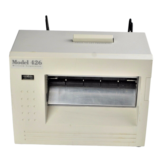
Figure 1 426 Front Angled View
Figure 2 426 Rear Angled View
Introduction
Chapter 1: Printer Specifications
General Specifications
Printing Specifications
Table 1 General Specifications
Table 2 Printing Specifications
Media Specifications
Table 3 Media Specifications
Chapter 2: Features and Options
Fonts
Graphics
Bar Codes
Special Features
Options
Chapter 3: Getting Started
Unpacking and Inspection
Figure 3 Standard Printer Accessories
Connecting the Printer
Printer Power
Communication Interfaces
Figure 4 Connecting the Printer
Loading Media
Figure 5 Tag Bracket
Figure 6 Loading Media
Front Panel Button and Indicator Light
Figure 7 Front Panel Button and Indicator Light
Front Panel Button
Indicator Light
Table 4 Front Panel Button Description
Table 5 Indicator Light Description
Chapter 4: Printer Modes
Idle Mode
Halted Mode
Enquiry Responses
Fatal Error Responses
Table 6 Enquiry Responses
Basic Status Responses
Paused Mode
Diagnostic Mode
Entering Diagnostic Mode
Status Label
Figure 8 ^D960)1 or ^K Test Pattern
Figure 9 ^D323-List Enablements Example
Figure 10 ^D326-List Settings Example
Figure 11 ^D325-List Selections Example
Printer Modes
Figure 12 ^D324-List Statistics Example
Chapter 4 Printer Modes
Chapter 5: Communications
RS-232 Serial
Table 7 RS-232 Cable Configurations
RS-232 Printer Cables
10BASE-T Ethernet
160P Stacker / Auxiliary Interface
Figure 12 426 Interface Connections
Figure 13 Ethernet Port - 10BASE-T
Chapter 6: Maintenance and Adjustments
Maintenance Schedule
Table 8 Recommended Maintenance Schedule
Thermal Printer Card
Figure 14 Insertion of Thermal Cleaning Card
Figure 15 Thermal Card Removal
Figure 16 Removal of Top Cover
Figure 17 Unlatching of Print Head
Internal Cleaning
Figure 18 Internal Cleaning
Print Head Maintenance
Figure 19 Print Head Thermal Elements
Cleaning the Drive Roller
Exterior Cleaning
Gap Detector Adjustment
Figure 20 Gap Detector
Auxiliary Button
Flash Memory Update
Figure 21 Auxiliary Button
MCA Compressed File Recovery
Chapter 7: Troubleshooting
Troubleshooting Tips
Appendix A
Limited Warranty
Appendix B
Return Material Authorization (RMA) Procedure
Glossary
Index
User Notes
Advertisement
Quick Links
1
Connecting the Printer
2
Troubleshooting Tips
Download this manual
MODEL 226 / 426
DIRECT THERMAL PRINTER
USER'S GUIDE
PART NUMBER 880018-0110
Revised: December 13, 2004 CPC
© Copyright 2004 by Microcom Corporation, Lewis Center, Ohio – All rights reserved.
Printed in the United States of America
Table of
Contents
Previous
Page
Next
Page
1
2
3
4
5
Advertisement
Table of Contents
Need help?
Do you have a question about the 226 and is the answer not in the manual?
Ask a question
Questions and answers
Related Manuals for Microcom 226
Printer Microcom 1100 Manual
Label design software (15 pages)
Printer Microcom 424 Operator's Manual
Direct thermal printer (187 pages)
Printer Microcom 224 Quick Manual
Desktop thermal printer (2 pages)
Printer Microcom 224 Operator's Manual
Direct thermal printer (213 pages)
Printer Microcom 238B Operator's Manual
Direct thermal printer (222 pages)
Printer Microcom 426 User Manual
Direct thermal printer (70 pages)
Printer Microcom 326M User Manual
Direct thermal printers (73 pages)
Printer Microcom 400 Operator's Manual
Direct thermal printer (100 pages)
Printer Microcom 324M Operator's Manual
Direct thermal printer (192 pages)
Printer Microcom 412 Operator's Manual
Thermal printer (108 pages)
Printer Microcom 466 Operator's Manual
Thermal transfer printer (99 pages)
Printer Microcom 465 Operator's Manual
Direct thermal / thermal transfer printer (106 pages)
Printer Microcom 470 Operator's Manual
Direct thermal / thermal transfer printer (124 pages)
Printer Microcom 428M Operator's Manual
Direct thermal printer (207 pages)
Printer Microcom 322M Operator's Manual
Direct thermal printer (120 pages)
Printer Microcom 426P Quick Manual
Desktop thermal printer (2 pages)
This manual is also suitable for:
426
Table of Contents
Print
Rename the bookmark
Delete bookmark?
Delete from my manuals?
Login
Sign In
OR
Sign in with Facebook
Sign in with Google
Upload manual
Upload from disk
Upload from URL


Need help?
Do you have a question about the 226 and is the answer not in the manual?
Questions and answers