Table of Contents
Advertisement
Advertisement
Table of Contents

Related Manuals for Avery Dennison ALX 720


Summary of Contents for Avery Dennison ALX 720
- Page 1 Release 4/09 Article number: 0089999-29...
-
Page 3: Table Of Contents
Operators Manual ALX 720 Contents 1. Important Notes......................7 1.1 Overview............................7 1.1.1 Manufacturer........................7 1.1.2 Technical State ........................7 1.1.3 Copyright..........................8 1.2 Safety............................8 1.2.1 General Safety Notes ......................8 1.2.2 Warning Notes in the Text ....................8 2. - Page 4 Operators Manual ALX 720 4.4 Control of dispense unit ......................33 4.4.1 Dispenser Menu selection....................33 4.4.2 Missing label function and web breaks ................33 4.4.3 Display and data input......................33 4.5 Handling the print operation......................37 4.5.1 New Start of Printer......................37 4.5.2 Restart of Printer ......................37 4.5.3 Call of Program Version ....................37...
- Page 5 Operators Manual ALX 720 8. Status messages....................85 8.1 Printer messages........................85 8.2 Dispenser Error Messages ......................91 8.3 Dispenser warnings ........................92 9. Card plug in modules ..................... 95 9.1 Card hardware..........................96 9.2 Memory types ..........................97 9.2.1 PROM card (Programmable Read Only Memory)............97 9.2.2 EPROM card (Erasable Programmable Read Only Memory) .........
-
Page 7: Important Notes
The ALX 720 is available in a right- or a left-hand version. The expression right or left is related to the direction of product transport. In the following, a right hand machine is explained. For the left hand version all explanations have to be mirrored. -
Page 8: Copyright
Operators Manual ALX 720 1.1.3 Copyright © This manual and its contents are protected. Duplications of the manual are allowed only if expressly permitted by the manufacturer. The manufacturer reserves the right to technical and other alterations without prior notice. The publisher cannot warrant the accuracy of the content of this manual. -
Page 9: Description
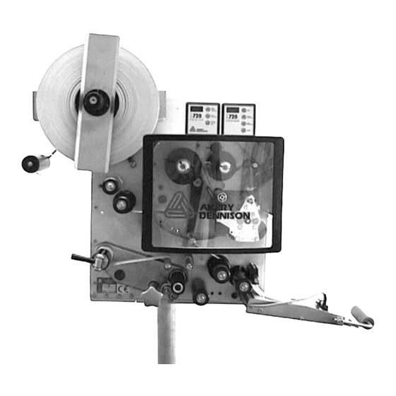
Operators Manual ALX 720 2. Description This chapter explains the structure and the function of the 720 dispenser part. The expressions used are explained here. CAUTION! - The machine is connected to mains. Only authorised personnel may open the cover. Operation without this cover is not allowed. - Page 10 Operators Manual ALX 720 Figure 1 Layout 720 With the handle (015) you may open and close the pressure mechanics (013). When inserting the material the pressure roller has to be opened. Dispensing is only possible when the handle (015) is in the closed position. Via the deviator roller (016) the backing paper is guided to the...
- Page 11 Operators Manual ALX 720 rewind mandrel (017). The cone between the 4 pins can be pulled out to allow the reward backing paper to be removed. Except for the drive roller (001) and the material brush (006) the 720 has no wearing parts. The operator panel (019) is described in the next chapter.
-
Page 12: Operator Panels
Operators Manual ALX 720 2.2 Operator panels There are two operator panels for handling the machine. The operator panel for the dispenser is shown below, it has a 4 digit LED display and 4 membrane keys. Figure 2 Operator panel dispenser... - Page 13 Operators Manual ALX 720 ENTER This key is used to enter or exit a menu point or to cancel a warning or error message. When the keys have different meanings, it will be explained in the relevant menu description. The printer part is equipped with it’s own display – so you can handle the printer and the dispenser completely independent.
-
Page 14: Plug Board
Operators Manual ALX 720 2.3 Plug board On the side a plate contains all plugs for external connections. If you use the optional connections, it is strongly recommended to do this by means of the optional available SUB-D connectors. This ensures best EMI stability of the machine. - Page 15 Operators Manual ALX 720 Applicator plug Product sensor Serial interface dispenser Figure 5 Plugs for dispenser 4/09 Page 15 Description...
-
Page 17: Preparing The Machine
Operators Manual ALX 720 3. Preparing the machine 3.1 Installation 3.1.1 Unpacking of the unit Before removing the unit off the box, don’t hold the machine on the dispensing edge, printer unit to prevent disadjustment off the machine. For mounting the machine, a complete system of holding tools is available. Ask your Avery representative. -
Page 18: Preparing The Dispenser
Operators Manual ALX 720 3.2 Preparing the Dispenser 3.2.1 Inserting material Insert your label material in the machine to follow the instructions in the chapter Operation / Threading. 3.2.2 Defining label data For correct dispenser operation, you have to tell the machine the length of the label and adjust the label sensor. -
Page 19: Label Guide
Operators Manual ALX 720 Label sensor LPIT real leading edge of label Sensor signals Figure 6 Definition of LPIT Manual adjustment of the CONT parameter Remove a label from the backing paper and slide it inside the sensor. Reduce the value with the PRIOR key until the LED switched on. -
Page 20: Dispenser Setup
Operators Manual ALX 720 3.3 Dispenser Setup For adjusting the dispenser function, set the printer to OFF. 3.3.1 Stop position The first step is to adjust the stop position. This is the basic adjustment of the dispense process. Also in case of problems with the machine check if the stop position is okay. -
Page 21: Label Position On The Product
Operators Manual ALX 720 3.3.4 Label position on the product At least adjust the position of the label on the product with the POS function or with the STAD function, if an applicator is in use. 3.3.5 Product data bank Save your setting in one of the product data banks. -
Page 22: Positioning Of Full Size Gap Sensor
Operators Manual ALX 720 Figure 9 Adjustment foil unwind 3.4.2 Positioning of full size gap sensor The unit is equipped with a full size gap sensor. From the minimum label width (25,4 mm) to the maximum the sensor can be moved to the wanted position. -
Page 23: Adjust Position Of Print Head
Operators Manual ALX 720 Full size lower part Full size upper part 3.4.3 Adjust position of print head The zero line of the print head can be varied from 2 - 13 mm of the left material edge CAUTION! - Print head must not be plugged off! Loose screw at centre of print head axle and set print head to required position. -
Page 24: Exchanging The Printhead
Operators Manual ALX 720 thin media / small media medium media / medium thick media / wide media Figure 10 Adjustment print pressure 3.4.5 Exchanging the Printhead CAUTION! - The print head is an electronic module and highly sensitive to static impacts. - Page 25 Operators Manual ALX 720 CAUTION! - Metal objects must never get in contact with the dot line. Do not touch print head at dot line or connectors. For reassembling put the print head on the 180° rotated fixation, positioning is done by means of the 2 upright bolts.
-
Page 27: Operation
Operators Manual ALX 720 4. Operation CAUTION! - Be careful on operation, fingers, hair, clothes, jewellery, etc. may be caught by and get into rotating axles. 4.1 Insert label material CAUTION! - Insertion/exchange of foil and material should be carried out only by especially instructed personal. - Page 28 Operators Manual ALX 720 Switch printer to OFFLINE mode and lift print head by brief pressing of the FEED key. Open front cover. Hang document material in reel holder in a way to ensure unwinding that label in the printer section is on the top.
- Page 29 Operators Manual ALX 720 4/09 Page 29 Operation...
- Page 30 Operators Manual ALX 720 Figure 12 Threading 4/09 Page 30 Operation...
-
Page 31: Threading Of Thermal Transfer Foil
Operators Manual ALX 720 4.2 Threading of thermal transfer foil Attach foil reel onto foil mandrel on the right-hand side for anticlockwise unwinding of foil. Attach empty foil core onto mandrel on left-hand side. Insert foil end diagonally from the front under print-head holder and print head holder with open hinge drive mechanism. -
Page 32: Initialise New Label Material For Dispenser
Operators Manual ALX 720 4.3 Initialise new label material for dispenser The 720 requires data of the label material in use i.e. label length and opacity of the label and backing material. In most cases those parameters can be scanned during automatic initialisation. -
Page 33: Control Of Dispense Unit
Operators Manual ALX 720 4.4 Control of dispense unit 4.4.1 Dispenser Menu selection Turning on the mains switch and at the same time pressing one of the panel keys, you may select between several options: PANEL KEY Function Display message &... - Page 34 Operators Manual ALX 720 Error display: If the display shows e.g. E__XX, the 720 (dispenser) has recognised an error. A warning is shown by W_XX. As soon as the error has been corrected, you may erase the message by pressing the key ENTER and you will get back to the status the machine was in before the error was indicated.
- Page 35 Operators Manual ALX 720 The labelling position is also changed by variation of the product speed. In this case first control you product speed and the dispense speed VELO. Only if both speed matches adjust the position with the POS function.
- Page 36 Operators Manual ALX 720 Dispense speed __________________________________________________VELO The speed value VELO displays the dispensing speed in 0.1 m/min. The product conveyor speed has to be constant to assure accurate labelling. A change of the product speed causes a different position of the label on the product. In case of inaccurate labelling, it should be verified, if the speed of 720 and your product match together.
-
Page 37: Handling The Print Operation
Operators Manual ALX 720 4.5 Handling the print operation 4.5.1 New Start of Printer Connect printer to computer Switch on machine Display: Acknowledge by ON/OFFLINE key Display: The printer is ready to receive data via the interface 4.5.2 Restart of Printer Restart of printer without disconnection of unit by simultaneous operation of all three keys. -
Page 38: Modes Of Operation - Online
Operators Manual ALX 720 4.5.5 Modes of operation - ONLINE ‘FEED’ and ‘NEXT’ simultaneously program or ‘ESC’ ‘FEED’ - ‘NEXT’ and ON/OFFLINE simultaneously RESET ONLINE MODE Display Display function FEED NEXT HV__ energy print head changing with FEED - (less) - Page 39 Operators Manual ALX 720 Printer in stop mode ______________________________________________STOP Measure: start printer again printer is placed in single start mode _______________________________ SNGL Measure: nothing printer is calculating ______________________________________________ WAIT Measure: nothing printer is stopped via HOST _______________________________________ HOST Measure: start printer again...
-
Page 40: Maintenance
Operators Manual ALX 720 4.6 Maintenance Clean print head and feeding roller with cleaning liquor from paper, adhesive and ink deposits at regular intervals. 4.6.1 Cleaning print head CAUTION! - The print head is an electronic module and highly sensitive to static impacts. -
Page 41: Cleaning Of Foil Guiding Parts
Operators Manual ALX 720 Clean print roller with dust-free cloth and cleansing liquor only. Rotate roller stepwise for complete cleaning. CAUTION! - Never use knives or objects with sharp edges for cleaning. The feed roller and the friction rollers are also to be cleaning from time to time. Avoiding any type of contamination in the printing area generally increases performance of the printer and particularly the print head. -
Page 43: Dispenser Adjustment
Operators Manual ALX 720 5. Dispenser adjustment The touch panel keys or the optional interface can change labeller parameters. The last entered parameters are the actual ones the machine works with. Programming via the interface is described in chapter Serial interface. - Page 44 Operators Manual ALX 720 Power On at power on at power on at power on CODE CODE Standard menu Extended menu Product menu Configuration INIT/ON/OFF INIT/ON/OFF INIT/ON/OFF Direct LPIT PD01 DTST INIT/ON/OFF CONT PD02 P_S_ SENS PD03 MACH STOD STOD...
-
Page 45: Standard Menu
Operators Manual ALX 720 5.1 Standard menu Usually this menu is used for labelling. All important parameters can be changed while the machine is running. After turning power on, the standard menu is active, unless the product menu was on before the machine was switched off. - Page 46 Operators Manual ALX 720 Label position ____________________________________________________POS Function: The start position POS defines when the labelling should take place, after the product has passed the product sensor. Changing the value for POS changes the applied label position on the product.
-
Page 47: Extended Standard Menu
Operators Manual ALX 720 5.2 Extended standard menu The extended standard menu offers additional parameters you may use in your application. On quitting this menu the current parameter settings are stored in memory. Further changes are also written into memory. As long as this menu is active, no labelling is possible. By pressing the key FEED, however, single dispense of labels is possible. - Page 48 Operators Manual ALX 720 Display Function Data value APT3 Restart delay 0 ... 5000 ms APT4 Time constant compensation 0 ... 500 ms ASTP End of air stream signal -20 ... 50 mm Printer dwell time OFF - 1000ms Printer hold time (is 50% PDT)
- Page 49 Operators Manual ALX 720 Sensor status ____________________________________________________SENS Function: Status of label sensor is indicated, i.e. there is a label in the sensor the abbreviation LAB is displayed and GAP is shown if there is only backing material inside the label sensor.
- Page 50 Operators Manual ALX 720 Stop position ___________________________________________________ STOD Function: Stop position of the label at the dispensing edge. Available: Always Range: 0.0 ..200.0 mm Product length ___________________________________________________PRDL Function: The product length avoids multi labelling in case of difficult products. Normally it is set to AUTO.
- Page 51 Operators Manual ALX 720 Start delay_______________________________________________________STAD Function: Delay time for the dispensing by means of an applicator after the product has passed the product sensor. This value influences the position of the label on the product. Only available if applicator is used.
- Page 52 Operators Manual ALX 720 Blow on time ____________________________________________________ APT2 Function: Only used when an applicator is necessary. It defines for how long the label is blown onto the product. Available only with applicator. Range: 1 ... 7500 ms Restart delay ____________________________________________________ APT3 Function: This parameter defines the time for a next label dispense after the applicator cycling is completed.
- Page 53 Operators Manual ALX 720 End of air stream signal ___________________________________________ASTP This parameter determines how long the air stream signal will remain active after the label dispense has finished. Valid in all modes (direct dispense, applicator, APSF and fixed-speed). Printer dwell time __________________________________________________ PDT This determines the dwell time of the stamp-printer.
-
Page 54: Configuration Menu
Operators Manual ALX 720 5.3 Configuration menu Adjustments in the configuration menu are necessary during installation of the machine only. In the configuration menu, the required optional functions can be selected. Some service support functions in the configuration menu will be useful for the service staff. -
Page 55: Handling The Menu
Operators Manual ALX 720 5.4 Handling the menu The menu structure is shown in the following table. By means of the key PRIOR you switch to the prior function, and with the key NEXT to the next following function in the menu. -
Page 56: Menu Functions
Operators Manual ALX 720 5.5 Menu functions The menu functions are explained in detail here. Permanent test___________________________________________________ DTST The permanent test makes a test run without using labels. In the display the numbers of dispense cycles is shown (see description LABC). Immediately after starting the function, the machine runs in a self-test. - Page 57 Operators Manual ALX 720 With this function, you can decide how to react: NONE Do nothing. The unlabeled product will be detected later in the line. WARN Set the warning output and displays W__0. The production continued. ERR1 Set the error output to stop the production line immediately and display E_10.
- Page 58 Signal from APSF sensor Ready input stepper motor control Block 2 (inactive = -) I = Inhibit input active Unused input (Loop control on ALX 720) Applicator home switch active Applicator end switch active Horizontal home switch Block 3 (inactive = .)
- Page 59 Operators Manual ALX 720 7 = terminal 31 = READY 8 = terminal 32 = ODC_OUT / HORI_CYL Adjustment resetting ______________________________________________FACT This menu point sets all parameters back to the factory values. All parameters will be reset, so please note all your adjustments before. When you call this function the display shows 'NO`.
- Page 60 Operators Manual ALX 720 Number of data bits _______________________________________________ DBIT The function is only visible if a baudrate is selected. With this function you can select between 7 or 8 data bit protocols. Factory adjustment: 8BIT Recycle (simulates max labels/min) ________________________________ RECY The Auto-recycle function, is used to determine the maximum possible cycle rate with the current parameter settings.
-
Page 61: Product Data Bank
Operators Manual ALX 720 Note: Modified parameter values are only stored if the menu is left by using the QUIT function. If the power is switched off before leaving the menu by quit all modifications are lost. 5.6 Product data bank If parameters have to be changed because of different products and labels, the product menu can be used. -
Page 63: Printer Adjustment
Operators Manual ALX 720 6. Printer adjustment The following page will show you how the structure of the menu is organised! During the OFFLINE mode you adjust different values of the printer or activate and deactivate options. Shown are only the main points of the menu – the lower points you will find easy to understand and operate. -
Page 64: Info: Info Printouts
Operators Manual ALX 720 6.2 INFO: Info printouts In this submenu status prints for tests and output the machine condition could be done. Printout is possible after initialisation of light barrier only. Preferably 200 mm long material of a width of approx. -
Page 65: Prtp: Print Parameter Adjustments
Operators Manual ALX 720 6.3 PRTP: Print parameter adjustments In this submenu the adjustment of the print function is possible. Print Speed ______________________________________________________PSPD The printing speed (material feed) can be adapted to the foil/material combination used to optimise contrast intensity and imprint density of the print. - Page 66 Operators Manual ALX 720 Figure 16 Gap offset Barcode height___________________________________________________ BCHI The barcode height can be multiplied with *1 - *10 mm (factor BCHI). The effective barcode height is calculated on the basis of the value defined in the label layout (mask) multiplied by the enlargement factor BCHI.
- Page 67 Operators Manual ALX 720 Print Offset on X – Axis ___________________________________________ XPOS The mask zero is shifted in relation to the label edge on the X-axis, i.e. transversally to the material. Steps: = 0,25mm „XP.8” = +2mm Maximum (negative) offset from label edge „XP-8“...
-
Page 68: Ifac: Interface Parameter
Operators Manual ALX 720 Example: Self adhesive material with a black bar across the label Measured values: Backing paper Backing paper + label: Backing paper + label + black bar: 190 Value to be adjusted: 60, i.e. all measured values higher than 60 will be ignored, as well the black bar ( = 190) „Auto“... - Page 69 Operators Manual ALX 720 Transmission Speed _____________________________________________ BAUD The transmission speed on the serial line has to be the same selection like on the host. „300“ 300,same for 600,1200,2400,4800,9600,19200 Baud or 38400= “384” Parity ___________________________________________________________ PARI „ODD“Odd parity „EVEN“ Even parity „NONE...
-
Page 70: Sysp: System Parameter
Operators Manual ALX 720 6.5 SYSP: System Parameter Here some general settings are defined. Print Interpreter _________________________________________________ EMUL The interpreter determines the „language“ in which the printer receives and processes data. In Easy-Plug, the commands transmitted are printed as label text. - Page 71 Operators Manual ALX 720 National Character Set ___________________________________________ NACH In accordance with the selected character set, the individual decimal and hexadecimal values are replaced as shown in the table. decimal 35 123 124 125 126 ASCII > 127 (Blank) ≡...
- Page 72 Operators Manual ALX 720 224 / 256 Character Set § ″ & ’ < > ‘ ˜ € ü é â ä à å ç ê ë è ï î ì Ä Å É æ Æ ô ö ò û...
- Page 73 Operators Manual ALX 720 Machine direction _________________________________________________ L-R The machine is available in a right and left hand version. In the right hand version the product transport is from left to right when you look to the front of the machine.
- Page 74 Operators Manual ALX 720 Display (printer mode) Access levels (selection under parameter; CODE) COD0 all functions locked - except password inquiry COD1 Access to ONLINE mode, printing is possible COD2 All functions are accessible OMOD/ONLI After connecting in the ONLINE mode...
- Page 75 Operators Manual ALX 720 Entry of password for authorised access A = NEXT, NEXT, FEED, ON/OFF B = FEED, ON/OFF, NEXT, FEED, FEED Corresponds to authorised access, no entry required Check of entered password Access time An entered password - A or B - is active until reset or re connection of printer...
- Page 76 Operators Manual ALX 720 Real Time Clock _________________________________________________ CLCK Adjusting the real time clock to the current time. This parameter can be activated only if the optional clock is installed. The clock has a life of about 10 years. Leap years are calculated automatically.
-
Page 77: Jclr: Clearance Of Print Job
Operators Manual ALX 720 Material End Recognition _________________________________________ MEND For label material with gaps longer than 15mm resp. material with differing light diffusion permeability (error ST05 = material end, when material is correctly inserted) the material end recognition can be cancelled. - Page 78 Operators Manual ALX 720 The printer is using SLOT0 if a card is found there – if not SLOT1 is used. to format the card. After that a reset takes place. Are two cards used in the printer (one for logos one for fonts) the printer is selecting the cards.
- Page 79 Operators Manual ALX 720 CAUTION! - In case the value without materials is > 5 or with material <10 clean sensor by means of pressure air. If this fails, call service technician. Rxxx Dancer sensor < 85 home position 200-240 end position If this sensor is not installed the display shows „R255“...
-
Page 80: Print Head Temperature
Operators Manual ALX 720 6.9 Print head temperature The print head temperature can be reduced/increased by reduction/increase of the setting value, respectively. An extra bold printing result is obtained with increased heat supply. Optical Features of Temperature Setting Optimal temperature... -
Page 81: Remote Programming
Operators Manual ALX 720 7. Remote programming The machine has a serial interface according to the standard RS232C. Via this interface parameters can be adjusted. All received commands are tested for syntax and legal value range. Invalid commands and parameters are ignored. An error message is not given in this case. -
Page 82: Interface Commands
Operators Manual ALX 720 Factory interface deactivated, at reactivation the parameters will be set to 8 data bits, 2 stop bits and no parity bit. 7.2 Interface commands The below described commands will change one of the labelling parameter. The values are not stored and will be lost when turning off power. - Page 83 Operators Manual ALX 720 Command Description Range #!MACHnnnn Machine type 0000 ALS230 0001 ALX720 0002 ALS330 0003 ALS430 #!MDIRnnnn Motor direction 0000 Right --- > 0001 Left < --- #!MLABnnnn Missing label error 0000 NONE 0001 Warning 0002 Error 1...
-
Page 84: Programming Of Printer Functions
Operators Manual ALX 720 #!SP__ The machine is set to off. The product sensor is disabled and labelling will therefore be stopped. #!SR__ The machine is set to on. The product sensor is enabled and labelling can restart. #!XC Pharmacy Code ackn. -
Page 85: Status Messages
Operators Manual ALX 720 8. Status messages The software checks during the labelling permanently, if the machine runs under normal operation. There are 3 types of messages indicating a problem: STxx: A fault condition of the printer E__x: Labelling of the dispenser is not possible... - Page 86 Operators Manual ALX 720 Problem Meaning How to solve ST05 Material end Depress NEXT key to switch off acoustic signal Depress (FEED) key to acknowledge status message Display: “OFF“ Insert material, check and, in case, correct light barrier position (ON/OFF) key - job is further processed...
- Page 87 Operators Manual ALX 720 Problem Meaning How to solve ST10/11 Check -total error - RAM card Check whether correct RAM card (spooler + logo) is plugged in Reformat card Caution: All data are cleared! • check scanner ST13 Barcode not to read •...
- Page 88 Operators Manual ALX 720 Problem Meaning How to solve ST27 Number overflow (Auto- Check whether numbers exceed 65000 Acknowledgement) or format positions exceeding maximum label dimension are used ST28 Character, line or logo do not fit Change positions accordingly into the physical printing format...
- Page 89 Operators Manual ALX 720 Problem Meaning How to solve ST46 Wrong bar code number Easy Plug: Invalid bar code number within the #YB command. The status message disappears automatically after 3 s. Afterwards, the printer continues printing. The label layout is printed without the relevant bar code.
- Page 90 Operators Manual ALX 720 Problem Meaning How to solve ST71 Error at print head pulse Disconnect and re-connect, in case of management failure call service technician. Caution: Allow for at least 60 seconds between disconnection and re- connection. ST72 Error at generation of print image...
-
Page 91: Dispenser Error Messages
Operators Manual ALX 720 8.2 Dispenser Error Messages In case of an error message the relevant output is switched. The signal can be used for interconnection with an external machine control. STO! Power-fail message The message STO! appears in the display as the machine is switched off or if the mains supply voltage has fallen below specification. -
Page 92: Dispenser Warnings
Operators Manual ALX 720 Message Meaning How to solve close. Increase speed of printer. ___0 Process error (Divide overflow) Hardware failure external noise. EPROM damaged. Turn off power and on again. Change EPROM or main board ___1 Illegal interrupt (processing error) Hardware failure external noise. - Page 93 W__6 Too many products between Move the sensor closer to the sensor and dispensing edge dispensing edge W__7 ALX 720: Loop was empty Increase print speed. If the label is not too long: increase when labelling should start SW02 4/09...
-
Page 95: Card Plug In Modules
Operators Manual ALX 720 9. Card plug in modules These plug in modules are provided for the optional font and logo cards. Use PCMCIA cards up to a size of 2 MB only. There is a maximum of 1 logo card alone or together with a font card –... -
Page 96: Card Hardware
Operators Manual ALX 720 9.1 Card hardware Printer Card type Quantity Memory of PROM S-RAM Flash card type card card card card PCMCIA 2 MB For more information regarding card types please refer to the card manual. Pin34 Pin1 Pin68 Pin35 Figure 17 PCMCIA card pin assignment (left);... -
Page 97: Memory Types
Operators Manual ALX 720 9.2 Memory types 9.2.1 PROM card (Programmable Read Only Memory) Programmable only with a special program unit (EPROM burner) – it is a on time card, normally used to store fonts and logos witch are used again and again in the same shape size or look like. -
Page 98: Card Use
Operators Manual ALX 720 9.3 Card use Depending on the printer type the cards can be used different. Attached you will find a table showing card type, menu point to clear the card – where the card has to be formatted – and as well the quantity of files. -
Page 99: Connections And Signals
Operators Manual ALX 720 10. Connections and signals This machine has a number of inputs to connect sensor’s and a control. Outputs are available for applicators, a printer and other purposes. 10.1 Output signals This machine has eight outputs, which switch the output from open circuit to + 24V. The maximum current must not exceed 500 mA. -
Page 100: Applicator Modes
Operators Manual ALX 720 10.2 Applicator modes The machine is able to dispense the label direct on the passing product. There is also the possibility to drive without any external control a wide range of applicators. 10.2.1 Signals for direct dispense For direct dispensing the airstream signal can be used to control a pneumatic driven dispensing edge. -
Page 101: Control Signals For The Asa Applicator
Operators Manual ALX 720 10.2.2 Control signals for the ASA applicator For controlling an air stream applicator the signals air- stream and blow on are necessary. The time period APT2 defines how long the blow on signal is active. After labelling the product and the time period of APT3 a new label will be dispensed on to the applicator. -
Page 102: Signals For The Ep Applicator
Operators Manual ALX 720 10.2.3 Signals for the EP applicator For controlling the applicator the signals air stream, cylinder valve and blow on are necessary. After a product signal has occurred the labelling cylinder valve is switched active after the delay STAD. -
Page 103: Applicator Connector
Operators Manual ALX 720 10.2.4 Applicator connector The applicator connection is done via a 15 pole D-sub connector common to other machines. Figure 21 Applicator connector 4/09 Page 103 Connections and signals... -
Page 104: Input Signals
Operators Manual ALX 720 10.3 Input signals This machine (dispenser) is provided with photo coupled inputs for: the product sensor signal an inhibit signal for inhibiting labelling a signal from an OD control which shows the end of the material roll. -
Page 105: Product Sensor
Operators Manual ALX 720 10.3.1 Product sensor The product sensor starts the labelling. The source of the signal could be a optical sensor, a switch or a signal from a PLC. The time between start signal and start of dispensing (adjusted with POS) should be as small as possible. -
Page 106: Od Control Sensor
Operators Manual ALX 720 10.3.2 OD Control sensor Optional an OD control could be mounted to control the label roll. If the label material is nearly empty the sensor gives an signal. A warning message and an output signal inform the personal that in the next time the material has to be changed. -
Page 107: Apsf Sensor
Operators Manual ALX 720 10.3.3 APSF sensor For the APSF function (Automatic speed follower) a rotary encoder has to be installed. For optimum labelling accuracy the rotary encoder should be selected so that it produces one pulse for every 0.125 mm of product movement. The connection of the encoder should be done with a shielded cable. -
Page 108: Control Signals
Operators Manual ALX 720 10.3.4 Control signals An optional connector could be installed for integration of the machine in the line control. Inhibit + Startunterdrückung + white weiß +24 Volt +24 Volt Inhibit - Startunterdrückung - blue blau Error output... - Page 109 Operators Manual ALX 720 Figure 30 Internal I/O connector 4/09 Page 109 Connections and signals...
-
Page 110: Emi
Operators Manual ALX 720 10.4 EMI To protect the machines against electrical noise and to protect production of electrical noise you have to follow this rules: Rule 1 All metallic parts must have a good and plane contact (no lacquer, aluminium oxide is an isolator). -
Page 111: Electronic Diagrams
Operators Manual ALX 720 10.5 Electronic diagrams Figure 31 Block diagram ALX 720 4/09 Page 111 Connections and signals... - Page 112 Operators Manual ALX 720 Figure 32 Layout dispenser electronic board 4/09 Page 112 Connections and signals...
- Page 113 Operators Manual ALX 720 48VAC 48VAC Phase1A Phase1B Phase2B + Richtung - Richtung + Takt - Takt 800 Schr Schrittauflösung + NC - NC Bereit Collector 400 Schr Bereit Emitter Bereit LED Übertemperatur 100% on LED Über-/Unterspannung Überstrom 25% on / 75% off...
- Page 114 Operators Manual ALX 720 Figure 35 CPU board 4/09 Page 114 Connections and signals...
- Page 115 Operators Manual ALX 720 Figure 36 Connectors I/O board 4/09 Page 115 Connections and signals...
- Page 116 Operators Manual ALX 720 Figure 37 Adjustment I/O board 4/09 Page 116 Connections and signals...
-
Page 117: Technical Specification
Operators Manual ALX 720 11. Technical specification Description Details Label width 25,4 mm – 100 mm (incl. backing paper) Label length 5 to 330 mm Roll with max. outer ∅ 300mm, Label roll core ∅1.5" (37 mm), 3" (75 mm) or 4” (100 mm) with optional adapter rings. - Page 118 Operators Manual ALX 720 Description Details Interfaces Standard: serial RS 232 Optional (alternatively): serial RS 485 Plug-in cards 2 Slots (PCMCIA) with each 2 MB Memory, 1MB dynamic RAM Label sensor printer Self initialising infrared gap sensor; Adjustment range 12 – 98 mm;...
- Page 119 Operators Manual ALX 720 Application specification The labeller is designed and built for automatic apply of self-adhesive labels. Advise for security In order to avoid any risk of injury due to squeezing between the fixed dispensing edge and the passing product, it may be necessary to add a protection cover in front of the dispensing edge.
-
Page 120: Label Material
Operators Manual ALX 720 11.1 Label Material The printer is equally suitable for thermal transfer printing. Three factors are to be taken into account when choosing the material: Abrasive behaviour of the surface structure Properties with respect to chemical reaction on print-colour transfer Temperature required for colour- transfer If the material is extremely abrasive, the print head is faster worn as usual. -
Page 121: Adjustment
Operators Manual ALX 720 12. Adjustment 12.1 Printer Function Factory Application PSPD PS 8 (ips) MLEN L 25 (mm) MWID W107 (mm) PUNO BCHI UPCA XPOS XP 0 YPOS YP 0 SSPD SS 8 (ips) AUTO PORT RS23 SPOL 64KB... -
Page 122: Dispenser
Operators Manual ALX 720 12.2 Dispenser Function Factory Application P_S_ LEDG MACH MDIR RAMP FAST MLAB WARN COMP APSF APPL BAUD NONE PARI SBIT 2BIT DBIT 8BIT DIST 76.0 mm SLEW FAST 4/09 Page 122 Adjustment... - Page 123 Operators Manual ALX 720 Function Factory PD01 PD02 PD03 PD04 POS(STAD) 100.0 mm VELO 30.0 m/min STOD 76.0 mm BLOW(APT2) 1 ms LPIT AUTO CONT AUTO PRDL AUTO EGRA APT1 200 ms APT3 0 ms APOS ASTP Function PD05 PD06...
-
Page 124: Index
Operators Manual ALX 720 13. Index applicator ........101, 103 MACH ......Siehe Machine type Applicator..........57 Machine type ........... 56 APSF ......... 55, 57, 107 Memory types .......... 97 ASA ............101 missing label ..........56 Automatic product speed follower..Siehe APSF NONE ............
Need help?
Do you have a question about the ALX 720 and is the answer not in the manual?
Questions and answers