Table of Contents
Advertisement
Quick Links
Advertisement
Table of Contents
Troubleshooting

Related Manuals for Avery Dennison ALS 341


Summary of Contents for Avery Dennison ALS 341
- Page 1 ALS 341 User Manual ...Covering the World Release 4/04 Part number 0089999-10...
-
Page 3: Table Of Contents
Operators Manual ALS 341 Contents 1. Important Notes......................1 1.1 Overview............................1 1.1.1 Manufacturer........................1 1.1.2 Copyright..........................1 1.2 Safety notes..........................2 General Safety Notes ........................2 Warning Notes in the Text ......................2 1.2.1 Operator’s duty of care ...................... 3 1.2.2 Concrete security regulations and symbols used .............. - Page 4 Operators Manual ALS 341 5. Messages and Troubleshooting ................27 5.1 Warnings .............................27 5.2 Error messages...........................28 5.2.1 Processor error ........................29 5.3 Trouble shooting .........................29 6. Electrical connections .................... 31 6.1 Power supply ..........................31 6.2 Location of the electronic control boards ..................32 6.3 Stepper motor control .........................33...
-
Page 5: Important Notes
AVERY and all other related brands and product names are trademarks of Avery Dennison Corporation. No licence to use or reproduce any of these trademarks or other trademarks of Avery Dennison Corporation is given or implied. All other brand and product names are the trademark of their respective owners. -
Page 6: Safety Notes
Operators Manual ALS 341 1.2 Safety notes General Safety Notes Warning Notes in the Text In this description, two types of notes can be found: Warning note – indicates a possible risque of injury for the user. Ignoring the warning can lead to injuries or material damages. -
Page 7: Operator's Duty Of Care
Operators Manual ALS 341 1.2.1 Operator’s duty of care The machine was designed and constructed taking into account a hazard analysis and after careful selection of the harmonised standards to be observed, as well as other technical specifications. Thus, it corresponds to the state of the art and allows the highest possible degree of safety during operation. -
Page 8: Concrete Security Regulations And Symbols Used
Operators Manual ALS 341 1.2.2 Concrete security regulations and symbols used In the following operating instructions, concrete security regulations are indicated in order to point out the remaining risks which cannot be avoided when operating the machine. These remaining risks include danger to •... -
Page 9: Security Measures During Normal Operation
Operators Manual ALS 341 1.2.3 Security measures during normal operation The machine may only be operated by trained and authorised persons who are familiar with the operating instructions and are able to work in accordance with it! • Before starting the machine, check and make sure that •... -
Page 10: Work On The Electrical Equipment
Operators Manual ALS 341 1.2.5 Work on the electrical equipment Repair work on the electrical equipment of the machine may only be performed by a trained electrician! Electrical equipment must be checked on a regular basis! Loose connections must be fixed again! - Page 11 Operators Manual ALS 341 Release 4/04 Page 7...
-
Page 13: Short Form Instruction
Operators Manual ALS 341 2. Short form instruction This chapter contains a short instruction to handle the machine. CAUTION! - The machine is connected to mains. Only authorised personnel may open the cover. Operation without this cover is not allowed. -
Page 14: Service Menu
Operators Manual ALS 341 will be placed closer to the front side of the product. The possible variation of the value is 10mm up to 999.9mm. Contrast: This function adjusts the sensitivity of the standard optical label sensor. If the function is called, the display shows maybe CX30. - Page 15 Operators Manual ALS 341 Leave service menu: Press Contrast key until QUIT is displayed, then press Contrast key again. Release 4/04 Page 11 Short form instruction...
-
Page 16: Starting The Labeller
Operators Manual ALS 341 3. Starting the labeller In this chapter, the steps to prepare the machine will be described. 3.1 Installation 3.1.1 Unpacking of the unit • For removing the unit off the box, don’t hold the machine on the dispensing edge to prevent disadjustment off the machine. -
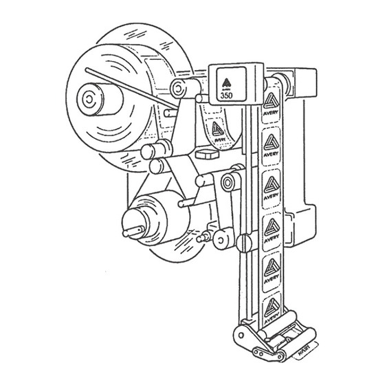
Page 17: Mounting A New Label Roll
Operators Manual ALS 341 3.2 Mounting a new label roll The threading path of the labelling material through the labeller is shown in the diagrams below. A threading diagram is also affixed to the machine’s front-plate for easy reference. Figure 2 Threading diagram Type 341... - Page 18 Swing the retainer arm away from the unwind mandrel and take off the old label roll. Push the new label roll onto the unwind mandrel. Swing the retainer arm back onto the unwind mandrel Figure 5 Unwind ALS 341 After threading the backing paper around the roller and shaft of the dancer-arm next to the rewind mandrel, insert the edge of the backing paper into the slot of the rewind mandrel and clamp it there by turning the lever.
-
Page 19: Setting The Applicator Roller
Operators Manual ALS 341 Adjust the pressure rollers so that they are positioned over the middle of the material. Adjust the brush so that it applies no more pressure to the label web than is necessary to keep it tight during dispensing. -
Page 20: Adjustment Of The Contrast
Operators Manual ALS 341 Figure 8 Adjustable dispensing edge Adjustment dispensing edge After loosening handles 1 and 2, handle Z can be turned to adjust the dispensing edge position. Once the adjustment is completed, tighten the handles 1 and 2 again. -
Page 21: Capacitive Label Sensor
Operators Manual ALS 341 3.5.1 Capacitive label sensor For transparent labels the standard photo label sensor doesn’t work. In this case, use a mechanical or a capacitive label sensor. For correct automatic initialisation, the contrast setting has to be set to any value, if you using not the standard photo sensor. -
Page 22: Label Guide
Operators Manual ALS 341 3.6 Label guide On some of the axles, they’re guiding clamps. Adjust the clamps near the machine so all have the same distance to the front plate (31.5mm). The outer clamps should be mounted that the guide but not bend the label material. -
Page 23: Labelling Speed
Operators Manual ALS 341 3.7.2 Labelling speed Set Position to the distance between start sensor and dispensing edge. If installed remove the roller to press the label onto the product. Now try to dispense one product. If the label has wrinkles reduce the speed with the Speed down key. -
Page 24: Operation
Operators Manual ALS 341 4. Operation The operator panel allows an easy operation of the machine. There are 4 functions to operate the machine. In the service menu, the service technician has the possibility to configure the labeller according to your application. -
Page 25: Service Menu
Operators Manual ALS 341 Contrast: Setting the sensitivity of the label sensor. Display: CX00 up to CX63. The X indicates the detection of label material in the sensor. 4.2 Service menu The service menu contains function to configure the machine and check functions. -
Page 26: Menu Functions
Operators Manual ALS 341 4.2.3 Menu functions The service menu contains these functions: Polarity product sensor ___________________________________________ P_S_ This parameter inverts the switching logic of the product-sensor input. This can be used to trigger the product sensor input on either the leading edge or trailing edge of the product. - Page 27 Operators Manual ALS 341 Product length ___________________________________________________PRDL This parameter defines the length of the product to be labelled. After the product-sensor has detected the edge of the product all further signals from the product-sensor are inhibited. This parameter can be helpful in cases where the product is transparent or has several detection marks or edges.
- Page 28 Operators Manual ALS 341 Motor direction___________________________________________________ MDIR This parameter is used to specify the running direction of the labeller's motors. Possible values are "<---" and "--->" to suit a left-hand or right-hand machine respectively. This parameter is already set at the factory.
- Page 29 Operators Manual ALS 341 Test of the optocoupler outputs Press FEED, Display shows XXXX 0 indicates that relevant output is not switched. 1 indicates that the output is active. CN6 pin 26/27 Ready output Press FEED for toggle CN6 pin 23/24...
- Page 30 Operators Manual ALS 341 Label count_____________________________________________________ LABC This parameter is used to show how many labels have been dispensed by the labeller since installation. The number of labels dispensed is displayed in the format: Mnnn Knnn .nnn where M represents millions K represents thousands .represents units...
-
Page 31: Messages And Troubleshooting
Operators Manual ALS 341 5. Messages and Troubleshooting The control checks continuously the status of the machine. If something goes wrong, relevant messages are displayed and simultaneously an output signal is supplied. This output signal can be used as a control signal to an external control. -
Page 32: Error Messages
Operators Manual ALS 341 5.2 Error messages For most of these errors, the labeller can not operate until the cause of the error is removed. The labeller stops operating and a signal is supplied at the error output. You may restart the labeller by pressing the ENTER key once you have cleared the error situation. -
Page 33: Processor Error
Operators Manual ALS 341 5.2.1 Processor error If the processor detect an illegal condition one of the following error messages will be displayed. The machine stops immediately. The ready output is switched off. ER-U An undefined interrupt was requested. ER-I Illegal processor instruction. -
Page 35: Electrical Connections
Operators Manual ALS 341 6. Electrical connections WARNING! - The machine is connected to mains. Only authorised personnel may open the cover. Disconnect from the mains before opening the covers. Operation without cover is not allowed. 6.1 Power supply Select the line voltage on the transformer so that the voltage for the stepper motor driver not exceeds 110 VAC. -
Page 36: Location Of The Electronic Control Boards
Operators Manual ALS 341 6.2 Location of the electronic control boards Figure 13 Electrical components Position Description Order no. Operator Panel 0008576-01 Mains screw terminal 0009305-01 AC-motor control board for rewind motor 0008566-01 Main switch 0001510-05 Rewind sensor 0008257-01 24 V rectifier board... -
Page 37: Stepper Motor Control
Operators Manual ALS 341 6.3 Stepper motor control Jumper for current selection Jumper for resolution Voltage fault 5,6A 200 Schr Ready 110VAC 110VAC Phase1 Phase1 Phase2 Phase2 + Direction - Direction Jumper for current setting + Clock - Clock + Boost... -
Page 38: Cpu - Board
Operators Manual ALS 341 6.4 CPU - board The LED’s of CPU-board indicated the following functions: error output active (only valid if a minimum load of 10kΩ on all outputs of CN10) 24 V in order 12V in order 5V in order... -
Page 39: Display
Operators Manual ALS 341 +12V CN19 +12V PC921 5..20mA Figure 16 Label sensor 6.5 Display All jumpers have to be in the upper position. Release 4/04 Page 35 Electrical connections... -
Page 40: Description Of I/O Signals
Operators Manual ALS 341 6.6 Description of I/O signals The external I/O signals are connect to the terminal on the CPU board Figure 18. All input are electrically separated by opto couplers. NPN and PNP sensor output can be connected shown in Figure 17. - Page 41 Operators Manual ALS 341 Pneumatic-Edge This signal is active, if a label is dispensed. Motor run The signal is active if the dispense motor is running. OD-output The output is active, if the OD-input is active. Release 4/04 Page 37...
- Page 42 Operators Manual ALS 341 Loopsensor Schlaufensenor Ready betriebsbereit Warningoutput (*) Warnausgang (*) Erroroutput Fehlerausgang Printeroutput Druckerausgang inhibit Startunterdrückung OD-control in (*) Eingang OD Kontrolle (*) Material end Materialende CPU - Board Clear error (*) Fehler löschen (*) +24V Printeroutput (*)
-
Page 43: Emi
Operators Manual ALS 341 Ready Productstart Inhibit Product Output PRDL CN10 / 6 Dispense Dispensing edge APOS Output CN10 / 8 Printer Output PDWT CN10 / 10 CN6 / 19 Productstart disabled. PRDL activ Missing Label: New start of dispense during printer activ Inhibit activ Machine not ready. - Page 44 Operators Manual ALS 341 Rule 5 On all inductive components (relays, valves) must be directly connected a clamp circuit (diode, MOV). Rule 6 All signal lines must be shielded. The shield must have a good earth connection on both sides.
-
Page 45: Maintenance
Operators Manual ALS 341 7. Maintenance The labeller has a minimum of movable parts, which ensures a minimum of maintenance required. 7.1 Cleaning A weekly check of the following is recommended: 1. Clean all rollers from glue and labels. Use a solvent or alcohol 2. - Page 46 Operators Manual ALS 341 Figure 20 Rewind adjustment Release 4/04 Page 42 Maintenance...
-
Page 47: Technical Specification
Operators Manual ALS 341 8. Technical Specification Label width ( incl. backing paper) 10 - 1552 mm Label length Min. 16 mm, max. 250 mm at max speed, 350 mm at lower label rates per minute rate – average speed should not exceed 50% of labelling speed. -
Page 48: Application Specification
Operators Manual ALS 341 8.1 Application specification The labeller is designed and built for automatic applying of self-adhesive labels. 8.2 Advice for security In order to avoid any risk of injury due to squeezing between the fixed dispensing edge and the passing product, it may be necessary to add a protection cover in front of the dispensing edge. -
Page 49: Index
Operators Manual ALS 341 9. Index Motor direction capacitve label P_S_ See Product sensor polarity PRDL See Product length Printer 15, 24, 34 DTST Product length Product sensor 21, 23, 34, 39 Polarity LABC Label length label sensor 14, 21, 32, 39, 41... -
Page 50: Ce Declarations
10. CE Declarations... - Page 51 85385 Eching Wir erklären in alleiniger Verantwortung, daß das Produkt Produktart: Etikettiermaschine Maschinenbezeichnung: Etikettenspender Maschinentyp: ALS 341 Seriennummer: 09250-0x-xxxx mit den folgenden Normen und normativen Dokumenten übereinstimmt 89/392/EWG Maschinenrichtlinie geändert durch: 91/368/EWG; 93/44/EWG; 93/68/EWG Hierfür wurden nachstehende harmonisierte Normen angewandt...
-
Page 52: Declaration Of Conformity
We declare under our exclusive responsibility that the product Product: Labelling machine Type of product: Labeller Machine name: ALS 341 Serial number: 09250-0x-xxxx is in conformity with the following standards: 89/392/EWG Machinery directive changed by: 91/368/EWG; 93/44/EWG; 93/68/EWG and the below mentioned documents have been applied:... - Page 53 Nous déclarons sous notre seule responsabilité que le produit Produit: Machine d'étiquetage Type de produit: Etiqueteuse Nom de la machine: ALS 341 No. de série: 09250-0x-xxxx est en conformité avec les normes suivantes: 89/392/EWG Directives machinerie révision: 91/368/EWG; 93/44/EWG; 93/68/EWG et que les documents mentionnés ci-dessous ont été...
- Page 54 EN 50081-1 and EN 50082–2 Generic immunity standard Opmerkingen en beperkingen : Deze conformiteitsverklaring geldt uitsluitend voor de ALS330 en niet voor machines die in combinatie met de ALS 341 worden gebruikt of geinstalleerd, of eraan worden gekoppeld. Indien de ALS 341 deel uitmaakt van een groter machinesysteem, i.e.
Need help?
Do you have a question about the ALS 341 and is the answer not in the manual?
Questions and answers