
Related Manuals for Trane Tracer AH540


Summary of Contents for Trane Tracer AH540
- Page 1 Setup and Operation ™ Tracer AH540/541 Version 2 Air-Handler Controller CNT-SVX05B-EN...
- Page 3 Setup and Operation ™ Tracer AH540/541 Version 2 Air-Handler Controller CNT-SVX05B-EN April 2004...
- Page 4 CNT-SVX05B-EN...
- Page 5 Although Trane has tested the hardware and software described in this guide, no guarantee is offered that the hardware and software are error free. Trane reserves the right to revise this publication at any time and to make changes to its content without obligation to notify any per- son of such revision or change.
- Page 6 NOTICE: Warnings and Cautions appear at appropriate sections throughout this manual. Read these carefully: WARNING Indicates a potentially hazardous situation, which, if not avoided, could result in death or serious injury. CAUTION Indicates a potentially hazardous situation, which, if not avoided, may result in minor or moderate injury. It may also be used to alert against unsafe practices.
-
Page 7: Table Of Contents
Contents Chapter 1 Overview and specifications ....1 Configuration options ........1 Communication with other controllers. - Page 8 Contents Zone sensors ..........28 Space temperature measurement.
- Page 9 Contents Two-pipe changeover ........53 Entering water temperature sampling .
- Page 10 Contents Required inputs for unit operation ......88 Diagnostics ..........89 Resetting diagnostics .
-
Page 11: Chapter 1 Overview And Specifications
The functionality of the factory-installed Tracer AH540 controller is iden- tical to that of the field-installed Tracer AH541 controller. This document refers to both versions of the controller as “the Tracer AH540/541” or “the controller” unless a distinction needs to be made between the two. - Page 12 Chapter 1 Overview and specifications Table 1. Tracer AH540/541 air-handling unit configuration options Options Unit configuration Preheat Cool Reheat Heating only • Steam coil • Hydronic heats coil • Electric heat • Face-and-bypass hydronic heat- Cooling only • Hydronic cooling •...
-
Page 13: Communication With Other Controllers
Communication with other controllers Communication with other controllers Tracer AH540/541 controllers operates either in stand-alone mode or as part of a building automation system. In either mode of operation, multi- ple controllers can be bound (bindings are configured using the Rover ser- ®... -
Page 14: Controller Circuit Boards
The main controller board is the same for both Tracer AH540 and Tracer AH541 (see Figure 1), but the termination boards are different (see Figure 2 on page 5 for Tracer AH540 and Figure 3 on page 6 for Tracer AH541). - Page 15 Communication with other controllers Figure 2. Tracer AH540 termination board Analog inputs: AC power IN1–IN6 Comm5 terminals Analog outputs: AO1–AO5 Not used Duct static pressure Not used Binary outputs: BO1–BO6 Not used Binary inputs: IN7–IN12 CNT-SVX05B-EN...
-
Page 16: Chapter 1 Overview And Specifications
Chapter 1 Overview and specifications Figure 3. Tracer AH541 termination board Common terminals Signal terminals BO1 Supply fan start/stop BO2 Exhaust fan start/stop DX cooling stage 1 or electric heat stage 4 DX cooling stage 2 or electric heat stage 3 DX cooling stage 3 or electric heat stage 2 DX cooling stage 4 or electric heat stage 1 AO1 Supply fan speed... -
Page 17: Specifications
8 in. 2 in. × × (140 mm 203 mm 51 mm) • × × Termination boards Tracer AH540: 3½ in. 8 in. 1 in. (89 mm 51 mm) • × × × × Tracer AH541, frame-mounted: 10¼ in. 8 in. - Page 18 Chapter 1 Overview and specifications Figure 4. Power requirements Line voltage 24 Vac Termination board Transformer Main controller board CNT-SVX05B-EN...
-
Page 19: Chapter 2 Operator Display
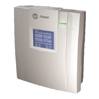
Chapter 2 Operator display This chapter shows how to: Install a Tracer AH540/541 stand-alone operator display • Connect a portable operator display to a Tracer AH540/541 controller • Set up the operator display • Installing the stand-alone operator display With the attached cable, the stand-alone operator display (see Figure 5) can be mounted up to 10 ft (3 m) from the Tracer AH541 controller. - Page 20 Chapter 2 Operator display To install the stand-alone operator display: 1. Unsnap the gray plastic backing from the operator display. 2. Carefully disconnect the operator-display cable from the connector inside the operator display. 3. Use the plastic backing as a template to mark the position of the four mounting holes on the mounting surface (see Figure 6 on page 10).
-
Page 21: Connecting The Portable Operator Display
Connecting the portable operator display Figure 7. Operator-display connector on the Tracer AH541 Operator-display connector Connecting the portable operator display The portable operator display is designed for temporary connections to Tracer AH541 controllers. It can be hot-swapped. CAUTION Avoid Equipment Damage! To clean the operator display, use a cloth dampened with commercial liquid glass cleaner. -
Page 22: Setting Up The Operator Display
• The controller location label: When no location is specified and the • controller is a Tracer AH540, “Tracer AH540” is displayed. When no location is specified and the controller is a Tracer AH541, “Warning: Unit Config Required” is displayed. -
Page 23: Calibrating The Operator Display
Setting up the operator display 2. Press the down arrow button to go to page 2 of 2. 3. Press the Change Date button to view the next screen. 4. Press the forward and back arrows to move the cursor from day to month to year. -
Page 24: Setting Up, Changing, Or Disabling The Security Password
Chapter 2 Operator display 6. To increase the contrast, press the buttons along the bottom row, in sequence, from left to right. To decrease the contrast, press the buttons from right to left. 7. Press the Home button. The home screen appears. Setting up, changing, or disabling the security password To set up or change a security password or to disable its use:... -
Page 25: Chapter 3 Input And Outputs
Input and Outputs This chapter provides information about the function of inputs and out- puts of the Tracer AH540/541 controller. The Tracer AH540 is configured at the factory per unit configuration and order information. The field- installed Tracer AH541 must be configured using a Rover service tool (refer to the Rover Operation and Programming guide, EMTX-SVX01E-EN, for more information). -
Page 26: Analog Outputs
Supply fan start/stop relay Each binary output has a green status LED on the Tracer AH540/541 con- troller board (see Figure 1 on page 4). The LED is off when the relay con- tacts are open. The LED is on when the relay contacts are closed. -
Page 27: Analog Inputs
Analog inputs Analog inputs The Tracer AH540/541 controller has eight analog inputs. Table 5 describes the function of each of the analog inputs. Each function is described in the following paragraphs. For an explanation of the diagnos- tics generated by each input, see Chapter 6, “Verifying operation and communication.”... -
Page 28: In1: Space Temperature
IN1: Space temperature Analog input IN1 measures space temperature only. The space tempera- ture is measured with a 10 kΩ thermistor that is included with Trane zone sensors. The Tracer AH540/541 receives the space temperature from either a wired zone sensor or as a communicated value. A communicated value has precedence over a locally wired sensor input. -
Page 29: In3: Fan Mode Switch
By measuring this resis- tance, the controller determines the requested fan mode. See Table 6. If the Tracer AH540/541 controller does not receive a hard-wired or com- municated request for fan mode, the unit recognizes the fan input as Auto. -
Page 30: In6: Mixed-Air Temperature
The Tracer AH540/541 controller does not allow economizing if the con- troller does not sense a valid mixed-air temperature input. If the sensor returns to a valid input, the controller automatically checks to see if econ- omizer operation is possible. - Page 31 Analog inputs where 20 mA is equal to 100% relative humidity (see Table 76 on page 107). A space relative humidity input is required for space dehumidification control. If valid space relative humidity input does not exist, space dehu- midification control will be disabled. The controller will accept a valid hard-wired sensor input or a communicated value for space relative humidity.
-
Page 32: J43: Duct Static Pressure
The Tracer AH540/541 controller, if configured for variable-air-volume control, cannot operate without a valid duct static pressure input. When the sensor returns to a valid input, the controller resumes unit operation. -
Page 33: On/Cancel Buttons On The Zone Sensor
120 minutes. You can adjust the number of minutes the Tracer AH540/541 is placed in the occupied bypass mode by using the Rover service tool. The controller... -
Page 34: In7: Low-Temperature Detection Or Coil Defrost
When configured as a low-temperature detection input, IN7 protects the coils of hydronic units. A low-temperature-detection device (freezestat) connected to the input detects the low temperature. The Tracer AH540/ 541 controller can protect the coil using one binary input. When the con-... -
Page 35: In8: Run/Stop
Normally open Stop IN9: Occupancy or generic The Tracer AH540/541 controller uses the occupancy binary input IN9 for two occupancy-related functions or as a generic binary input. Local occupancy mode request For controllers not receiving a communicated occupancy mode request, the local occupancy binary input determines the unit occupancy based on the hard-wired signal (see Table 11 on page 25). -
Page 36: In10: Supply Fan Status
IN10: Supply fan status The fan status binary input IN10 indicates the presence of air flow through the supply fan of an air-handling unit. For Tracer AH540/541 applications, a differential pressure switch detects fan status, with the high side of the differential being supplied at the unit outlet and the low side supplied inside the unit. -
Page 37: In12: Exhaust Fan Status Or Coil Defrost
When configured as an exhaust fan status binary input, IN12 indicates the presence of air flow through an exhaust fan associated with the con- trolled air-handling unit. For Tracer AH540/541 applications, a differen- tial pressure switch detects exhaust fan status, with the high side of the differential being supplied at the outlet. -
Page 38: Zone Sensors
Service pin message request • Space temperature measurement Trane zone sensors use a 10 kΩ thermistor to measure the space temper- ature. Typically, zone sensors are wall-mounted in the room and include a space temperature thermistor. A valid space temperature input is required for the controller to operate in space temperature control. -
Page 39: On/Cancel Buttons
(See the Rover Operation and Programming guide, EMTX-SVX01E-EN, for more information). Zone sensor wiring connections Typical Trane zone sensor wiring connections with a fan mode switch are as follows: 1: Space temperature •... - Page 40 Chapter 3 Input and Outputs 5: Communications • 6: Communications • Typical Trane zone sensor wiring connections without a fan mode switch are as follows: 1: Space temperature • 2: Common • 3: Setpoint • 5: Communications • 6: Communications •...
-
Page 41: Chapter 4 Sequence Of Operation
The factory default settings are also based on the air-handling unit configuration and order information. Control modes The Tracer AH540/541 controller is configurable to operate in one of two air-handling temperature control modes: Space temperature control •... -
Page 42: Control Gains
Auto, the controller compares the active space set- point and the active space temperature and decides if the space needs heating or cooling. The Tracer AH540/541 controller must have a valid space temperature and discharge air temperature input to operate space temperature con- trol. - Page 43 Enabled Disabled Disabled Disabled Enabled 1 Enabled means the operation is normal. Disabled means that the controller cannot use the request. 2 The Tracer AH540/541 controller does not support emergency heat. The controller will treat emergency heat as Auto. CNT-SVX05B-EN...
- Page 44 Auto mode, the unit switches to the desired mode based on the control algorithm. If the Tracer AH540/541 controller is operating space temperature con- trol, it uses the space temperature and space temperature setpoint to automatically determine heat or cool mode of operation.
-
Page 45: Cooling Operation
The heating and cooling space setpoint high and low limits are always applied to the occupied and occupied standby setpoints. During the cool- ing mode, the Tracer AH540/541 controller attempts to maintain the active space temperature at the active space cooling setpoint. Based on... -
Page 46: Heating Operation
The space temperature setpoint can be communicated either by a build- ing automation system or peer-to-peer using a binding (see “Communica- tion with other controllers” on page 3). When the Tracer AH540/541 is in occupied mode, occupied standby mode, or occupied bypass mode, a com- municated setpoint takes precedence over a local (hard-wired) setpoint. - Page 47 Space temperature control For example, assume the controller is configured with the following default setpoints: • Unoccupied cooling setpoint 85°F (29.4ºC) Occupied standby cooling setpoint 76°F (24.4ºC) • Occupied cooling setpoint 74°F (23.3ºC) • Occupied heating setpoint 70°F (21.1ºC) • Occupied standby heating setpoint 66°F (18.9ºC) •...
-
Page 48: Discharge Air Temperature Control
Figure 11 shows the steps the Tracer AH540/541 controller takes to con- trol discharge air. First the controller determines if a communicated dis- charge-air heating setpoint and discharge-air cooling setpoint are present. -
Page 49: Heating/Cooling Mode Control
Discharge air temperature control See Table 16 and Table 17 for an example of how the controller deter- mines the effective discharge air temperature setpoint. Table 16. Example of configuration parameters Discharge-air cooling setpoint 55ºF (18.2ºC) Maximum discharge-air cooling setpoint 68ºF (20.0ºC) Minimum discharge-air cooling setpoint 50ºF (10.0ºC) -
Page 50: Power-Up Sequence
Chapter 4 Sequence of operation Auto mode A communicated request of Auto or the controller default operation (Auto) can place the unit into cooling mode. A zone temperature input is required for discharge air temperature control when auto heat/cool changeover is desired. When the controller automatically determines the heating or cooling mode using auto mode, the unit switches to the desired mode based on the control algorithm and the relationship between zone temperature to the configured daytime warm up start and stop setpoints. -
Page 51: Occupancy Modes
• Occupied mode The occupied mode is the normal operating mode for occupied spaces or daytime operation. The Tracer AH540/541 controller operates this sequence according to the configured control mode. Space temperature control: Occupied mode If configured for space temperature control, the controller attempts to... -
Page 52: Occupied Standby Mode
Off whenever the space temperature is between the unoccupied heating and cooling setpoints. If the space temperature rises above the unoccupied cooling setpoint the Tracer AH540/541 turns On the supply fan and provides cooling at the unoccupied cooling setpoint. -
Page 53: Occupied Bypass Mode
Bypass to the controller or by using the timed override but- ton on the Trane zone sensor. When the controller is in unoccupied mode, you can press the button on the zone sensor to place the controller into occupied bypass mode for the duration of the bypass time (typically 120 minutes). -
Page 54: Determining The Occupancy Mode
Occupancy binary input The Tracer AH540/541 controller uses the occupancy binary input IN9 for two occupancy-related functions. For controllers not receiving a communi- cated occupancy request, the occupancy binary input determines the occupancy of the unit based on the hard-wired signal. - Page 55 The hard-wired occupancy input of this controller is handled as if it is a communicated occupancy sensor input. When both a hard-wired input and a communicated input exist, the communicated input is used. Table 18: Effective occupancy arbitration for Tracer AH540/541 with operator display Commun- Manual...
- Page 56 Chapter 4 Sequence of operation Table 18: Effective occupancy arbitration for Tracer AH540/541 with operator display (continued) Commun- Manual Occupancy icated Local Result override Local sensor Bypass schedule occupancy (nvoEffect (nviOccMan schedule (nviOcc timer (nviOcc binary input Occup) Cmd) Sensor...
-
Page 57: Timed Override Control
In occupied bypass mode, the controller controls the zone temperature based on the occupied heating or cooling setpoints. The occu- pied bypass time, which resides in the Tracer AH540/541 and defines the duration of the override, is configurable from 0 to 240 minutes. The default value is 120 minutes for space temperature control;... -
Page 58: Discharge Air Temperature Control: Morning Warm-Up
• Anytime the supply fan is Off • Morning warm-up can also be a communicated request from a Trane Tracer Summit building automation system. When the Tracer AH540/541 controller receives a communicated morning warm-up request, heating mode is enabled and the outdoor air damper closes. The controller remains in morning warm-up until a different request is communicated. -
Page 59: Cool-Down
How- ever if the outdoor air temperature is suitable economizer cooling is allowed. The Tracer AH540/541 controller operates this sequence according to the configured control mode. Space temperature control: Cool-down... -
Page 60: Supply Fan Operation
If a supply fan status binary input sensor is wired to the controller (at IN10) it is used to verify fan operation before heating and cooling start. Upon energizing the supply fan output BO1, the Tracer AH540/541 con- troller waits a configurable time period (fan status delay) to allow the fan time to reach a desired air flow. -
Page 61: Variable-Air-Volume Supply Fan Operation: Duct Static Pressure
If the controller is wired to a Trane zone sensor, the user can change the supply fan operation through the fan mode switch (when present). When the fan mode switch is in the Off position, the controller shuts down the unit. -
Page 62: Valve Operation
The controller supports one or two modulat- ing valves for hydronic heating, steam heat, and hydronic cooling opera- tion. The Tracer AH540/541 controller supports both one- and two-valve unit configurations. See Chapter 5, “Configuration” for more information about heating and cooling configurations. -
Page 63: Two-Pipe Changeover
Two-pipe changeover Two-pipe changeover This sequence applies only space temperature control. The controller provides a two-pipe changeover function when an air-han- dling unit has one hydronic coil for heating and cooling operation. Two- pipe changeover allows the controller to provide heating or cooling to the space depending on the entering water temperature. -
Page 64: Two-Way Valve Applications
Chapter 4 Sequence of operation ing water temperature sensor can be installed on the pipe where the flow rate is constant. For both three-way valves and bleed lines, continuous water flow when combined with proper sensor location gives a continuous and reliable measurement of the entering water temperature. -
Page 65: Face-And-Bypass Damper Operation
The Tracer AH540/541 controller supports face-and-bypass operation for low outdoor temperature heating modes of operation only. During low out- door temperatures, when the outdoor air temperature is lower than the... -
Page 66: Outdoor Air Damper Operation
Chapter 4 Sequence of operation Table 19. Face-and-bypass damper operation based upon outdoor air temperature Outdoor air Face-and-bypass Hydronic heating valve temperature damper Outdoor air tempera- Modulated to maintain Full coil face (operation ture is greater than desired setpoint disabled) face-and-bypass heat modulation setpoint Outdoor air tempera-... -
Page 67: Mixed-Air Temperature Control
During occupied modes, the damper remains at a minimum damper posi- tion, whether it is configured or communicated. Mixed-air temperature control The Tracer AH540/541 controller provides minimum ventilation require- ments according to the effective occupancy mode. Ventilation require- ments are maintained by mixed-air temperature control depending on available heating and cooling sources, unit configuration, and mixed-air temperature control type (configurable). -
Page 68: Economizing
Chapter 4 Sequence of operation If ventilation is not a concern, the Tracer AH540/541 controller can be configured for mixed-air temperature control when preheat capacity is available. Mixed-air preheat control is the best choice for preheat air-han- dling units with ventilation requirements. -
Page 69: Low Ambient Damper Lockout
1 The low ambient damper lockout setpoint is a configurable temperature setpoint used to close the outdoor air damper, regard- less of occupancy, when extreme outdoor air temperatures are present. 2 The Tracer AH540/541 controller disables economizing if the mixed-air temperature sensor is not present or is not valid. Low ambient damper lockout... -
Page 70: Electric Heat Operation
All other control functions continue to operate normally. Electric heat operation This sequence applies to both space temperature control and discharge air temperature control, with differences as noted. The Tracer AH540/541 supports two methods of controlling staged elec- tric heat: Staged electric heat using binary outputs. •... -
Page 71: Space Temperature Control: Electric Heat
Discharge air temperature control: Electric heat For discharge air temperature control with variable-air-volume fan opera- tion, the Tracer AH540/541 provides electric heat operation only with the following sequences: Morning warm-up •... - Page 72 For example, if the controller is configured for electric heat sequencer and six heat stages, connect the step controller to analog output AO3 accord- ing to device-specific wiring instructions. For this example, configure the Tracer AH540/541 controller as follows: AO3: Electric Heat (Sequencer) •...
- Page 73 Electric heat operation Figure 12. Tracer AH540/541 default operation for a six-stage electric heat sequencer configuration Table 24. Typical staging of a step controller, output stage verses input voltage Sequencer Stage 1 stage 2 stage 3 stage 4 stage 5 stage 6 stage 5.75 V...
-
Page 74: Dx Cooling Operation
This sequence applies to both space temperature control and discharge air temperature control. The Tracer AH540/541 controller provides four DX cooling binary outputs to control up to four stages of cooling. A cascade control algorithm is used for space temperature control. Valid discharge air temperature sensor and space temperature sensor inputs are required for operation. -
Page 75: Staged Dx Cooling
Defrost operation Low evaporator refrigerant temperatures can cause the coil to frost. The Tracer AH540/541 controller provides two methods of detecting low evap- orator refrigerant temperatures: One uses the evaporator refrigerant temperature (analog input IN13) •... -
Page 76: Dx Split-System Cooling
Compressor stages and circuits The Tracer AH540/541 controller provides four 24 Vac binary outputs (BO3 to BO6) for staged DX cooling. Each output is energized sequen- tially BO3, BO4, BO5, BO6 as cooling capacity demand increases in a last-On, first-Off method. - Page 77 DX cooling operation circuit 1, and, finally, BO6 to the second stage of circuit 2 (see Table 26 on page 67). Table 26. DX cooling compressor circuit wiring Tracer AH540/541 controller Condensing unit DX cooling Binary output Single circuit Two circuit...
-
Page 78: Dehumidification
Dehumidification This sequence applies only to space temperature control. The Tracer AH540/541 controller provides both occupied and unoccupied dehumidification control when cooling and reheat capacity is available. The dehumidification control sequence is allowed on unit configurations with hydronic or DX cooling and hydronic or electric reheat. - Page 79 Dehumidification Occupied and unoccupied mode dehumidificiation: Cooling only In occupied or unoccupied mode, when dehumidification mode is active and space temperature is greater than the space occupied cooling setpoint minus 1.5°F (0.83ºC), dehumidification is controlled with only cooling capacity. Cooling capacity is increased to further dry the supply air to the space (see A in Figure 13).
-
Page 80: Unit Protection Strategies
Chapter 4 Sequence of operation Unit protection strategies The following strategies are initiated, for both space temperature control and discharge air temperature control, when specific conditions exists in order to protect the unit or building from damage: Run/stop binary input (see “IN8: Run/stop” on page 25) •... -
Page 81: Overrides
Freeze avoidance protects the air-handling unit hydronic heating and cooling coils from freezing when cold outdoor air temperatures are present and the supply fan is Off. For example, the Tracer AH540/541 is not able to run the air-handling unit because the run/stop input is set to stop (supply fan is Off). -
Page 82: Water Valve Override
Chapter 4 Sequence of operation The emergency override command influences the controller’s supply fan, outdoor air damper, and exhaust fan to create the desired condition, as shown in Table 27. Table 27. Emergency override commands Outdoor air Command Supply fan Exhaust fan damper Pressurize... -
Page 83: Chapter 5 Configuration
Programming guide, EMTX-SVX01E-EN, for more informa- tion.) Use the Rover service tool to configure the Tracer AH540/541 controller. You can configure each of the inputs as normally open or normally closed. Configure inputs or outputs that are not in use (one to which no device is physically connected) as Not Used. - Page 84 Chapter 5 Configuration Table 30. Controller location label configuration Location label Maximum length Name the controller to identify its 30 characters physical location. Table 31. Heating configuration Electric heat Face-and-bypass Heating type Heating source stages damper • Preheat Hydronic • None •...
- Page 85 • DX cooling stage 3 • Electric heat stage 2 • None • DX cooling stage 4 • Electric heat stage 1 1 Factory-installed Tracer AH540 controllers are configured according to model num- ber specification. Table 35. Analog output configuration Analog Output voltage...
- Page 86 Chapter 5 Configuration Table 36. Analog input configuration Function Calibration range Default value Analog input Space temperature ±10.0°F (±5.7°C) 0°F (0.1°F resolution) Setpoint ±10.0°F (±5.7°C) 0°F (0.1°F resolution) Fan switch Discharge air temperature Outdoor air temperature Mixed-air temperature Duct static Duct static pressure IN13 •...
- Page 87 Configuration Table 38. Outdoor air damper configuration Parameter Valid range Default value Economizer control Enable or disable Enable or disable Economizer temperature (dry bulb) 32°F to 122°F (0°C to 50°C) 50°F (10°C) Occupied minimum position 0 to 100% 0 to 100% Occupied standby minimum position -40°F to 32°F (-40°C to 0°C) -20°F (-28.9°C)
- Page 88 Chapter 5 Configuration Table 41. Local zone sensor fan switch configuration Parameter Valid range Default Zone sensor fan switch Enabled or disabled Enabled Table 42. Space temperature setpoint and limit configuration Default setpoint Valid range Default value Occupied heating setpoint 40 to 115°F (4.44 to 46.1°C) 71°F (21.7°C) Occupied cooling setpoint...
- Page 89 2 The Tracer AH540/541 controller can be configured three different ways to control mixed-air temperature above the mixed-air low-limit temperature. If none is selected, the controller does not attempt to prevent low mixed-air temperature conditions. Low temperature detect provides unit freeze protection from freezestat binary input IN7.
- Page 90 Chapter 5 Configuration Table 48. Supply fan status ignore time configuration Parameter Valid range Default value 0.0 to 6,553 seconds 45 seconds Fan status ignore time 1 This configuration property defines the maximum period of time the supply fan status binary input is ignored after the control has started the supply fan.
- Page 91 10.0 1 These set-up parameters are required for Tracer AH540/541 to properly stage electric heat when a step controller is connected to analog output AO3. The controller assumes each stage On and Off voltage threshold matches the step controller setup.
- Page 92 Chapter 5 Configuration CNT-SVX05B-EN...
-
Page 93: Chapter 6 Verifying Operation And Communication
Chapter 6 Verifying operation and communication This chapter describes: Test button • How to perform a manual output test • Service Pin button • Light-emitting diodes (LEDs) • • Diagnostic conditions Test button The Test button is located on the main controller board, as identified in Figure 14. -
Page 94: Performing A Manual Output Test
Chapter 6 Verifying operation and communication Performing a manual output test The manual output test sequentially controls all outputs to verify their wiring and operation. Normal operation of the controller is suspended while the manual output test is being performed. You can use the manual output test to clear the controller of diagnostics. - Page 95 6 DX cooling stages will not energize if defrost operation is active. See “Defrost operation” on page 65 for more information. 7 If the Tracer AH540/541 heating type is hydronic or steam, the valve will open 100% in step 5. If the heat type is staged electric or analog electric the first stage of heating will be energized in step 5, and each additional electric heat output will energize sequentially with each Test button press.
-
Page 96: Service Pin Button
Chapter 6 Verifying operation and communication Service Pin button The Service Pin button is located on the main circuit board as shown in Figure 14 on page 83. You can use the Service Pin button to: Identify a device • Add a device to the active group in Rover •... -
Page 97: Service Led (Red)
Interpreting LEDs Service LED (red) The Service LED indicates whether the controller is operating normally. Table 58 describes Service LED activity. Table 58. Service LED (red) LED activity Explanation LED is Off continuously The controller is operating normally. when power is applied to the controller LED is On continuously The controller is not working properly, or... -
Page 98: Comm Led (Yellow)
Chapter 6 Verifying operation and communication Comm LED (yellow) The yellow Comm LED indicates the communication status of the control- ler. Table 60 describes Comm LED activity. Table 60. Comm LED (yellow) LED activity Explanation LED is Off continuously The controller is not detecting any communica- tion (normal for stand-alone applications). -
Page 99: Diagnostics
Diagnostics Diagnostics Table 63 on page 91 describes the diagnostics that can be generated by the Tracer AH540/541 controller. There are three types of diagnostics: Critical—The controller shuts down the unit to prevent possible damage. • The controller cannot operate until the diagnostic condition is corrected. -
Page 100: Interpreting Multiple Diagnostics
However, because the Low Temp Detect diagnos- tic has a higher priority, the controller does not close the valves. Table 62 lists the Tracer AH540/541 diagnostics in order of priority, with 1 being the highest and 22 being the lowest. - Page 101 Diagnostics Table 63 interprets each diagnostic according to what effect it has on the controller outputs. Table 63. Tracer AH540/541 diagnostics Diagnostic Configuration Outputs Emergency Override Space temperature control See “Emergency override” on page 71. (informational; nonlatching) Discharge air temperature con-...
- Page 102 If the outdoor air temperature sensor or the mixed-air sensor fails or is not present, economizer operation is disabled and the outdoor air damper is opened to its minimum position. If the entering water temperature sensor fails, Tracer AH540/541 operation will default to heating mode. CNT-SVX05B-EN...
-
Page 103: Chapter 7 Troubleshooting
When the controller is in the unoccupied mode, the fan is cycled between high speed and Off with capacity to maintain zone temperature control. Fan mode Off When a local fan mode switch (provided on the Trane zone sensor) determines the fan operation, the Off position controls the unit Off. Requested mode Off You can communicate a desired operating mode (such as Off, Heat, and Cool) to the controller. - Page 104 Chapter 7 Troubleshooting Table 65. Valves stay open Probable cause Explanation Normal operation The controller opens and closes the valves to meet the unit capacity requirements. Manual output test The controller includes a manual output test sequence you can use to verify output operation and associated output wiring.
- Page 105 Refer to “Performing a manual output test” on page 84. Fan mode Off When a local fan mode switch (provided on the Trane zone sensor) determines the fan operation, the Off position controls the unit Off and closes the valves. Diagnostic present Specific diagnostics affect valve operation.
- Page 106 Chapter 7 Troubleshooting Table 67. Outdoor air damper stays open Probable Cause Explanation Normal operation The controller opens and closes the outdoor air damper based on the controller’s occupancy mode and fan operation. Normally, the outdoor air damper is open during occupied, occupied standby, and occupied bypass mode when the fan is running and closed during unoccupied mode unless the controller is economizing.
- Page 107 Troubleshooting Table 68. Outdoor air damper stays closed Probable cause Explanation Normal operation The controller opens and closes the outdoor air damper based on the controller's occupancy mode and fan operation. Normally, the outdoor air damper is open during occupied, occupied standby, and occupied bypass mode when the fan is running and closed during unoccupied mode unless the controller is economizing.
- Page 108 84 for more information. Fan mode Off When a local fan mode switch (provided on the Trane zone sensor) determines the fan operation, the Off position controls the unit Off and turns Off all outputs. Diagnostic present Specific diagnostics affect DX cooling operation.
- Page 109 84 for more information. Fan mode Off When a local fan mode switch (provided on the Trane zone sensor) determines the fan operation, the Off position controls the unit Off and turns Off all outputs. Diagnostic present Specific diagnostics affect electric heat operation.
- Page 110 Chapter 7 Troubleshooting CNT-SVX05B-EN...
-
Page 111: Appendix
Appendix Unit operation based on heat/cool mode Table 71. Space temperature control operation based on effective heat/cool output Effective heat cool mode Application mode input Heat/cool mode input output Unit operation (nviApplicMode) (nviHeatCool) (nvoHeatCool) Auto Auto Determined by controller Fan enabled Heating enabled Cooling enabled Damper enabled... - Page 112 Appendix Table 71. Space temperature control operation based on effective heat/cool output (continued) Effective heat cool mode Application mode input Heat/cool mode input output Unit operation (nviApplicMode) (nviHeatCool) (nvoHeatCool) Auto Emergency heat Determined by controller Fan enabled Heating enabled Cooling disabled Damper enabled Auto Fan only...
- Page 113 Unit operation based on heat/cool mode Table 71. Space temperature control operation based on effective heat/cool output (continued) Effective heat cool mode Application mode input Heat/cool mode input output Unit operation (nviApplicMode) (nviHeatCool) (nvoHeatCool) Any state Fan disabled Heating disabled Cooling disabled Damper disabled Test...
- Page 114 Appendix Table 72. Discharge air temperature control operation based on effective heat/cool output (continued) Pre-cool Pre-cool Cool Fan enabled Heating disabled Cooling enabled Damper ventilation disabled Economizer enabled Auto Fan disabled Heating disabled Cooling disabled Damper disabled Test Determined by controller Determined by controller Fan enabled Heating enabled...
-
Page 115: Entering Water Temperature Sampling
Entering water temperature sampling Entering water temperature sampling Figure 15. Flowchart CNT-SVX05B-EN... -
Page 116: Input Sensor Tables
Appendix Input sensor tables Table 73. Trane zone sensor hard-wired setpoint thumbwheel Setpoint Resistance 889.4 Ω 50°F (10.0ºC) 733.6 Ω 58°F (14.4ºC) 577.9 Ω 66°F (18.9ºC) 500.0 Ω 70°F (21.1ºC) 422.1 Ω 74°F (23.3ºC) 344.2 Ω 78°F (25.6ºC) 266.4 Ω... - Page 117 Input sensor tables Ω Table 75. Hard-wired 1 k mixed-air sensor RTD values Temperature Resistance (kΩ) Temperature Resistance (kΩ) (continued) (continued) 0°F (-17.8ºC) 930.3 77°F (25.0ºC) 1097.3 5°F (-15.0ºC) 941.2 80°F (26.7ºC) 1103.8 10°F (-12.2ºC) 952.1 85°F (29.4ºC) 1114.6 15°F (-9.4ºC) 963.0 90°F (32.2ºC) 1125.3...
- Page 118 Appendix Table 77. Hard-wired CO sensor values (ppm) (ppm) Current (mA) Current (mA) 10.4 1000 13.6 1200 15.2 1400 1000 16.8 1600 1125 18.4 1800 1250 2000 1375 1500 1625 1750 1875 2000 CNT-SVX05B-EN...
-
Page 119: Ah540/541 Network Variables
Comm5 network. Network variable outputs (including their SNVTs) that are commonly used are shown in Table 80 on page 111 and Table 81 on page 112. Table 78. Tracer AH540/541 SCC profile network variable inputs Variable name SNVT Data type... - Page 120 Appendix Table 78. Tracer AH540/541 SCC profile network variable inputs (continued) Variable name SNVT Data type Description nviSetptShift SNVT_temp_setpt Structure Bind to this network variable input to communicate differential heating occupied, occupied-standby, and unoccupied setpoint shifts; and cooling occupied, occupied- standby, and unoccupied setpoint shifts in degrees Celsius to the device.
- Page 121 AH540/541 network variables Table 79. Tracer AH540/541 SCC profile network variable outputs (continued) Variable name SNVT Data type Description nvoOADamper SNVT_lev_percent Analog The network variable output communicates outdoor air damper status (0 to 100% open) of the device. nvoOutdoorTemp SNVT_temp_p...
- Page 122 Appendix Table 80. Tracer AH540/541 DAC profile network variable inputs Variable name SNVT Data type Description nviOAMinPos SNVT_lev_percent Analog Bind to this network variable input to communicate an outdoor air damper minimum position to the device. The valid range is from 0% to 100% with a resolution of 0.005%.
- Page 123 AH540/541 network variables Table 81: Tracer AH540/541 DAC profile network variable outputs (continued) Variable name SNVT Data type Description nvoEffDATempSP SNVT_temp_p Analog This network variable output communicates the effec- tive discharge air temperature setpoint in degrees Celsius to other devices. The valid range is from 0°C to 70°C with a resolution of 0.01°C.
- Page 124 Appendix CNT-SVX05B-EN...
-
Page 125: Index
Index configuration, 76 exhaust fan (IN12), 27 filter status (IN11), 26 AH540 functions and locations, 23 overview, 1 generic (IN9), 25 termination board drawing, 5 occupancy input (IN9), 25 AH541 run/stop input (IN8), 25 overview, 1 supply fan status input (IN10), 26 termination board drawing, 6 binary outputs air-handling units... - Page 126 Index discharge air temperature control, control loop for space temperature Low Temp Detect, 24, 92 control, 32 Low Temperature Detect, 24 space temperature control, 33 control modes Maintenance Required, 70, 92 communication configuration, 73 Mixed Air Temperature Failure, 20 as peer controllers, 3 discharge air temperature, 31, 38 Outdoor Air Temp Failure, 20 jack on zone sensor, 29...
- Page 127 Index setpoint and limit configuration, input, 20 sensor, 20 DX cooling, 24 sensor mA values, 107 face-and-bypass coil defrost input, 66 Humidity Input Failure diagnostic, analog output (AO4), 16 compressor circuit wiring, 67 21, 92 damper operation, 55 configuration, 77 heat modulation, 80 defrost operation, 65 heating, 70...
- Page 128 Index minimum On/Off timers, 70 occupied mode zone sensor fan mode switch, 90 Mixed Air Temp Failure diagnostic, discharge air temperature control, Rover service tool 20, 91 for binding controllers, 3 Mixed Air Temperature Failure space temperature control, 41 for configuring the controller, 15, diagnostic, 20 occupied standby mode, 42 mixed-air temperature...
- Page 129 Index morning warm-up, 47 electric heat binary outputs do not wiring stand-alone operator display, occupied mode, 41 energize, 99 operation based on effective fans do not energize, 93 heat/cool output, 101 manual output test, 84 sequence of operations, 31 outdoor air damper stays closed, setpoint adjustment, 36 setpoint arbitration, 36 outdoor air damper stays open, 96...
- Page 130 Index CNT-SVX05B-EN...
-
Page 131: Reader Response Form
Please send this form 8. The best aspect of this guide is __________________________________ by fax or mail to: _______________________________________________________________ Trane GCC Product Communications 4833 White Bear Parkway 9. If we were to change one aspect of this guide, it should be _________ St. - Page 132 Reader Response Form CNT-SVX05B-EN...
- Page 134 A business of American Standard Companies www.trane.com Trane has a policy of continuous product and product data improvement and reserves the right to For more information, contact your local Trane change design and specifications without notice. Only qualified technicians should perform the installa- office or e-mail us at comfort@trane.com...
Need help?
Do you have a question about the Tracer AH540 and is the answer not in the manual?
Questions and answers