Table of Contents
Advertisement
Installation, Operation,
and Programming
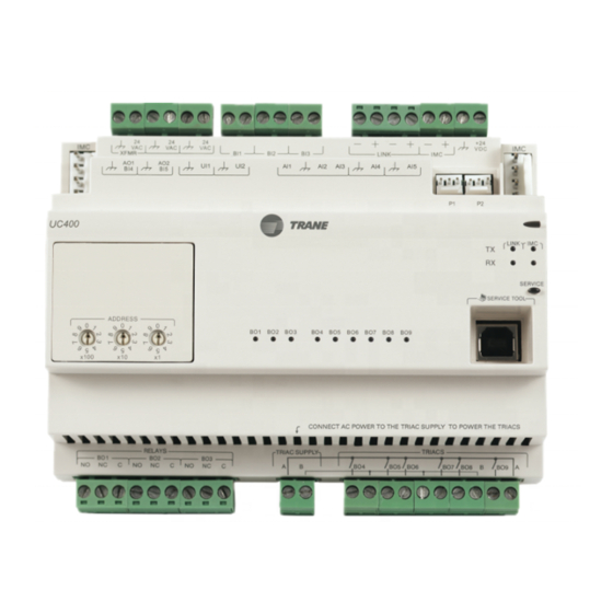
Tracer™ UC400 Programmable BACnet Controller
For Variable-Air-Volume (VAV) Units
Only qualified personnel should install and service the equipment. The installation, starting up, and servicing of heating, ventilating, and air-
conditioning equipment can be hazardous and requires specific knowledge and training. Improperly installed, adjusted or altered equipment
by an unqualified person could result in death or serious injury. When working on the equipment, observe all precautions in the literature and
on the tags, stickers, and labels that are attached to the equipment.
May 2013
SAFETY WARNING
VAV-SVX07B-EN
Advertisement
Table of Contents
Troubleshooting

Subscribe to Our Youtube Channel
Related Manuals for Trane Tracer


Summary of Contents for Trane Tracer
- Page 1 Installation, Operation, and Programming Tracer™ UC400 Programmable BACnet Controller For Variable-Air-Volume (VAV) Units SAFETY WARNING Only qualified personnel should install and service the equipment. The installation, starting up, and servicing of heating, ventilating, and air- conditioning equipment can be hazardous and requires specific knowledge and training. Improperly installed, adjusted or altered equipment ...
- Page 2 Copyright © 2013 Trane. All rights reserved. This document and the information in it are the property of Trane and may not be used or reproduced in whole or in part, without the written permission of Trane. Trane reserves the right to revise this publication at any time and to make changes to its content without obligation to notify any person of such revision or change.
-
Page 3: Table Of Contents
......28 Installing Tracer TU Service Tool ....... . 28 Connection Instructions . - Page 4 Analog Tab ..........31 Binary Tab .
- Page 5 VAV Modulating Hot Water Failure ......74 Trane/Honeywell Proportional Valve Check Out ....75 Appendix: Typical Trane Factory Wiring Diagrams .
-
Page 6: Overview
(DDC). This controller can be installed as a factory or field device. When this controller is factory installed on Trane™ variable-air-volume (VAV) terminal units, the factory downloads the unit with the appropriate VAV programs and configuration settings for the unit. -
Page 7: Specifications And Dimensions
• Communications BACnet MS/TP , supports BACnet protocol ASHRAE 135-2004 and meets BACnet Testing Laboratory (BTL) as an Application Specific Controller (ASC) profile device UL864/UUKL listed when installed and programmed in accordance with the Trane Applications Guide, BAS-APG019-EN. 2.37 in 5.65 in. -
Page 8: Shipping And Storage
Flexibility: to select priority for either local or remote heat has. The UC400 controller has spare I/Os that are not used by the VAV applications. These spare I/Os can be programmed using the Tracer Spare Inputs/Outputs: Graphical Programming editor (by means of the Tracer TU service tool) to measure and/or control ancillary devices such exhaust fans, second air valve for dual duct VAV, or sensing relative humidity. -
Page 9: Controller Comparisons
Comparison of the UC400 to VV550/551 Tracer UC400 VAV Tracer VV550/VV551 VAV 4.2 Supports BACnet. Supports LonTalk. Supports Trane proprietary Comm4 or Comm3. No local CO sensor input. Uses only a communicated Local CO sensor input is available. Local CO sensor input is available. -
Page 10: Device Connections
Overview Device Connections The following table provides information about the types of device connections. Connection Quantity Types Range Notes Temperature 10 kthermistor AI1 to AI4 can be configured for timed override Analog input capability. Setpoint 189 to 889 (AI1 to AI5) Resistive 100 ... -
Page 11: Device Inputs/Outputs
24 Vac, Class II power In addition to the points used for the VAV application, the spare inputs and outputs on the UC400 controller may be used for ancillary control and programmed using Tracer TU Tracer Graphical Programming 2 (TGP2). -
Page 12: Pressure Inputs
– Voltage output is 0 to 10 Vdc, 500 minimum impedance. – Current output is 4-20 mA, 500 max. impedance. – Also can output 100 Hz PWM signal for control of a Trane fan-powered ECM fan setpoint signal to the EC motor. -
Page 13: Wiring Installation
Wiring Installation This section provides wiring guideline information about the following: • “UC400 Controller Pre-power Check-out” • “UC400 Controller Power Wiring, ” p. 14 • “BACnet MS/TP Communication Link, ” p. 16 • “Application Wiring, ” p. 22 UC400 Controller Pre-power Check-out Carefully follow the check-out procedures below and read all warnings and notices. -
Page 14: Uc400 Controller Power Wiring
Size the transformer to provide adequate power to the UC400 controller (24 VA maximum) and outputs (maximum 12 VA for each binary output). Important: A dedicated 24 Vac, Class 2 transformer is recommended to power the Tracer UC400 controller. When powering multiple controllers from one transformer, polarity must be maintained. - Page 15 • 0.34 VA including actuator draw) • Total • 9.2 VA (Plus air damper draw) With a Trane F Series Box: 13.2 VA Total (a) See device connected to DC supply for current draw. • Replace the control box cover after field wiring to prevent any electromagnetic interference.
-
Page 16: Bacnet Ms/Tp Communication Link
“Setting Up the UC400 Controller on a BACnet Link, ” p. 18 • “Setting the Address, ” p. 18 • “BACnet Networks Without a Tracer SC System Controller, ” p. 19 • “BACnet Networks With a Tracer SC System Controller, ” p. 19 •... -
Page 17: Wiring Best Practices
UC400 controller IMC terminals to the zone sensor communication module. • Zone Sensor communication wiring length limits of 300 ft. (100 m). Note: For more details, refer to the Unit Controller Wiring for the Tracer SC™ System Controller Wiring Guide (BAS-SVN03). VAV-SVX07B-EN... -
Page 18: Setting Up The Uc400 Controller On A Bacnet Link
Valid MAC addresses are 001 to 127 for BACnet. Important: Each device on the link must have a unique MAC Address/Device ID. A duplicate address or a 000 address setting will interrupt communications and cause the Tracer SC device installation process to fail. -
Page 19: Bacnet Networks Without A Tracer Sc System Controller
BACnet Device ID are 042, OR • It can be soft set using Tracer TU service tool. If the BACnet Device ID is set using Tracer TU service tool, the rotary address dials only affect the MAC Address, they do not affect the BACnet Device ID. -
Page 20: Wiring Requirements
Wiring Installation Wiring Requirements To ensure proper operation of the UC400 controller, install the power supply circuit in accordance with the following guidelines: • The controller must receive AC power from a dedicated power circuit. Important: Failure to comply may cause the controller to malfunction. •... -
Page 21: Power On Check
Wiring Installation Power On Check 1. Verify that the 24 Vac connector and the chassis ground are properly wired. 2. Remove the lockout/tagout from the line voltage power to the electrical cabinet. 3. Energize the transformer to apply power to the UC400 controller. 4. -
Page 22: Application Wiring
Wiring Installation Application Wiring This section provides information about pre-configured wiring for the following applications: • “Zone Sensor Wiring” • “Duct Temperature Sensor Wiring, ” p. 24 • “Binary Wiring, ” p. 24 Note: For more details about mounting, wiring, and configuring wireless zone sensors, refer to the section, “Additional Resources, ”... - Page 23 If local codes require enclosed conductors, install the zone sensor wires in the conduit. • Refer to “Appendix: Typical Trane Factory Wiring Diagrams, ” p. Important: Control wires and power conductors can never be near each other (except at 90 degrees). Do not run power wired through same conduit as signal wires.
-
Page 24: Duct Temperature Sensor Wiring
Each UC400 controller provides three (3) binary inputs (BI1–BI3) with one being configured for occupancy with the standard VAV code. The binary inputs can be configured with the Tracer TU service tool for occupancy or other use. The input associates 0 Vac with open contacts and 24 Vac with closed contacts. - Page 25 Binary outputs that are required for unit operation are factory wired and commissioned. The UC400 controller does have extra binary outputs available for other use with most configurations. To program the extra outputs on the UC400 controller, refer to the Tracer UC400 Programmable Controller Installation, Operation, and Maintenance Manual (BAS-SVX20) and the Application Guide for UC400 VAV Operation (BAS-APG010).
-
Page 26: Controller Operation
Service button LED • Three (3) binary output relay and six (6) TRIAC status LEDs • For details about wiring communication links, refer to the Tracer SC Unit Controller Wiring Guide (BAS-SVN03). Marquee LED Table 5. LED Activities and Troubleshooting Tips... - Page 27 LED not lit: the link. RX blinks yellow. Determine if, for example, a Tracer SC or Link and IMC BACnet device is trying to talk to the • ON solid yellow; indicates there is controller or if it is capable of talking to reverse polarity.
-
Page 28: Tracer™ Uc400 Controller Operations
“Equipment Settings Button, ” p. 40 Connecting with the Tracer TU Service Tool The Tracer TU service tool is a service tool that allows parameters to be viewed or adjusted in the Tracer UC400 controller. It is a software application for monitoring, configuring, balancing, and testing Trane unit controllers, such as the Tracer UC400 controller. -
Page 29: Status Button
Note: Example based on a UC400 configured for Space Temperature Control. The Tracer TU service tool will launch and display the status of the Tracer UC400 controller. • The left-hand side contains the device tree listing all of the devices on the link. (To access another controller on the link, click on the device on the tree). - Page 30 Occupied Bypass mode. • Heat /Cool Status: The heat/cool status displays the heating and cooling mode of the Tracer UC400 controller. This is where the controller displays the heating or cooling mode of the controller. The controller can receive communicated requests for heating or cooling operation.
-
Page 31: Analog Tab
View Details dialog boxes can be accessed by clicking on the details buttons, located at the end of each line item. Note: For field use of spare analog points, refer to the Tracer UC400 Programmable Controller Installation, Operation, and Maintenance Manual (BAS-SVX20). -
Page 32: Binary Tab
View Details dialog boxes may be accessed by clicking on the details buttons, located at the end of each line item. Note: For field use of spare analog points, refer to the Tracer UC400 Programmable Controller Installation, Operation, and Maintenance Manual (BAS-SVX20). -
Page 33: Controller Status Tab
BAS Communication: Displays the status of communications with the Tracer SC. Program The Tracer UC400 controller has up to three (3) TGP2 programs downloaded and defined in the factory as part of the factory commissioning process. The three programs are a base program for damper control, fan, and reheat control. -
Page 34: Alarms Tab
Model: Displays the model number of the controller. • BAS Communication: No parent configured indicates standalone operation, or non-Trane system controller. Comm Up or Comm Down indicates communication status with Tracer SC. Alarms Grid The grid columns are as follows. -
Page 35: View Graphs Tab
Tracer™ UC400 Controller Operations View Graphs Tab The View Graphs tab contains controls used to set up and generate graphs (line charts) presenting a subgroup of logged data points. Use predefined templates or define custom graphs. The user can save the graph definition as a new template. -
Page 36: Data Log Setup Tab
Cancel: Returns the screen to its condition at the last save. Capturing Data & Troubleshooting Occasionally, it may be necessary to troubleshoot a difficult equipment problem. Use the Tracer TU Data Logging Utility to capture data for review. A maximum of 25,000 samples can be stored on the UC400. -
Page 37: Controller Settings Utility
View analog, binary, and multistate points and I/O references • Configure new points and edit the configuration of existing points • Set the Tracer UC400 controller date and time, including format and time zone • Set the Tracer UC400 controller units (SI or IP) •... -
Page 38: Controller Settings Tab
Tracer™ UC400 Controller Operations Edit an Existing Point Use the Analog, Binary, and Multistate tab screens on the Controller Settings button to edit point definitions. 1. Click the Analog, Binary, or Multistate tab. 2. Select the check box on the left side the row of the point to edit. - Page 39 Set Up the Use Software Device ID Specify a software device ID using the Tracer TU service tool tab Controller Settings screen on the Controller Settings Utility tab, if the BACnet protocol is being used at the job location. A software device ID is useful when integrating Trane equipment into a non-Trane environment.
-
Page 40: Equipment Settings Button
Tracer™ UC400 Controller Operations Equipment Settings Button Use the Equipment Settings button to set setpoints and other settings in the Tracer UC400 controller, as well as configure the controller parameters. In addition, the user can change a number of equipment setpoints and setup parameters from the Equipment Utility screens. Scroll down through the expanding boxes to locate the desired setpoints to change. -
Page 41: Setup Parameters Tab
Typically, it is not necessary to change this value. For Trane units, the nominal airflow and unit flow gain are based on unit size and are not adjustable. The default unit flow gain for generic VAV boxes is 1.0. - Page 42 Ventilation Setup • Ventilation Setpoint Local: The Tracer SC BAS uses the ventilation setpoint from all the VAV boxes to calculate how much outdoor air (OA) the system needs. During the occupied mode, this setpoint is the active setpoint for ventilation.
-
Page 43: Commissioning Tab
• Calibrate Air Valve: Use the Tracer TU service tool Air Balancing tool and the Trane Air Balancing Calculation spreadsheet to perform a basic two-point air balance for the Tracer UC400 controller - VAV application. - Page 44 Note: The entered value is retained for the next session when closing this dialog box. However, the value is deleted if exiting Tracer TU.The Measured Minimum Airflow value is treated the same way.
-
Page 45: Overrides
Profile: This allows for selection between three operational programs. The three programs are Space Temperature, Ventilation Flow, and Flow Tracking. Equipment Options • Box Size: Used to select a Trane F-style box size or Generic Box. • Air Damper Opens: Chose between Clockwise and Counter-Clockwise damper rotation to open the damper. -
Page 46: Calibration, Operation Modes, And Control
Calibration, Operation Modes, and Control This section provides information about the following: • “Calibration” • “Occupancy Modes, ” p. 46 • “Space Temperature Control (STC) for Single Duct and Fan-powered Units, ” p. 48 • “Ventilation Flow Control (VFC), ” p. 55 •... -
Page 47: Unoccupied Mode
Calibration, Operation Modes, and Control Unoccupied Mode Unoccupied mode, known as night setback, is the normal operating mode for unoccupied spaces or nighttime operation. Unoccupied setpoints enable or disable occupied space temperature control. When the controller is in the unoccupied mode, and configured for space temperature control, the controller attempts to keep the space temperature between the active unoccupied heating setpoint and the active unoccupied cooling setpoint. -
Page 48: Space Temperature Control (Stc) For Single Duct And Fan-Powered Units
Calibration, Operation Modes, and Control Space Temperature Control (STC) for Single Duct and Fan-powered Units Single Duct Units Space Temperature Control Mode Space temperature control is one of three supported control algorithms (the other two supported control algorithms are “Ventilation Flow Control (VFC), ” p. 55 “Flow Tracking (FTC), ”... - Page 49 Calibration, Operation Modes, and Control All units have a modulating air valve that is used to control how much air is flowing through the diffusers and into the space. By modulating the volume of airflow, the unit heating capacity is modulated.
- Page 50 Airflow Setpoint Minimum Local Heat. Refer to the equipment catalog for Trane F-Style VAV boxes for minimum airflow settings based on box inlet size and heating element kW.
- Page 51 Calibration, Operation Modes, and Control Table 6. Local Heat Only With No Fan Present Configuration Method of Control Local Remote Stage 1 Stage2 Stage 3 • Local PI capacity loop PWM electric • Each stage represents an equal percentage of total capacity PWM Output (one stage = 100%; two Not applicable (1 to 3 stages) stages = 50% each;...
- Page 52 Calibration, Operation Modes, and Control Table 7. Local Heat Only With Parallel Fan Present (continued) Configuration Method of Control Local Remote Fan Stage 1 Stage 2 Stage 3 Local thermostatic: Local thermostatic: Local thermostatic: • On: Zt < HSP - 2°F (1.11°C) •...
-
Page 53: Fan-Powered Units
Calibration, Operation Modes, and Control On/Off Electric Reheat The Airflow Setpoint Minimum Local Heat is enforced during reheat. • Stage 1; energizes when the space temperature falls below the active heating setpoint and minimum airflow requirements are met. When the zone temperature rises above the active heating setpoint by 0.5°F (0.28°C), stage 1 is de-energized. - Page 54 Calibration, Operation Modes, and Control ECM Fan This controller supports an electronically commutated motor (ECM). The controller turns the ECM fan ON and OFF . It does not change the ECM fan airflow dynamically. The fan operates at a single speed to match the fan flow setpoint.
-
Page 55: Ventilation Flow Control (Vfc)
Calibration, Operation Modes, and Control • When the supply airflow is greater than the active minimum flow setpoint, plus 5% of the configured nominal airflow. In pressure dependent mode, the air valve position is substituted for the supply airflow. Parallel Fan Operation During Calibration During calibration, the parallel fan is in the same state (ON or OFF) prior to the start of calibration. - Page 56 Calibration, Operation Modes, and Control Air Valve Control Ventilation flow control uses the air valve as a constant volume device. The unit is given a constant flow setpoint for air valve control (configured ventilation setpoint). The air valve only repositions itself in response to changes in inlet static pressure.
- Page 57 Calibration, Operation Modes, and Control Freeze Protection (Hot Water Only) Units with hot water coils installed are susceptible to freezing. It is important to prevent the water coils from freezing. Freeze protection occurs only when the controller is in the OFF state or during the unoccupied period when the supply air valve is closed and the reheat is disabled.
-
Page 58: Flow Tracking (Ftc)
Air Flow Setpoint BAS. Note: This must be set up on the Tracer SC using either a global reference or TGP2 program. for more details, refer to the Air Systems for Tracer SC Application Guide (BAS-APG007). -
Page 59: Troubleshooting
Troubleshooting This section provides information about the following: • “Diagnostics” • “Troubleshooting Procedures, ” p. 60 WARNING Live Electrical Components! During installation, testing, servicing, and troubleshooting of this product, it may be necessary to work with live electrical components. Have a qualified licensed electrician or other individual who has been properly trained in handling live electrical components perform these tasks. -
Page 60: Troubleshooting Procedures
If it does operate properly check, inputs/outputs for a short. – If controller still fails, replace controller. Note: For Instructions on how to use Tracer TU, refer to the Tracer TU Online Help and to the Tracer TU Service Tool Getting Started Guide (TTU-SVN02). -
Page 61: Uc400 Controller Communication Loss
– Verify that there are no duplicated addresses on the communication link. • Check for alarms or diagnostics with Tracer TU service tool, and check that the communication link avoids interference. Communication link should not be routed near or with any voltage source. -
Page 62: Wired Zone Sensor Failure
Check application version and build or download the latest application version using the Tracer TU service tool. Note: For instructions on how to use Tracer TU, refer to the Tracer TU online Help and the Tracer TU Service Tool Getting Started Guide (TTU-SVN02). - Page 63 Troubleshooting • Verify that the zone sensors are not shorted out. Check the resistance across the wires. Disconnect wires from the UC400 controller and zone sensor, ensuring that the ends are not touching each other, and then measure resistance. It should be infinite or no conductivity. If lower resistance is shown, then the wires are shorted together and need to be replaced.
-
Page 64: Wired Zone Sensor Setpoint Failure
Troubleshooting Wired Zone Sensor Setpoint Failure WARNING Hazardous Service Procedures! The maintenance and troubleshooting procedures recommended in this section of the manual could result in exposure to electrical, mechanical or other potential safety hazards. Always refer to the safety warnings provided throughout this manual concerning these procedures. When possible, disconnect all electrical power including remote disconnect and discharge all energy storing devices such as capacitors before servicing. -
Page 65: Airflow Sensor Failure
• Recalibrate the VAV unit by cycling power to unit. This can also be accomplished with Tracer TU service tool or Tracer SC. Important: Cycling power to the VAV board: The default will automatically cause the unit to calibrate, but this depends on binary value, auto-calibrate, enable/disable point. - Page 66 • Poor inlet configuration. – Trane recommends 1½-duct diameters of straight duct before the inlet of the box (a 12-inch box should have 18 inches of straight run duct before the inlet). •...
-
Page 67: Supply/Discharge Air Temperature Sensor Failure
Troubleshooting Supply/Discharge Air Temperature Sensor Failure WARNING Hazardous Service Procedures! The maintenance and troubleshooting procedures recommended in this section of the manual could result in exposure to electrical, mechanical or other potential safety hazards. Always refer to the safety warnings provided throughout this manual concerning these procedures. When possible, disconnect all electrical power including remote disconnect and discharge all energy storing devices such as capacitors before servicing. -
Page 68: Co2 Sensor Failure
Note: If the CO sensor is not set up for 4 –20 mA, the CO input can be put out of service with Tracer TU, changed to the 0–20 mA or 0–10 Vdc in the configuration screen, and then put back in service. -
Page 69: Vav Damper Failure
In the event that the air valve does not modulate, check the following: • Tracer SC or Tracer TU service tool has enabled an override function in the UC400. Verify no overrides are present by clicking on the override icon of multistate value 2, Air Flow Override, on the TU Multistate Status page. -
Page 70: Vav Series Fan Failure
Tracer SC has the fan output disabled. Check overrides to ensure they are not inhibiting fan operation. • A flow override exists locking out the fan output. Ensure that either Tracer SC or the Tracer TU service tool has released fan disable override. •... -
Page 71: Vav Parallel Fan Failure
TU binary status page. • A flow override exists locking out the fan output. Ensure that either Tracer SC or the Tracer TU has released fan disable override. Flow overrides can be checked on the TU multistate status page. -
Page 72: Psc (Permanent Split Capacitor) Variable Speed Motor Check
If the PSC Variable speed motor control does not change the motor speed, check the following: • Wires connected improperly. Refer to the section, “Appendix: Typical Trane Factory Wiring Diagrams, ” p. • Check voltage selection switch on side of variable speed motor control. It should be set for motor voltage. -
Page 73: Vav Electric Heat Stage Failure
Verify the output configuration in the UC400 controller setup screen. Unit needs to be configured as 3-stage electric heat. • Tracer SC has the electric heat output disabled. Check group, global, and/or Tracer overrides to make sure they are not inhibiting heat operation. •... -
Page 74: Vav Modulating Hot Water Failure
Verify the valve control type selection on the TU Equipment Configuration screen. Unit needs to be configured as modulating hot water. • Tracer SC has the heat output disabled. Check overrides to ensure they are not inhibiting heat operation. •... -
Page 75: Trane/Honeywell Proportional Valve Check Out
• Verify the output configuration in the UC400 controller setup screen. Unit needs to be configured as proportional hot water. • Tracer SC has the heat output disabled. Check overrides to ensure they are not inhibiting heat operation. VAV-SVX07B-EN... - Page 76 Troubleshooting • Heat relays have failed. – The UC400 controller will call for the valve to be OPEN, (viewed in the Status screen). If not, check the TRIAC output, wiring connections, and relay output. – If the UC400 controller is calling for the heat output to be ON (viewed in the Status screen), then the LED is OFF for the correct Binary Output 7 to open the valve (note, polarity is reversed on this point).
-
Page 77: Appendix: Typical Trane Factory Wiring Diagrams
Appendix: Typical Trane Factory Wiring Diagrams Figure 5. UC400 Controller Wiring for Single Duct Unit VAV-SVX07B-EN... - Page 78 Appendix: Typical Trane Factory Wiring Diagrams Figure 6. UC400 Controller Wiring for Fan Powered Unit VAV-SVX07B-EN...
-
Page 79: Additional Resources
• BACnet MS-TP Wiring and Link Performance Best Practices and Troubleshooting Guide (BAS-SVX51) • Engineered Smoke Control System for Tracer™ SC System Controller Application Guide (BAS- APG019) • Tracer™ UC400 Controller BACnet Protocol Implementation Conformance Statement (PICS) [BAS-PRG007] •... -
Page 80: Declaration Of Ce Conformity
Electromagnetic Immunity 02/19/2009 Mark of Compliance: European Contact Societe Trane (Epinal, France) 1, rue des Ameriques, B.P. 6 F-88191 Golbey Cedex, France Phone: (33) 329.31.73.00 Fax: (33) 329.81.24.98 This document validates CE conformity of the Tracer UC400 Unit Controller VAV-SVX07B-EN... -
Page 81: Index
26 Temperature Sensor Wiring Guidelines 16 service 27 Failure 67 Wiring Requirements 20 Trane/Honeywell Proportional With a Tracer SC System Valve Check Out 75 Occupancy Modes 46 Controller 19 UC400 Controller Occupied Bypass Mode 47 Without a Tracer SC System... - Page 82 Index Protection 57 Unoccupied Ventilation Flow Control 57 Wiring Diagrams 77 Fan Powered Unit 78 Single Duct Unit 77 Wiring Installation Guidelines 14 UC400 Controller Power Wiring 14 UC400 Controller Pre-power Check-out 13 VAV-SVX07B-EN...
- Page 84 HVAC systems, comprehensive building services, and parts. For more information, visit www.Trane.com. Trane has a policy of continuous product and product data improvement and reserves the right to change design and specifications without notice. © 2013 Trane. All rights reserved.
Need help?
Do you have a question about the Tracer and is the answer not in the manual?
Questions and answers