
Subscribe to Our Youtube Channel
Related Manuals for Trane Tracer ZN524


Summary of Contents for Trane Tracer ZN524
- Page 1 Installation Owner Diagnostics Tracer ® ZN524 for water-source heat pumps Order No: CNT-SVX11A-EN Date: August 2003 CNT-SVX11A-EN...
- Page 2 Notice Notice Warnings and Cautions appear at appropriate sections throughout this manual. Read these carefully. WARNING - Indicates a potentially hazordous situation which, if not avoided, could result in death or serious injury - Indicates a potentially hazordous situation CAUTION which, if not avoided, could result in minor or moderate injury.
-
Page 3: Table Of Contents
Contents Start-up Procedures General Information Control Circuit Board Features Control Features Communication Configurations Installation and Wiring Typical Wiring Diagram— Waterside Ecomomizer Typical Wiring Diagram— Hot Gas Reheat Configuration Location Identifier Unit Operation Troubleshooting Replacing Circuit Boards Appendix Appendix—Binary Configuration Appendix—Unit Operation Appendix—Data Lists Appendix—Location Identifier CNT-SVX11A-EN... -
Page 4: Start-Up Procedures
7. Check for YELLOW Comm LED opera- tion to help ensure communication has 8. Normal operation begins after 290 been made to the Tracer ZN524 unit (potentially) seconds have passed. controller when applicable. Note: Manual output test can be 8. -
Page 5: General Information
General Information Tracer® ZN524 Overview The Trane Tracer® ZN524 controller is a factory-installed and commissioned, direct-digital controller (DDC) offering for single or dual compressor water- source heat pump systems. (See Figure 1: “Tracer ZN524 Control Board”) Trane offers a complete solution to... -
Page 6: Control Circuit Board Features
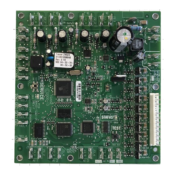
Controller Circuit Board and Features Figure 2: Tracer ZN524 unit controller circuit board Controller features: D. Auto Test Button E. Zone Sensor Connections A. Power Connections F . Service Button/LED B. Generic Connections (BOP) G. Communications Connections C. Status LED H. -
Page 7: Control Features
• Quick terminal connectors, and • Easy to read screen printing. (See Figure 2: Page 6). Service The Trane Tracer ZN524 unit controller is serviced using Rover®, the software service tool. Rover is designed to sup- port the Tracer ZN524 unit controller on a single or dual compressor water- source heat pump. -
Page 8: Communication Configurations
Tracer Summit. Figure 4: Communications link wire The Tracer ZN524 is linked directly to Peer-to-peer communications allows the Tracer Summit via a twisted pair features such as master/slave opera- communication wire. - Page 9 Rover service Service tool routines. tool, and other unit controllers on the Trane also offers a service tool to work communications link. Each Tracer These sensors are required for proper in conjunction with the Tracer Summit ZN524 requires a unique address for...
-
Page 10: Installation And Wiring
• -40° to 185°F (-40° to 85°C) • 5% to 95% relative humidity, non- condensing Agency Listings • UL and CUL 916 Energy Management System • Agency Compliance IEC 1000-4-2 (ESD), IEC 1000-4-4(EFT), IEC 1000-4-5 (Surge) Figure 7: Tracer ZN524 circuit board schematic CNT-SVX11A-EN... - Page 11 Fan status or not used Normally open J2 - 8 Input Normally closed 1. Trane Rover service tool uses the unit type to help determine and download the proper default binary input configuration. Table 2: Binary output summary Binary Function Valid range...
- Page 12 0 - 2000 ppm 1. Trane Rover service tool uses the unit type to help determine and download the proper default analog input configuration. 2. Analog input 3 (AI 3) configured as generic temperature input does not affect unit operation. When configured, the Tracer ZN524 unit con- troller communicates the generic temperature value to Rover or Tracer Summit and displays it as generic temperature.
- Page 13 Hazardous Voltage! components of the control board. Disconnect all electric power, including The Tracer ZN524 circuit board is locat- remote disconnects before servicing. ed in the control box, which is mounted The mounting plate on both the hori-...
- Page 14 • All sensor and input circuits are at or near ground potential. Do not connect any sensor or input circuit to an external ground connection. • A close-coupled ground connection is ZN524 Figure 10: Power connections to the Tracer ZN524 unit controller CNT-SVX11A-EN...
- Page 15 Installation & Wiring Installing the Wall-Mounted • In air flows from adjacent zones or other units. Zone Sensor (Optional) The communications link is not con- nected in the factory. Communications Zone sensor location is an important could be wired to the wall-mounted element of effective room control and sensor if desired.
- Page 16 Table 6: Zone Sensor Options Part number: X13510628010 Description: • Space temperature (0.2 C resolution) • Internal setpoint • Communication jack • Vertical case with Trane logo Part number: X13510606010 Description: • Space temperature (0.2 C resolution) • External setpoint • Communication jack •...
- Page 17 X13510606020 Description: • Space temperature (0.2 C resolution) • ON and CANCEL buttons • External setpoint • Communication jack • Vertical case with Trane logo Part number: X13510635010 Description: • Space temperature (0.2 C resolution) • ON and CANCEL buttons •...
-
Page 18: Typical Wiring Diagram
Typical wiring diagram Figure 12: Wiring diagram with Waterside Economizer option CNT-SVX11A-EN... -
Page 19: Typical Wiring Diagram
Typical wiring diagram Figure 13: Wiring diagram with Hot Gas Reheat option CNT-SVX11A-EN... -
Page 20: Hot Gas Reheat
Configuration Trane configures the Tracer® ZN524 water-side economizer, hot gas reheat, Unit Controller at the factory per the electric heat or boilerless units. Table 7 selected unit configuration. The con- defines the configuration options sup- troller is applied to water-source heat ported by the ZN524 controls. - Page 21 Configuration Table 8: Fan configuration ranges Fan configuration Default Valid range Fan operation in heating Continuous Continuous Cycling with capacity Fan operation in cooling Continuous Continuous (during occupied) Cycling with capacity (unoccupied) Number of fan speeds Configurable fan speed heating High Off, high, auto Configurable fan speed cooling...
- Page 22 Configuration Occupied Bypass Timer Table 11: Bypass timer range Default Valid Range Occupancy bypass timer 120 minutes 30 to 240 minutes ( 1-minute resolution) 1. The occupied bypass timer is used for timed override applications. Power-up Control Wait Table 12: Control wait timer Default Valid Range Power up control wait (2 minutes)
-
Page 23: Location Identifier
• NID (neuron identification number)— The NID is similar to the serial number of the unit but is specific to the identifi- cation of the Tracer ZN524 unit con- Figure 14: Water-source heat pump troller circuit board (B) unit identification tag. -
Page 24: Unit Operation
When 24 VAC is initially applied to the bypass or by using the controller, the following sequence of TIMED OVERRIDE mode (i.e., ON) button on the Trane zone sen- events occurs: NOCCUPIED When the controller is in the sor. mode, the unit attempts to •... - Page 25 Unit Operation Figure 15: Heat/Cool Changeover logic All other numers will be interpreted as The Tracer™ ZN524 Unit Controller Auto. changes from heating to cooling and cooling to heating when the integration As the controller automatically deter- term exceeds (900 •...
- Page 26 Fan Operation Entering Water Temperature Sampling Function During the mode, the Tracer The Tracer ZN524 controller also allows COOLING ZN524 controller attempts to maintain the fan speed to be configured as auto. The Tracer ZN524 controller will sample the space temperature at the active...
- Page 27 Unit Operation EWT sampling will be invoked when The following chart provides a quick trips ( in alarm situations) the following the following conditions have been reference to unit configurations in actions will occur: met: which EWT is enabled: • EWT is not communicated via a BAS Cooling Mode Control Action and:...
- Page 28 Electric Heat Operation Compressor (DX) Cooling • Upon opening, the valves remain open for a 10 minute minimum to The Tracer ZN524 supports 1-stage elec- The ZN524 controller supports two reduce excessive valve cycling. tric heat in one of three ways: stages of DX cooling.
- Page 29 No pulse width modulation is compared against the relative humidity used during dehumidification. The Tracer ZN524 controller keeps the enable/disable setpoints. Relative 2-position outdoor air damper closed humidity level can be communicated to...
- Page 30 The fan status is reported as off when the fan output is directed 2. The Tracer ZN524 controller has a binary input available for a fan status device (current sensing relay) which can provide feedback of fan operation.
- Page 31 “Appendix—Data ed pair of communication wire with or The Tracer ZN524 controller includes a Lists” on page 47. without the presence of a front end network variable for master/slave oper- building management system.
-
Page 32: Troubleshooting
Troubleshooting Important! When viewing the Tracer seconds, the Tracer ZN524 Unit Yellow Comm LED ZN524 through the Rover service Controller will uninstall itself from The yellow Comm LED blinks at the tool, it is important that the the ICS communication network rate the controller receives communica- version be up-to-date. - Page 33 Troubleshooting If a two-blink pattern remains after an Test Procedure Note: To help ensure accurate attempt to clear diagnostics, the diag- testing do not press the test button more than once per second. nostic condition is still present and may The procedure for testing is: affect the manual output test.
- Page 34 Diagnostics Local Setpoint Failure Sensor Failure If the hardwired setpoint input to the If the Tracer ZN524 has validated a CO Tracer ZN524 controller is present and input and then the input becomes Fan Failure then becomes invalid, a local setpoint A “Low Air Flow—Fan Failure”...
- Page 35 Troubleshooting Table 19: Tracer ZN524 Unit Controller diagnostics Diagnostic Unit Response Latching/ Reset non-latching Fan—off Auto reset once within 24 hrs. Valves—closed If safety generates a diagnostic High/Low Pressure Compressor - off Latching more than once a communicated Cutout or manual reset will be necessary Fan—off...
- Page 36 Troubleshooting Table 19: Tracer ZN524 Unit Controller diagnostics - continued Diagnostic Unit Response Latching/ Reset non-latching Fan—enabled Valves—enabled Humidity Input Failure Compressor—enabled Non-latching Communicated or manual reset Reheat—disabled CO2 Sensor Fan—enabled Failure Valves—enabled Non-latching Communicated or manual reset Compressor—enabled Generic...
- Page 37 24 hours after an Rover service tool can reset diagnostics Diagnostics automatic diagnostic reset, you must in the Tracer ZN524 unit controller. For manually reset the diagnostic. See more complete information, refer to the The controller senses and records each...
- Page 38 No power to the controller If the controller does not have power, the unit fan does not operate. For the Tracer ZN524 Unit Controller to operate normally, it must have an input voltage of 24 VAC. When the green LED is off continuously, the controller does not have sufficient power or has failed.
- Page 39 For more information see, Manual Output Test, on page 32 for more information.) Fan mode off When a local fan mode switch (provided on the Trane zone sensor) determines the fan operation, the off position controls the unit off and valves to close.
- Page 40 For more information see, Manual Output Test, on page 32 for more information.) Fan mode off When a local fan mode switch (provided on the Trane zone sensor) determines the fan operation, the off position controls the unit off and damper to close.
- Page 41 Troubleshooting Table 23: Outdoor air damper stays closed - continued Probable cause Possible Explanation Requested mode off You can communicate a desired operating mode (such as off, heat, and cool) to the controller. When off is communicated to the controller, the unit controls the fan off. There is no heating or cooling (valves are closed).
-
Page 42: Replacing Circuit Boards
Replacing Circuit Boards Tracer ZN524 Unit Controller Connect the remaining input and output wiring to the controller and Replacement comm wire. WARNING 8. Reapply power. Hazardous Voltage! Disconnect all electric power, including 9. Complete sequence 7 and 8 above remote disconnects before servicing. -
Page 43: Appendix
Appendix Hardwired Setpoint Adjustment Table 26: Hardwired setpoint adjustment Resistance (V V ) Setpoint (°F) 889.4 733.6 577.9 422.1 344.2 266.4 188.5 110.6 Fan Switch Resistance Values Table 27: Resistance Values Resistance (V V ) Switch Position 16,300 High 10,700 2,320 Auto 4,870... -
Page 44: Appendix-Binary Configuration
Appendix - Binary Configuration Binary Configuration Table 29: Binary configuration details Binary input Function Configuration Description or output BI 1 Low temp detection Normally closed Closed: BIP 1 is Normal (no diagnostic) Open: BIP 1 is Active (diagnostic) BI 2 Condensate overflow Normally closed Closed: BIP 2 is Normal (no diagnostic) -
Page 45: Appendix-Unit Operation
Appendix - Unit Operation Unit Operation Based On The Effective H Output Table 30: Unit operation based on H ouput Application Heat/cool mode input Effective heat/ cool Unit Operation mode input mode output (nviHeatCool) (nviApplicMode) (nvoHeatCool) Auto Determined by controller Fan—Enabled Heating—Enabled Cooling—Enabled... - Page 46 Any state Fan only Fan—Enabled Heating—Disabled Cooling—Disabled Damper—Enabled Note: Night purge, Emergency heat, and Nul modes are not supported by the Tracer ZN524 Unit Controller. If one of these modes is received by the controller, it is interpreted as Auto. CNT-SVX11A-EN...
-
Page 47: Appendix-Data Lists
Appendix - Data Lists Data Lists Table 31 provides an input/output list- ing for the Tracer ZN524 unit controller. The content of the lists conforms to both the LonMark Space Comfort Controller Functional Profile and the LonMark node object Table 31: Input/Output listing... -
Page 48: Appendix-Location Identifier
Location Identifier CNT-SVX11A-EN... - Page 49 Location Identifier CNT-SVX11A-EN...
- Page 50 Location Identifier CNT-SVX11A-EN...
- Page 51 Location Identifier CNT-SVX11A-EN...
- Page 52 A business of American Standard Companies www.trane.com Stocking Location Inland Trane has a policy of continuous product and product data improvement and For more information, contact reserves the right to change design and specifications without notice. your local district office or...
Need help?
Do you have a question about the Tracer ZN524 and is the answer not in the manual?
Questions and answers