Trane Tracer UC400 Installation Manual
Residential touch screen programmable zone sensor
Hide thumbs
Also See for Tracer UC400:
- Installation, operation and maintenance manual (68 pages) ,
- Installation instructions (2 pages) ,
- Uc (84 pages)
Table of Contents
Advertisement
Quick Links
Installation Guide
Trane® Residential Touch Screen
Programmable Zone Sensor
for Tracer® UC400 Controls
Model Number:
X13790992001
Only qualified personnel should install and service the equipment. The installation, starting up, and servicing of
heating, ventilating, and air-conditioning equipment can be hazardous and requires specific knowledge and training.
Improperly installed, adjusted or altered equipment by an unqualified person could result in death or serious injury.
When working on the equipment, observe all precautions in the literature and on the tags, stickers, and labels that are
attached to the equipment.
May 2020
SAFETY WARNING
BAS-SVN026G-EN
Advertisement
Table of Contents

Related Manuals for Trane Tracer UC400


Summary of Contents for Trane Tracer UC400
- Page 1 Installation Guide Trane® Residential Touch Screen Programmable Zone Sensor for Tracer® UC400 Controls Model Number: X13790992001 SAFETY WARNING Only qualified personnel should install and service the equipment. The installation, starting up, and servicing of heating, ventilating, and air-conditioning equipment can be hazardous and requires specific knowledge and training.
- Page 2 Copyright This document and the information in it are the property of Trane, and may not be used or reproduced in whole or in part without written permission. Trane reserves the right to revise this publication at any time, and to make changes to its content without obligation to notify any person of such revision or change.
-
Page 3: Table Of Contents
Table of Contents Equipment/Software Supported ........4 Installation and Guidelines . -
Page 4: Equipment/Software Supported
Equipment/Software Supported The zone sensor will work with Trane fan coil, blower coil, unit ventilator, and water source heat pump equipment that uses the Trane UC400 control system. Installation and Guidelines • Do not install on an outside wall. •... -
Page 5: Wiring And Power
Wiring and Power Suggested Supplier: Windy City Wire • Plenum rated P/N: 043005AL • Non-plenum rated P/N: 108760 UC400 Terminal Block and Wiring to Sensor BAS-SVN026G-EN... -
Page 6: Uc400-B Terminal Block And Wiring To Sensor
Wiring and Power UC400-B Terminal Block and Wiring to Sensor BAS-SVN026G-EN... -
Page 7: General Information
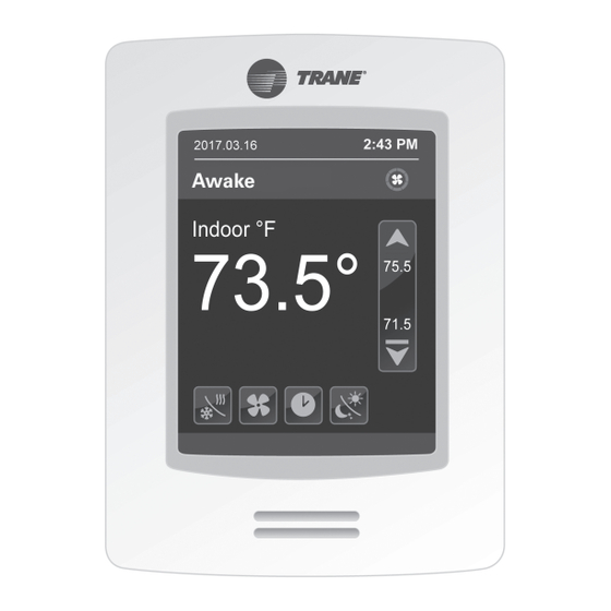
General Information The sensor displays Power on during initial power-up and advances to display the Home Screen. All user accessible functions are easily set from the Home screen: Occupancy Fan Status Status Increment Up Cooling Setpoint Temperature Heating Setpoint Increment Down Fan Mode Schedule Menu Heat/Cool Mode... -
Page 8: Configuring Settings On The Home Screen
Configuring Settings on the Home Screen Cool/Heat Mode • Off: the system will not cool or heat the space. • Auto: the system switches between cooling and heating automatically to condition the space. • Cool: the system will only provide cooling to the space. •... -
Page 9: Interface Flowcharts
Interface Flowcharts User Menus Touch the Schedule Menu button on the display to setup, Clock, Schedule, Setpoints, Vacation, and Options. BAS-SVN026G-EN... -
Page 10: Clock, Schedule, Setpoints, Display, Vacation, And Options
Interface Flowcharts Clock, Schedule, Setpoints, Display, Vacation, and Options Configures the following: • Time format: configured as either AM-PM (displays as 8:00 PM) or 24 Hours (displays as 20:00). • Time: displays according to the time format. • Year: set the year. Clock •... -
Page 11: Installer Menus
Interface Flowcharts Installer Menus Note: The Installer password is 4017 and cannot be changed. BAS-SVN026G-EN... -
Page 12: Configuring The Sensor
BACnet address of the UC400/UC400-B (range of 0-127). Sets the baud rate. Default is 76800 (leave default value unless directed Baud rate by Trane Technical Support). This setting is not configurable. It indicates that BACnet communication Status is occurring between the UC400/UC400-B and the sensor. -
Page 13: Service View
Configuring the Sensor Service View • Firmware rev.: firmware installed on sensor. • Room temp.: measured room temperature. • Effective occ.: schedule mode setting. 1/2 Service View • Effective temp.: temperature sensor in use. • Unit status: current communication state between the wall display and the equipment controller. -
Page 14: Specifications
Specifications Sensor Operating 32°F to 122°F (0°C to 50°C) Temperature Storage –22°F to 122°F (–30°C to 50°C) Temperature Storage and Operating 0% to 95%, non-condensing Humidity Range Temperature +/- 0.9°F (+/– 0.5°C) @ 70F (21°C) typical calibrated Control Accuracy Temperature +/–... - Page 15 Specifications WARNING Cancer and Reproductive Harm! This product can expose you to chemicals including lead and bisphenol A (BPA), which are known to the State of California to cause cancer and birth defects or other reproductive harm. For more information, go to www.P65Warnings.ca.gov BAS-SVN026G-EN...
- Page 16 For more information, please visit trane.com or tranetechnologies.com. Trane has a policy of continuous product and product data improvement and reserves the right to change design and specifications without notice. We are committed to using environmentally conscious print practices.
Need help?
Do you have a question about the Tracer UC400 and is the answer not in the manual?
Questions and answers