Table of Contents
Advertisement
Quick Links
Advertisement
Table of Contents

Related Manuals for AMX AXB-F117 Stealth 1


Summary of Contents for AMX AXB-F117 Stealth 1
- Page 1 $;%0)44: 6WHDOWK 4 &DPHUD &RQWUROOHU ,QVWUXFWLRQ 0DQXDO &DPHUD &RQWURO 6\VWHPV...
- Page 2 AMX dealer. Consumers should inquire from selling dealer as to the nature and extent of the dealer’s warranty, if any. AMX is not liable for any damages caused by its products or for the failure of its products to perform, including any lost profits, lost savings, incidental damages, or consequential damages.
-
Page 3: Table Of Contents
Wiring guidelines Using the AXlink 4-pin connector Using the lens control DB-15 HD (high density) connector Using the camera control RS-232 DB-9 connector Setting the adjustable pan-limit stops Setting the adjustable tilt-limit stops AXB-F117 Stealth 1 Camera Controller Table of Contents... - Page 4 Preset functions Levels Send_Commands Preset parameters and commands Downloading preset commands Uploading preset commands RS-232 commands RS-232 Send_Strings Stand-Alone RS-232 Protocol Response mask Specifications ..............52 Overview Technical Support ............... 54 Overview Table of Contents AXB-F117 Stealth 1 Camera Controller...
-
Page 5: Introduction
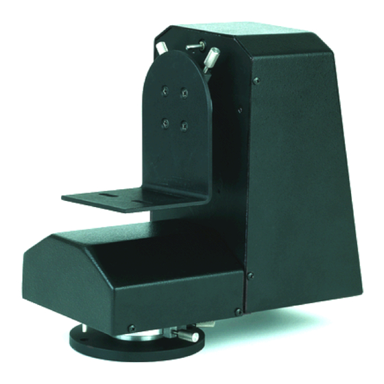
Introduction Overview The AXB-F117 Stealth 1 Camera Controller (Figure 1) is a camera and lens controller that can be used for a wide variety of precision camera-positioning applications. The AXB-F117 supports both AXlink and RS-232 control protocols. The integrated AXB-F117 camera controller connects directly to the AMX AXlink control network and includes onboard intelligence for consistent motion and lens control. -
Page 6: What's New
Revised Pre-Installation section with new circuit card control mode switches, and lens control voltage switch. Added configuration settings for lens control mode and lens control voltage switchers (for units that have switchers rather than jumpers). Introduction AXB-F117 Stealth 1 Camera Controller... -
Page 7: Application
The most common servomotor mode is positional mode. In this mode, the lens moves when the voltage changes and remains at that position until the voltage changes again. For example, if a lens receives a voltage of +3 VDC, the lens moves to the AXB-F117 Stealth 1 Camera Controller Introduction... -
Page 8: Speed Mode
POT outputs. These outputs are sent to the AXB-F117, and when that level matches the level stored in the preset, the lens returns to the center point. Motor- mode lenses that do not have POT outputs do not have preset recall capability. Introduction AXB-F117 Stealth 1 Camera Controller... -
Page 9: Pre-Installation Settings
Figure 3 shows the DIP switches and lens control jumpers accessible on the back panel. Figure 3 DIP switches and control mode/voltage jumpers AXlink RS-232 VOLT 1 2 3 4 5 6 7 8 ZOOM FOCUS 1 2 3 4 5 6 7 8 IRIS DEVICE AXB-F117 Stealth 1 Camera Controller Pre-Installation Settings... -
Page 10: Setting Zoom, Focus, And Iris Jumpers To Servomotor Or Motor Mode
Figure 5 shows the DIP switches and lens control switches accessible on the back panel. Figure 5 AXlink DIP switches and control mode/voltage switches RS-232 VOLT 1 2 3 4 5 6 7 8 ZOOM FOCUS 1 2 3 4 5 6 7 8 IRIS DEVICE Pre-Installation Settings AXB-F117 Stealth 1 Camera Controller... -
Page 11: Setting Zoom, Focus, And Iris Switches To Servomotor Or Motor Mode
5 set the parity, and positions 6 through 8 set the baud rate. Figure 7 shows the RS-232 DIP switch and Figure 8 lists their settings. Figure 7 RS-232 RS-232 communications 1 2 3 4 5 6 7 8 parameters DIP switch (S1) AXB-F117 Stealth 1 Camera Controller Pre-Installation Settings... -
Page 12: Setting The Axlink Device Dip Switch (S2)
Figure 9 1 2 3 4 5 6 7 8 AXlink Device DIP switch DEVICE (S2) example Figure 10 Device DIP switch (S2) settings Position Device DIP switch (S2) positions and values Value Pre-Installation Settings AXB-F117 Stealth 1 Camera Controller... -
Page 13: Setting Internal Jumpers To Axlink Or Rs-232 Communication Mode
Carefully pull the back panel away from the main unit far enough to lay the back panel down on a flat surface, and locate the E5, E6, and E7 communication mode jumpers (Figure 12). AXB-F117 Stealth 1 Camera Controller Pre-Installation Settings... - Page 14 Set jumpers E5, E6, and E7 for RS-232 communication mode (Figure 14). Then, go to step 7. Figure 14 RS232 E5, E6, and E7 jumper settings for RS-232 AXLINK communication mode Pre-Installation Settings AXB-F117 Stealth 1 Camera Controller...
- Page 15 Make sure the cables are not pinched in the back panel or drive gears. The communication settings Insert the four pan-head screws and tighten. for RS-232 mode are: 9,600 baud No parity 8 bits 1 stop bit AXB-F117 Stealth 1 Camera Controller Pre-Installation Settings...
- Page 16 Pre-Installation Settings AXB-F117 Stealth 1 Camera Controller...
-
Page 17: Installation
(55.8 mm) 7.90 To mount the AXB-F117: Select a surface that can support the combined weight of the AXB-F117 (6.7 lb/3.0 kg), camera, lens, and control cables. Determine the center of rotation for pan/tilt: AXB-F117 Stealth 1 Camera Controller Installation... - Page 18 Figure 17. Secure the AXB-F117 to the surface using four 1/4" x 20 machine bolts and lock washers. If you want to mount the AXB-F117 to a wall, go to step 4. Otherwise, go to step 5. Installation AXB-F117 Stealth 1 Camera Controller...
- Page 19 WM-CAM to the wall, and secure the AXB-F117 to the WM-CAM’s mounting plate using four 1/2" (1/4" x 20) machine bolts and lock washers. Figure 19 shows a side view of the WM-CAM. AXB-F117 Stealth 1 Camera Controller Installation...
- Page 20 (127.0 mm) Figure 19 1.0" Wall mounting plate Pan/tilt mounting plate (25.4 mm) WM-CAM Wall Mount kit dimensions (side view) 3.0" (25.4mm) 18.0" (457.2 mm) Mount and balance the camera and lens on the AXB-F117. Installation AXB-F117 Stealth 1 Camera Controller...
-
Page 21: Wiring The Connectors
Do not over-torque the screws; doing so can bend Turn the flat-head screws clockwise to secure the wire in the connector. the seating pin and damage the connector. AXB-F117 Stealth 1 Camera Controller Installation... -
Page 22: Wiring Guidelines
Note The AXB-F117 requires 12 VDC power to operate properly. The power can be supplied by the AMX Control System’s AXlink cable or with an optional 12 VDC The AXB-F117 power rating power supply. The maximum wiring distance between the control system and is 6 amps @ 12 VDC. - Page 23 PWR terminal on the AXB-F117 when you connect Use the local 12 VDC power supply when the distance between the AMX Control an external power supply. System and AXB-F117 exceeds the limits listed in Figure 21. Make sure to connect only the GND wire on the AXlink/RS-232 connector when using a local 12 VDC power supply.
-
Page 24: Using The Lens Control Db-15 Hd (High Density) Connector
Figure 26 lists the pinouts for motor-mode lenses, and Figure 27 lists the appropriate lens pinouts for servomotor-mode camera lenses. manufacturer. Figure 25 Pin 5 Pin 1 Lens control DB-15 HD Pin 10 connector (female) wiring Pin 6 pinouts Pin 15 Pin 11 Installation AXB-F117 Stealth 1 Camera Controller... - Page 25 VREF—A (+7.5 V). The reference voltage must be present to operate correctly in servomotor mode. VREF—B (+2.5 V) Input VREF—B (+2.5 V). The reference voltage must be present to operate correctly in servomotor mode. AXB-F117 Stealth 1 Camera Controller Installation...
-
Page 26: Using The Camera Control Rs-232
If you are not sure about the motor type, refer to the Technical Support section and contact AMX Corporation for assistance. Using the camera control RS-232 DB-9 connector Connect the AXB-F117 RS-232 DB-9 (male) connector to the camera head’s RS-232... - Page 27 The click indicates the pan-limit switch is engaged. Tighten the right adjustable pan-limit stop. Pan to both stop positions and ensure the pan-limit stops are set correctly. Then, make sure both adjustable pan-limit stops are properly tightened. AXB-F117 Stealth 1 Camera Controller Installation...
-
Page 28: Setting The Adjustable Tilt-Limit Stops
Then, repeat step 4 to set the left adjustable tilt-limit stop. Tilt to both stop positions and ensure the tilt-limit stops are set correctly. Then, make sure both adjustable tilt-limit stops are properly tightened. Installation AXB-F117 Stealth 1 Camera Controller... -
Page 29: Replacing The Lithium Battery
Figure 31. Figure 31 Grasp the battery on each side near the bottom of the Lithium battery and holder holder. Then, pull it out of the holder. AXB-F117 Stealth 1 Camera Controller Replacing the Lithium Battery... - Page 30 Uploading preset commands sections for details. according to the manufacturer’s instructions. Never recharge, disassemble, or heat the battery above 212°F (100°C). Never solder directly to the battery or expose the contents of the battery to water. Replacing the Lithium Battery AXB-F117 Stealth 1 Camera Controller...
-
Page 31: Axcess Programming
Focus (servomotor; positional) The AXB-F117 is controlled with device-specific channel settings and AXCESS Send_Commands. You create the software programs with the AMX AXCESS programming software. Use the programming information in this section along with the AXCESS Programming Guide to create a program to control the AXB-F117. - Page 32 M position (motor mode) setting on the IRIS switch. 'IRIS SIGNAL=S' Set the Iris output to be a servomotor output. This setting corresponds to the S position (servomotor mode) setting on the IRIS switch. AXCESS Programming AXB-F117 Stealth 1 Camera Controller...
- Page 33 FOCUS switch. 'READ ALL' Force the device to read and update levels to the Central Controller. 'ZAP!' Initialize all memory to default settings. This includes speed settings, deviation settings, configuration settings, and all presets. AXB-F117 Stealth 1 Camera Controller AXCESS Programming...
-
Page 34: Channel Commands
Zoom + at current speed (increases output voltage) lens functions Zoom - at current speed (decreases output voltage) Focus + at current speed Focus - at current speed Iris + at current speed Iris - at current speed AXCESS Programming AXB-F117 Stealth 1 Camera Controller... -
Page 35: Channel Commands For Servomotor Speed Mode Lens Functions
Iris - at current speed Zoom + at maximum speed Zoom - at maximum speed Focus + at maximum speed Focus - at maximum speed Iris + at maximum speed Iris - at maximum speed AXB-F117 Stealth 1 Camera Controller AXCESS Programming... -
Page 36: Preset Functions
Recall preset 2—128 or currently at preset 2-128. Levels Figure 38 lists levels used in programming the AXB-F117. Figure 38 Levels AXCESS Level Levels Tilt Zoom Focus Pan POT Tilt POT Zoom POT Focus POT AXCESS Programming AXB-F117 Stealth 1 Camera Controller... -
Page 37: Send_Commands
Set the current speed for future and current Send_Commands and channel commands. This command can be used for motor-mode and servomotor speed-mode applications. Example: SEND_COMMAND CAM,'G1S64' Sets PAN to speed 64 (50%) for current and future commands. AXB-F117 Stealth 1 Camera Controller AXCESS Programming... - Page 38 POT input as a reference. This command can be used for motor-mode and servomotor speed-mode applications. Example: SEND_COMMAND CAM,'G1L32000' Sets PAN to search for position 32000 as referenced by the PAN POT input. AXCESS Programming AXB-F117 Stealth 1 Camera Controller...
- Page 39 'GxLxxx' commands. This command can be used for motor-mode and servomotor speed-mode applications. Example: SEND_COMMAND CAM,'G1A5520' Sets PAN to speed 20 when within 5 of the specified position for future 'GxLxxx' commands. AXB-F117 Stealth 1 Camera Controller AXCESS Programming...
- Page 40 "down to up" only. This command can be used for motor-mode and servomotor positional-mode applications. Example: SEND_COMMAND CAM,'P5R25D' Sets iris ramp rate to 2.5 seconds full range for “up to down” only. AXCESS Programming AXB-F117 Stealth 1 Camera Controller...
- Page 41 (Added v1.10) Example: SEND_COMMAND CAM,'TILT CURVE=INVERT’ Sets the tilt curve to inverted, for inverted installation position. Note: This does not reverse the direction of the pan/tilt motors. AXB-F117 Stealth 1 Camera Controller AXCESS Programming...
-
Page 42: Preset Parameters And Commands
A 0 setting disables the preset timer function. The default setting is 5. time = 0-100. Example: SEND_COMMAND CAM,'PRESET TIMER=10' Sets preset timer to 1 second. AXCESS Programming AXB-F117 Stealth 1 Camera Controller... - Page 43 POTs. Pan/tilt outputs will use current speed. Turns on channel 110. AXB-F117 Stealth 1 Camera Controller AXCESS Programming...
- Page 44 (64). Pan/tilt outputs will use current speed. Turns on channel 110. 'SP<preset 1-255>’ Store preset. Example: SEND_COMMAND CAM,'SP1' Stores current values to Preset 1. AXCESS Programming AXB-F117 Stealth 1 Camera Controller...
-
Page 45: Downloading Preset Commands
Tilt level low Zoom defined Zoom level high Zoom level low Focus defined Focus level high Focus level low Pan POT defined Pan POT level high Pan POT level low Tilt POT defined AXB-F117 Stealth 1 Camera Controller AXCESS Programming... -
Page 46: Uploading Preset Commands
31 bytes long. The string is the following form: “’GP’,preset number,preset structure” Example: SEND_COMMAND CAM,'GP1' Uploads Preset 1 values from the AXB-F117. Get Preset Return String Structure Position Byte Value Preset number Pan level low AXCESS Programming AXB-F117 Stealth 1 Camera Controller... - Page 47 Tilt Pot level low Zoom Pot defined Zoom Pot level high Zoom Pot level low Focus Pot defined Focus Pot level high Focus Pot level low Iris defined Iris level high Iris level low Iris mode AXB-F117 Stealth 1 Camera Controller AXCESS Programming...
-
Page 48: Rs-232 Commands
Enable pushes and releases and status on channel 255 for CTS hardware handshake input. If CTS is high, then channel is on. Example: SEND_COMMAND CAM,'CTSPSH' Enables pushes, releases, and status information on channel 255 for CTS hardware handshake input. AXCESS Programming AXB-F117 Stealth 1 Camera Controller... - Page 49 Central Controller. This command is automatically sent by the master when a 'CREATE_BUFFER' program instruction is executed. Example: SEND_COMMAND CAM,'RXON' Enables the device to send incoming (received) characters to the Central Controller. AXB-F117 Stealth 1 Camera Controller AXCESS Programming...
-
Page 50: Rs-232 Send_Strings
Set the ninth bit to 1 for all subsequent characters to be transmitted. Used in conjunction with the 'B9MON' command. "27,19,<time>" Insert a delay before the next character to be transmitted. time = 1 - 255 in 1 millisecond increments AXCESS Programming AXB-F117 Stealth 1 Camera Controller... -
Page 51: Stand-Alone Rs-232 Protocol
General format Byte No. Attention Byte Command # Data Last Checksum, sum of all bytes Mod 256 Note RS-232 Levels Level Valid <LEVEL NO> are 0 - 7. TILT ZOOM FOCUS PAN_POT TILT_POT AXB-F117 Stealth 1 Camera Controller AXCESS Programming... - Page 52 '*' <9> <CHECKSUM> '*' <10> <MASK1> <MASK2> <CHECKSUM> Set response mask '*' <11> <0> <CHECKSUM> Send all on channels '*' <12> <0> <CHECKSUM> Send all levels '*' <13> <0> <LEVEL Set level (word) NO><LEVEL_H><LEVEL_L><CHECKSUM> AXCESS Programming AXB-F117 Stealth 1 Camera Controller...
-
Page 53: Response Mask
Data is automatically sent if the AXB-F117 receives a change request. The response mask should be disabled if the change request data is not used. Bits in the response mask (Figure 50) turns data off. (1=ON) DATA SENT (0=OFF) DATA NOT SENT AXB-F117 Stealth 1 Camera Controller AXCESS Programming... - Page 54 CHANNEL CHANGE LEVEL CHANGE Note BUS LED Bus LED change defaults to (future) off. (future) 0 (lsb) (future) Second byte (MASK2) 7 (msb) (future) (future) (future) (future) (future) (future) (future) 0 (lsb) (future) AXCESS Programming AXB-F117 Stealth 1 Camera Controller...
-
Page 55: Specifications
Figure 52 Specifications Specifications Angular travel 150° Tilt 45° Speed 24°/sec Tilt 11°/sec Torque (maximum) AXB-F117 2 ft-lb Tilt AXB-F117 6 ft-lb Weight capacity AXB-F117 10 lb (4.5 kg) balanced lens/camera weight (maximum) AXB-F117 Stealth 1 Camera Controller Specifications... -
Page 56: Specifications
DB-15 HD 15-pin high-density (female) for lens control DB-9 9-pin D-sub (male) for RS-232 camera control Options PS6.3 power supply CC-CAM lens control cable (specify make and model) CC-CAM RS-232 camera control cable (specify make and model) WM-CAM Wall Mount kit Specifications AXB-F117 Stealth 1 Camera Controller... -
Page 57: Overview
Technical Support Overview Prior to calling AMX for assistance, check your AXlink, power, and cable connections, and the integrity of your software operating system. Reload the software to see if something in the program is causing the problem. If the problem is not resolved, reload the program from a new copy of your master disk. - Page 58 11995 Forestgate Drive 048-004-1555 6/98 ©1998 AMX Corporation. All rights reserved. Dallas, Texas USA 75243 AMX and the AMX logo are registered trademarks of AMX Corporation. All other 972/644-3048 800/222-0193 trademarks contained in this document are the properties of their respective Fax 972/907-2053 www.amx.com...
Need help?
Do you have a question about the AXB-F117 Stealth 1 and is the answer not in the manual?
Questions and answers