
Related Manuals for AMX AXB-TCTCR TELEVISION CONTROLLERRECEIVER


Summary of Contents for AMX AXB-TCTCR TELEVISION CONTROLLERRECEIVER
-
Page 1: Instruction Manual
instruction manual AXB-TC and AXB-TCR Television Controllers A X l i n k B u s C o n t r o l l e r s... - Page 2 RMA number. AMX Corporation is not liable for any damages caused by its products or for the failure of its products to perform. This includes any lost profits, lost savings, incidental damages, or consequential damages. AMX Corporation is not liable for any claim made by a third party or by an AMX Dealer for a third party.
-
Page 3: Table Of Contents
Table of Contents Table of Contents Product Information ....................1 Specifications ........................2 Applications ........................3 Installation and Wiring .....................5 Setting the Device DIP Switch................... 5 Internal Jumper Settings ....................5 JI jumper settings: TV power sensing/TV power current sensing mode ........6 J2 jumper settings: IR output mode (IR or serial communication) ........... - Page 4 Table of Contents AXB-TC and AXB-TCR Television Controllers...
-
Page 5: Product Information
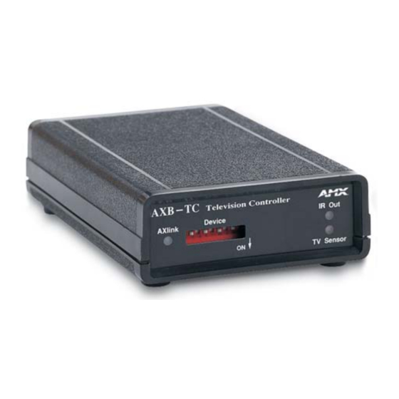
Product Information Product Information The AXB-TC and AXB-TCR Television Controllers are intelligent, microprocessor-controlled systems equipped with a lithium battery to protect stored memory. The television controllers can control a variety of Infrared-controlled devices such as televisions, audio receivers, and videocassette recorders. FIG. -
Page 6: Specifications
8-position DIP switch that sets the AXlink device number on the AXB-TC and AXB-TCR. IR Input Window (AXB-TCR only) Receives 38 kHz IR-control signals from AMX transmitters. The IR input window contains a red LED that lights when receiving IR- control data. -
Page 7: Applications
Product Information AXB-TC/TCR Specifications (Cont.) Mounting options: Flat surface Included accessories: • CC-IR TV Sensor (CC-XPS sensor) • CC-IRC IR Emitter Optional accessories: • SE-TC Security Enclosure • PCS Power Current Sensor • VSS2 Video Sync Sensor • 12 VDC Power supply Applications FIG. - Page 8 Product Information AXB-TC and AXB-TCR Television Controllers...
-
Page 9: Installation And Wiring
Installation and Wiring Installation and Wiring Setting the Device DIP Switch The eight-position Device DIP switch sets the identification number for the television controller. Make sure the device number matches the number assigned in the AXCESS software program. The quick reference table below shows the switch positions and their numeric value. In the example below, the numeric value of the Device DIP switch is 97 (1+32+64=97). -
Page 10: Ji Jumper Settings: Tv Power Sensing/Tv Power Current Sensing Mode
Installation and Wiring 4. Replace the top portion of the enclosure on the bottom portion. Then, refasten the two Phillips- head screws. JI jumper settings: TV power sensing/TV power current sensing mode JI Jumper Settings: TV Power Sensing/TV Power Current Sensing Television Power (on or off) Sensing mode To use this mode, connect a CC-IRC to the television to detect horizontal scan frequen-... -
Page 11: Wiring
Installation and Wiring Wiring The TV sensor, IR emitter, AXlink, and 12 VDC power supply connectors are located on the rear panel of the television controller as shown in FIG. 1 on page 1. Do not connect power directly to the television controller. If you are using power from AXlink, disconnect the wiring from the Central Controller before connecting the wiring to the television controller. -
Page 12: Ir Emitter Connections
Installation and Wiring IR Emitter connections Connect the CC-IRC IR Emitter to the IR Emitter connector, on the rear panel of the television controller (FIG. 5) to transmit IR control signals to the television. CC-IRC Television IR EMITTER connector FIG. 5 CC-IRC IR Emitter connector wiring diagram Axlink data and power connections Connect the Central Controllers's AXlink connector to the AXlink connector on the rear panel of the television controller for data and 12 VDC power, as shown in FIG. -
Page 13: Pcs And Axlink Data And Power Connections
Installation and Wiring Use the 12 VDC power supply when the distance between the AMX system and television controller exceeds the limits described in the Wiring Guidelines table on page 7. Make sure to connect only the GND wire on the AXlink connector when using a 12 VDC power supply. -
Page 14: Installation
Installation and Wiring Installation Install the television controller on any flat surface or inside the optional SE-TC Security Enclosure, as described below: 1. Mount the Axcess Central Controller where it will be used. Then, connect the power supply. 2. Route the Axlink power and data cable, CC-IR TV Sensor cable, CC-IRC IR Emitter cable, and 12 VDC power supply from the television to the television controller's location. -
Page 15: Television Power Sensor Adjustment
Installation and Wiring Television Power Sensor Adjustment After connecting the CC-IR to the television, the power sensing POT, on the rear of the television controller (see FIG. 1 on page 1), may require adjustment to detect the television's power status: Use a Phillips-head screwdriver and flat-blade tool (non-conducting) to adjust the POT screw. -
Page 16: Replacing The Lithium Battery
All control commands in television controller memory are lost when the lithium battery is replaced. Contact your AMX dealer before you replace the lithium battery to verify that they have a current copy of the IRLIB program file for your television controller. This will prevent any inadvertent loss of data or service outage. - Page 17 Installation and Wiring 6. Carefully pry the battery out of its socket and insert the new battery. Write down the next replacement date on a label by adding 5 years to the replacement date; attach it to the bottom of the television controller.
- Page 18 Installation and Wiring AXB-TC and AXB-TCR Television Controllers...
-
Page 19: Programming Information
Programming Information The television controllers are controlled with channel settings, IR functions, and Axcess Send_Commands. You create software programs with the AMX Axcess programming software. Use the programming information in this section with the Axcess Programming Guide to program television controllers. After you create the IRLIB program, download it to the non-volatile (battery protected) memory in the television controller. -
Page 20: Ir Functions (Standard Order)
Programming Information IR Functions (Standard Order) The following table lists the IR function, in their standard order. IR Functions (Standard Order) Function Description Function Description play > channel up or + stop [] channel down or - pause | | or still volume up or + ffwd >>... -
Page 21: Send_Commands
Programming Information Send_Commands Use the Send_Commands listed in the following table to program the Axcess Central Controller and television controller. The device number range for the television controller is 1 through 255. Refer to the Axcess Programming Language instruction manual for additional programming information. - Page 22 Programming Information Send_Commands (Cont.) ?CTON Sends the current on-time pulse string "'CTON',<Time>" to the master. Set the <Time> value in .10 second increments. Example: SEND_COMMAND 92,'?CTON' Sends the current on-time pulse string from device 92 to the master. 'DC',<IR in>,<IR out> Sets a direct connection so the <IR out>...
- Page 23 Programming Information Send_Commands (Cont.) 'PTOF',<Time> Sets the IR power-off pulse time after a power-on pulse in increments of .10 seconds. Time is stored in permanent memory. Variable: <Time> = 0-255; System default = 15 (1.5 seconds). Example: SEND_COMMAND 55,"'PTOF',15" Sets the power-off pulse time after a power-on pulse to 1.5 seconds for device 55.
- Page 24 Programming Information Send_Commands (Cont.) XCHM Syntax: Changes the IR output pattern for SEND_COMMAND <DEV>,'XCH-<Mode>' the XCH command. Variable: Mode = 0-4 Example: SEND_COMMAND IR_1,'XCH 3' Sets the IR_1 device's extended channel command to mode 3. Mode 0 Example (default): [x] [x] <x> <enter> SEND_COMMAND IR_1, 'XCH 3' Transmits the IR code as 3-enter.
-
Page 25: Firmware Upgrades
(RS-232) interface connecting to the AXlink DB-9 programming port input. There are two ways to upgrade the firmware to an Axcess device: via the DOS-based SOFTROM application, or via the NetLinx Studio program. Both are included on the AMX Software Control Disc. -
Page 26: Using Netlinx Studio
Programming Information F2 can be pressed to select all ONLINE PANEL devices and F3 can be pressed to clear all devices. 5. Press F4 to program the selected device(s), the loading status bar in FIG. 14 then appears. 6. Press F5 to refresh the screen. Verify that all selected panels have the correct firmware version. If any devices still indicated the old version, repeat preceding steps 3 through 5 until all panels indicate the correct firmware version. - Page 27 Programming Information 3. Click Browse to navigate to the directory containing the firmware file(s). Once a directory containing one or more .TSK files is specified, a list of available .TSK files is displayed in the upper table in this dialog. 4.
- Page 28 ATLANTA • BOSTON • CHICAGO • CLEVELAND • DALLAS • DENVER • INDIANAPOLIS • LOS ANGELES • MINNEAPOLIS • PHILADELPHIA • PHOENIX • PORTLAND • SPOKANE • TAMPA 3000 RESEARCH DRIVE, RICHARDSON, TX 75082 USA • 800.222.0193 • 469.624.8000 • 469-624-7153 fax • 800.932.6993 technical support • www.amx.com...
Need help?
Do you have a question about the AXB-TCTCR TELEVISION CONTROLLERRECEIVER and is the answer not in the manual?
Questions and answers