Table of Contents
Advertisement
Quick Links
Advertisement
Table of Contents

Subscribe to Our Youtube Channel
Related Manuals for IMC Networks iMcV-10G-Converter XFP/XFP


Summary of Contents for IMC Networks iMcV-10G-Converter XFP/XFP
- Page 1 iMcV-10G-Converter XFP/XFP Operation Manual...
-
Page 2: Fcc Radio Frequency Interference Statement
At its option, IMC Networks will repair or replace at no charge the product which proves to be defective within such warranty period. This limited warranty shall not apply if the IMC Networks product has been damaged by unreasonable use, accident, negligence, service or modification by anyone other than an authorized IMC Networks Service Technician or by any other causes unrelated to defective materials or workmanship. -
Page 3: Table Of Contents
Table of Contents FCC Radio Frequency Interference Statement ............ii Warranty......................ii About the iMcV-10G-Converter XFP/XFP ............1 Configuration Instructions ..................1 Installing an iMcV-Modules ................1 Managed Modules .....................2 Configuration Control and SNMP Management..........2 LED Operation....................7 Specifications .....................8 IMC Networks Technical Support...............9 Fiber Optic Cleaning Guidelines...............10 Electrostatic Discharge Precautions..............11... -
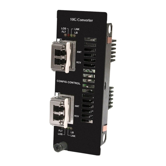
Page 4: About The Imcv-10G-Converter Xfp/Xfp
Single Mode (SM) and Multi Mode (MM). The supported transmission speeds are: 10G Ethernet, 10G Sonet/SDH, 10G Fiber channel and 10G OTN. The copper SFP supports 10G Ethernet only. For information about the iMcV-10G-Converter refer to the IMC Networks web site http://www.imcnetworks.com/Support/Downloads.cfm Configuration Instructions The iMcV-10G-Converter modules have user-configurable features (e.g., Loss Carry... -
Page 5: Managed Modules
Managed Modules To manage one or more iMcV-Modules, a SNMP Management Module must be installed in an iMediaChassis series, available in 3, 6 or 20 slots for both AC and DC. Using management, the 10G converter will be identified in the slot it is installed in, as well as options to set LoopBack and Loss Carry Forward (LCF). - Page 6 Configuration Control had three goals when it was created: Any type of module or Management Module, could be swapped out under power with out losing any configuration. The Management Module can be added to a chassis without losing any configuration. The Management Module should not be subjected to failure or interruption in a “Mission Critical”...
- Page 7 Inserting a Management Module Without Configuration Control • Modules in an unmanaged chassis use DIP Switch settings. When the Management Module is inserted, the modules use the configuration stored in the Management Module. This will more then likely change the configuration of the modules, and will cause a short interruption in data flowing through the modules.
-
Page 8: Unmanaged Modules
Unmanaged Modules Before installing, configure the iMcV-10G-Converter modules for desired features. The DIP Switch settings enable the end user to select the speed/protocol, loopback modes and Loss Carry Forward (LCF). The table below indicates the available features and settings for the iMcV-10G-Converter modules. Switch Function Default... - Page 9 Loss Carry Forward (LCF) When a fault is detected on the incoming optical line that would severely affect the quality of the corresponding output optical signal, this signal is turned OFF as opposed to sending a bad optical signal to the next unit over the optical line. The Loss Carry Forward function provides a very positive fault indication to the downstream unit.
-
Page 10: Led Operation
LED Operation Each iMcV-10G-Converter features diagnostic LEDs that provide information on features and ports. Name Color Function Yellow ON When a DDMI fault is detected ON when the Optical LINK is good Green ON when no link is detected Yellow ON when Loopback is enabled and “Blinks”... -
Page 11: Specifications
Specifications Power Consumption (Typical @ 5V): 637mA @ +70C Operating Temperature -4°F to +158°F (-20°C to +70°C) Storage Temperature -40°F to +185°F (-40°C to +85°C) Humidity 5 to 95% (non-condensing); 0 to 10,000 ft. altitude Dimensions Dual-wide iMcV-module... -
Page 12: Imc Networks Technical Support
IMC Networks Technical Support Tel: (949) 465-3000 or (800) 624-1070 (in the U.S. and Canada); +32-16-550880 (Europe) Fax: (949) 465-3020 E-Mail: techsupport@imcnetworks.com Web: www.imcnetworks.com... -
Page 13: Fiber Optic Cleaning Guidelines
Dust caps are installed at IMC Networks to ensure factory-clean optical devices. These protective caps should not be removed until the moment of connecting the fiber cable to the device. Should it be necessary to disconnect the fiber device, reinstall the protective dust caps. -
Page 14: Electrostatic Discharge Precautions
Electrostatic Discharge Precautions Electrostatic discharge (ESD) can cause damage to any product, add-in modules or stand alone units, containing electronic components. Always observe the following precautions when installing or handling these kinds of products Do not remove unit from its protective packaging until ready to install. Wear an ESD wrist grounding strap before handling any module or component. -
Page 15: Safety Certifications
Certifications The products described herein comply with the Council Directive on Electromagnetic Compatibility (2004/108/EC) For further details, contact IMC Networks. Class 1 Laser product, Luokan 1 Laserlaite, Laser Klasse 1, Appareil A’Laser de Classe 1 European Directive 2002/96/EC (WEEE) requires that any equipment that bears this symbol on product or packaging must not be disposed of with unsorted municipal waste. - Page 16 The information in this document is subject to change without notice. IMC Networks assumes no responsibility for any errors that may appear in this document. iMcV-10G-Converter XFP/XFP is a trademark of IMC Networks. Other brands or product names may be trademarks and are the property of their respective companies.
Need help?
Do you have a question about the iMcV-10G-Converter XFP/XFP and is the answer not in the manual?
Questions and answers