Table of Contents
Advertisement
HEAT & COOL MODEL
(REVERSE CYCLE)
ROOM AIR CONDITIONER
FLOOR TYPE
KEEP THIS OPERATION MANUAL
FOR FUTURE REFERENCE
FUJITSU GENERAL LIMITED
07J353_9316796003-01_cover.p65
1
OPERATING MANUAL
R410A
REFRIGERANT
This Air Conditioner contains and operates
with refrigerant R410A and Polyol Ester oil.
THIS PRODUCT MUST ONLY BE INSTALLED OR SERVICED
BY QUALIFIED PERSONNEL.
Refer to Commonwealth, State, Territory and local legislation,
regulations, codes, installation & operation manuals, before
the installation, maintenance and/or service of this product.
2007.09.25, 19:32
P/N9316796003-01
Advertisement
Table of Contents

Related Manuals for Fujitsu Inverter 9316796003-01


Summary of Contents for Fujitsu Inverter 9316796003-01
-
Page 1: Operating Manual
BY QUALIFIED PERSONNEL. Refer to Commonwealth, State, Territory and local legislation, regulations, codes, installation & operation manuals, before KEEP THIS OPERATION MANUAL the installation, maintenance and/or service of this product. FOR FUTURE REFERENCE FUJITSU GENERAL LIMITED P/N9316796003-01 07J353_9316796003-01_cover.p65 2007.09.25, 19:32... -
Page 2: Table Of Contents
CONTENTS SAFETY PRECAUTIONS .......... 1 AIR OUTLET SELECTION ........11 FEATURES AND FUNCTIONS ......... 2 10°C HEAT OPERATION ......... 12 NAME OF PARTS ............4 ECONOMY OPERATION ......... 12 PREPARATION ............5 SWING OPERATION ..........13 OPERATION .............. 6 COIL DRY OPERATION ........... 13 TIMER OPERATION .......... -
Page 3: Features And Functions
FEATURES AND FUNCTIONS INVERTER SWING OPERATION At the start of operation, a large power is used to bring the The Air Flow Direction Louvers swings automatically up and room quickly to the desired temperature. Afterwards, the down so that the air speeds to every nook and corner of unit automatically switches to a low power setting for eco- your room. - Page 4 Fig. 1 Fig. 2 TIMER OPERATION 10˚c HEAT Fig. 3 Fig. 4 Fig. 5 MODE MODE 10˚c HEAT 10˚c HEAT ECONOMY ECONOMY SWING Fig. 6 To facilitate explanation, the accompanying illustra- tion has been drawn to show all possible indicators; in actral operation, however, the display will only show those indicators appropriate to the current op- eration.
-
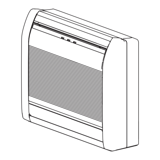
Page 5: Name Of Parts
NAME OF PARTS Fig. 1 Indoor Unit Fig. 5 Remote Control Unit 1 Operating Control Panel (Fig. 2) H SLEEP button 2 Air Outlet Selection switch I MODE button 3 MANUAL AUTO button J 10°C HEAT button ● K SET TEMP. button ( When kept on pressing the MANUAL AUTO button for more than 10 seconds, L COIL DRY button... -
Page 6: Preparation
PREPARATION Load Batteries (R03/LR03 × × × × × 2) CAUTION! ● Take care to prevent infants from accidentally swallowing batteries. Press and slide the battery compartment lid on the re- ● When not using the Remote Control Unit verse side to open it. for an extended period, remove the batteries to avoid possible leakage and Slide in the direction of the arrow while pressing the... -
Page 7: Operation
OPERATION To Select Mode Operation Press the START/STOP button (Fig.5 R). The indoor unit’s OPERATION Indicator Lamp (green) (Fig. 3 6) will light. The air conditioner will start operating. Press the MODE button (Fig.5 I) to select the desired mode. Each time the button is pressed, the mode will change in the following order. - Page 8 To Stop Operation Press the START/STOP button (Fig. 5 R). The OPERATION Indicator Lamp (green) (Fig. 3 6) will go out. About AUTO CHANGEOVER Operation ● When AUTO CHANGEOVER operation first selected, the fan will oper- AUTO: ate at very low speed for about one minute, during which time the unit detects the room conditions and selects the proper operating mode.
-
Page 9: Timer Operation
TIMER OPERATION Before using the timer function, be sure that the Remote Control Unit is set to the correct current time (☞ P. 5). To Use the ON timer or OFF timer Press the START/STOP button (Fig. 5 R) To Cancel the Timer (if the unit is already operating, proceed to step 2). -
Page 10: Sleep Timer Operation
SLEEP TIMER OPERATION Unlike other timer functions, the SLEEP timer is used to set the length of time until air conditioner operate is stopped. To Use the SLEEP Timer To Cancel the Timer: While the air conditioner is operating or stopped, press the Use the TIMER MODE button to select SLEEP button (Fig. -
Page 11: Adjusting The Direction Of Air Circulation
ADJUSTING THE DIRECTION OF AIR CIRCULATION Vertical (up-down) direction of airflow is adjusted by pressing the Remote Control Unit’s SET button. Horizontal (right-left) airflow direction is adjusted manually, by moving the Air Flow Direction Louvers. Whenever making horizontal airflow adjustments, start air conditioner operation and be sure that the vertical air direction louvers are stopped. -
Page 12: Air Outlet Selection
AIR OUTLET SELECTION With this function , air come out simultaneously from the upper and lower air outlets so that the room can be cooled or heated effectively. This function is set using the switch behind the front grille of the Indoor unit. (This function is available in cooling and heating operation.) How to set to blow out air from the upper and lower air outlets ■... -
Page 13: 10°C Heat Operation
10°C HEAT OPERATION • The room temperature can be maintained at 10°C by pressing the 10°C HEAT button (Fig.5 J) so as to prevent the room temperature from falling too far. To use 10°C HEAT OPERATION While 10˚C HEAT OPERATION is in progress, the following operations/ features cannot be used Press the 10°C HEAT button (Fig.5 J) -
Page 14: Swing Operation
SWING OPERATION Begin air conditioner operation before performing this procedure. To select SWING Operation Press the SWING button (Fig. 5 T). The SWING Display (Fig. 6 d) will light. In this mode, the Air Flow Direction Louvers will swing automatically to direct the air flow both up and down. -
Page 15: Cleaning And Care
CLEANING AND CARE ● Before cleaning the air conditioner, be sure to turn it off. CAUTION! ● Be sure the Intake Grille (Fig. 1 9) is installed securely. ● When removing and replacing the air filter, be sure not to touch the heat exchanger, as personal injury may result. - Page 16 CLEANING AND CARE Air Cleaning Filter Installation Replacing dirty Air cleaning filters Replace filters with the following components (purchased 1. Open the Intake Grille and remove the Air separately). filter. ● POLYPHENOL CATECHIN AIR CLEANING FILTER : UTR-FC03-2 ● Negative air ions deodorizing filter: UTR-FC03-3 1.
-
Page 17: Troubleshooting
TROUBLESHOOTING In the event of a malfunction (burning smell, etc.), immediately stop operation, turn off the elec- WARNING! trical breaker or disconnect the power supply plug, and consult authorized service personnel. Merely turning off the unit’s power switch will not completely disconnect the unit from the power source. - Page 18 TROUBLESHOOTING Symptom Problem See Page ● The damper is automatically controlled by a microcomputer ac- NORMAL The damper opens and FUNCTION closes automatically cording to the air flow temperature and operation time of the air — conditioner. See Page Items to check Symptom ●...
-
Page 19: Operating Tips
OPERATING TIPS Operation and Performance Microcomputer-controlled Automatic Defrosting Heating Performance ● When using the Heating mode under conditions of low ● This air conditioner operates on the heat-pump princi- outdoor temperature and high humidity, frost may form ple, absorbing heat from outdoor air and transferring that on the outdoor unit, resulting in reduced operating per- heat indoors.
Need help?
Do you have a question about the Inverter 9316796003-01 and is the answer not in the manual?
Questions and answers