Table of Contents
Advertisement
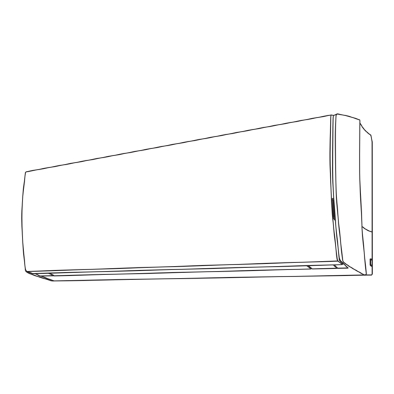
AIR CONDITIONER
INDOOR UNIT
Compact Wall Mounted Type
INSTALLATION MANUAL
INSTALLATION MANUAL
For authorized service personnel only.
INSTALLATIONSANLEITUNG
Nur für autorisiertes Personal.
MANUEL D'INSTALLATION
Pour le personnel agréé uniquement.
MANUAL DE INSTALACIÓN
Solo para personal autorizado.
MANUALE D'INSTALLAZIONE
Ad uso esclusivo del personale autorizzato.
MANUAL DE INSTALAÇÃO
Apenas para técnicos autorizados.
KURULUM KILAVUZU
Yetkili servis personeli içindir.
PART NO. 9319357003-02
Advertisement
Table of Contents

Related Manuals for Fujitsu 9319357003-02


Summary of Contents for Fujitsu 9319357003-02
-
Page 1: Installation Manual
Nur für autorisiertes Personal. MANUEL D'INSTALLATION Pour le personnel agréé uniquement. MANUAL DE INSTALACIÓN Solo para personal autorizado. MANUALE D'INSTALLAZIONE Ad uso esclusivo del personale autorizzato. MANUAL DE INSTALAÇÃO Apenas para técnicos autorizados. KURULUM KILAVUZU Yetkili servis personeli içindir. PART NO. 9319357003-02... -
Page 2: Table Of Contents
The unit must be correctly grounded and the supply line must be equipped with a dif- Compact Wall Mounted Type ferential breaker in order to protect the persons. PART NO. 9319357003-02 The units are not explosion proof and therefore should not be installed in explosive atmosphere. -
Page 3: General Specification
2.5. Optional parts 2.3. For authorized service personnel only. Refer to each installation manual for the method of installing optional parts. WARNING Parts name Model No. Application Wired remote controller * UTY-RNN M For air conditioner operation For the air conditioner to operate satisfactorily, install it as outlined in this installation Simple remote controller * UTY-RSN M For air conditioner operation... -
Page 4: Selecting The Mounting Position
5. SELECTING THE MOUNTING POSITION 6.2. Indoor unit piping direction The piping can be connected in the 6 directions indicated in the following. Decide the mounting position with the customer as follows: When the piping is connected in direction (2) , (3) , (4) or (5) , cut along the piping groove in the side of the under cover with a hacksaw. - Page 5 6.6. Cutting the hole in the wall for the connecting piping CAUTION Insert drain hose and drain cap securely. Drain should slope down to avoid water (1) Cut a 65 mm diameter hole in the wall at the position shown in the following. leakage.
- Page 6 [Installing the indoor unit] Width across flats Width across Pipe outside diameter [mm (in.)] • Hang the indoor unit from the hooks at the top of the wall hook bracket. of Flare nut [mm] flats • Insert the spacer, etc. between the indoor unit and the wall hook bracket and separate 6.35 (1/4) the bottom of the indoor unit from the wall.
-
Page 7: Electrical Wiring
7. ELECTRICAL WIRING 7.3. How to connect wiring to the terminals Caution when wiring cable Cable Cable size (mm Type Remarks Connection cable Type 60245 IEC57 3Cable+Ground, 1φ230V When stripping off the insulation of a lead wire, always use a special tool such as a wire stripper. -
Page 8: Finishing
8. FINISHING 9. FRONT PANEL REMOVAL AND INSTALLATION (1) Insulate between pipes. • Insulate suction and discharge pipes separately. 9.1. Intake grille removal • For rear, right, and bottom piping, overlap the connection pipe heat insulation and indoor unit pipe heat insulation and bind them with vinyl tape so that there is no (1) Open the intake grille. -
Page 9: Test Run
[Using the wired remote controller] (Option) 9.4. Front panel installation For the operation method, refer to the operating manual. (1) Stop the air conditioner operation. (1) First, fi t the lower part of the front panel, and insert top and bottom hooks. (2 top (2) Press the MODE button and the FAN button simultaneously for sides, 7 bottom sides, 2 center) 2 seconds or more to start the test run. - Page 10 12.2.3. Installing relay control board and relay wire terminal 12.1. Accessories (Communication kit) The following installation accessories are supplied. Use them as required. Control unit board Name and Shape Q’ty Description Connector (CN8) Relay control board For connecting the wired remote control Relay wire unit and external connect wire.
-
Page 11: Selecting The Remote Controller Signal Code
Installing the external connect kit terminal (sold separately) 14. FUNCTION SETTING Connect the wire of external input/output to the board of external connect kit. Perform the “FUNCTION SETTING” according to the installation conditions using the EXTERNAL INPUT CONNECT TO NO. CNA01 EXTERNAL OUTPUT CONNECT TO NO. -
Page 12: Customer Guidance
Heating Room Temperature Correction 15. CUSTOMER GUIDANCE Depending on the installed environment, the room temperature sensor may require a cor- rection. Explain the following to the customer in accordance with the operating manual: The settings may be changed as shown in the table below. (1) Starting and stopping method, operation switching, temperature adjustment, timer, air fl... - Page 13 • 2-way valve temp. sensor error ● ● ◊ • 3-way valve temp. sensor error Heat sink temp. sensor error ● ● ◊ • Sub-cool Heat Ex. gas inlet temp. sensor error ● ● ◊ • Sub-cool Heat Ex. gas outlet temp.
Need help?
Do you have a question about the 9319357003-02 and is the answer not in the manual?
Questions and answers