Extron electronics Digital Video Transmitter and Receiver HDMI 201 Tx/Rx User Manual
Digital video transmitter and receiver
Hide thumbs
Also See for Digital Video Transmitter and Receiver HDMI 201 Tx/Rx:
- User manual (23 pages)
Table of Contents
Advertisement
Quick Links
Extron Electronics, USA
Extron Electronics, Europe
1230 South Lewis Street
Beeldschermweg 6C
Anaheim, CA 92805
3821 AH Amersfoort, The Netherlands
800.633.9876 714.491.1500
+800.3987.6673 +31.33.453.4040
FAX 714.491.1517
FAX +31.33.453.4050
www.extron.com
© 2008 Extron Electronics. All rights reserved.
Extron Electronics, Asia
Extron Electronics, Japan
135 Joo Seng Rd. #04-01
Kyodo Building, 16 Ichibancho
PM Industrial Bldg., Singapore 368363
Chiyoda-ku, Tokyo 102-0082
+800.7339.8766 +65.6383.4400
Japan
FAX +65.6383.4664
+81.3.3511.7655 FAX +81.3.3511.7656
User's Manual
Digital Video Transmitter and Receiver
HDMI 201 Tx/Rx
68-1375-01 Rev. A
01 08
Advertisement
Table of Contents

Related Manuals for Extron electronics Digital Video Transmitter and Receiver HDMI 201 Tx/Rx


Summary of Contents for Extron electronics Digital Video Transmitter and Receiver HDMI 201 Tx/Rx
- Page 1 Extron Electronics, USA Extron Electronics, Europe Extron Electronics, Asia 1230 South Lewis Street Beeldschermweg 6C 135 Joo Seng Rd. #04-01 Anaheim, CA 92805 3821 AH Amersfoort, The Netherlands PM Industrial Bldg., Singapore 368363 800.633.9876 714.491.1500 +800.3987.6673 +31.33.453.4040 +800.7339.8766 +65.6383.4400 FAX 714.491.1517 FAX +31.33.453.4050 FAX +65.6383.4664 www.extron.com...
- Page 2 Precautions Safety Instructions • English Warning Power sources • This equipment should be operated only from the power source This symbol is intended to alert the user of important indicated on the product. This equipment is intended to be used with a main power operating and maintenance (servicing) instructions in system with a grounded (neutral) conductor.
-
Page 3: Fcc Class A Notice
安全须知 • 中文 这个符号提示用户该设备用户手册中 有重要的操作和维护说明。 这个符号警告用户该设备机壳内有暴 露的危险电压,有触电危险。 注意 阅读说明书 • 用 户 使 用 该 设 备 前 必 须 阅 读 并 理 解 所 有 安 全 和 使 用 说 明 。 保存说明书 • 用户应保存安全说明书以备将来使 用。 遵守警告 • 用户应遵守产品和用户指南上的所有安 全和操作说明。... -
Page 4: Table Of Contents
Table of Contents Chapter One • Introduction ... 1-1 About this Manual ... 1-2 About the HDMI 201 Tx/Rx ... 1-2 TP cable advantages... 1-4 Control communications... 1-4 Transmission distance..1-4 Features ... 1-5 Chapter Two • Installation and Operation Mounting the Tx/Rx ... - Page 5 Table of Contents, cont’d Appendix A • Reference Information Specifications ...A-2 Part Numbers ...A-6 Transmitter/receiver pair part numbers ...A-6 Included parts ...A-6 Mounting accessories ...A-7 Cables ...A-7 Adapters ...A-8 Decora Template Dimensions ...A-8 All trademarks mentioned in this manual are the properties of their respective owners. HDMI 201 Tx/Rx • Table of Contents .
-
Page 6: About This Manual
Introduction About this Manual This manual contains information about the Extron family of High Definition Multimedia Interface (HDMI HDMI 201 Tx/Rx transmitter and receiver pair, including how to install, operate, and configure them. In this manual, the term "Tx/Rx" refers to either product. About the HDMI 201 Tx/Rx The Extron HDMI 201 Tx/Rx is a family of HDMI transmitters and receivers, in enclosures that support different mounting options. -
Page 7: Tp Cable Advantages
Introduction, cont’d In this manual, the terms "HDMI 201," "HDMI 201 Tx," "HDMI 201 Rx," "transmitter," and "receiver" refer to the applicable unit(s) in either form factor, unless otherwise specified. TP cable advantages Twisted pair cable is much smaller, lighter, more flexible, and less expensive than coaxial or HDMI cable. These transmitter and receiver twisted pair (TP) products make cable runs simpler and less cumbersome. Termination of the cable with RJ-45 connectors is simple, quick, and economical. - Page 8 Introduction, cont’d HDMI 201 Tx/Rx Chapter Two Installation and Operation Mounting.the.Tx/Rx Connections Operation Technical.Points.for.Digital.Video.and.Content.Protection.Encryption Troubleshooting Application.Examples HDMI 201 Tx/Rx • Introduction...
-
Page 9: Mounting The Tx/Rx
Installation and Operation Mounting the Tx/Rx Installation and service must be performed by authorized personnel only. Non-Decora unit mounting The 1" high, quarter rack width HDMI 201 (non-Decora) transmitters and receivers can be placed on a tabletop, mounted on a rack shelf, or mounted under a desk or tabletop. The receiver can be mounted on a projector bracket. -
Page 10: Under-Furniture Mounting
Installation and Operation, cont’d 1U Universal Rack Shelf 1/2 Rack Width Front False Faceplate Both front false faceplates use 2 screws. Use 2 mounting holes on opposite corners. Figure 2-2 — Mounting the transmitter or receiver unit on a standard rack shelf Under-furniture mounting The unit can be mounted under a horizontal surface using an optional MBU 125 under-desk mounting kit (part #70-077-01). -
Page 11: Projector Mounting
Installation and Operation, cont’d Loosely attach the mounting brackets to the transmitter or receiver using the four machine screws and washers supplied with the mounting kit. Hold the transmitter or receiver against the inside of the surface through which it will be mounted. Mark the four screw holes on the inside of the surface to which you are mounting the device. - Page 12 Installation and Operation, cont’d The PMK 300 has a hole in the bottom plate that allows the projector pole to be inserted through the center of the plate (figure 2-6), rather than outside of the plate (figure 2-5). To install the PMK 300 in this configuration, slide the bracket up from the bottom of the pole before the projector is installed on the pole. Bracket Brace Extron U-Bolt PMK 300 Multi-product Projector Mount Kit Figure 2-6 — Projector pole on the inside Place the contoured bracket brace against the pole and opposite the back plate. The pole should fit snugly into the depression in the center of the bracket brace.
-
Page 13: Decora Unit Mounting
Installation and Operation, cont’d Assemble the U-bolt and the following parts in the following order (figure 2-8): a. Pass the legs of the U-bolt through the slotted holes on the mount plate flange. b. Place the legs around the projector pole. c. - Page 14 Installation and Operation, cont’d 2.50 [63.5mm] TP Cable 1.51 [38.48mm] (no boot) Captive Screw Connectors TP Cable (no boot) Junction Box 1.85 [47mm] Figure 2-9 — Decora unit depth profile To install a new wall box, perform steps 1 through 9 below. If a suitable wall box is already installed, perform steps 6 through 9 below.
-
Page 15: Final Installation
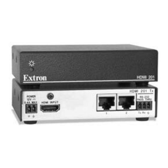
Installation and Operation, cont’d Final installation After testing and making any adjustments, do the following: At the power outlet, unplug the power supply. One power supply can power both the transmitter and the receiver, so only one unit needs a power supply. Mount the transmitter or receiver into the wall box, and attach the supplied Decora faceplate to the unit, as shown in figure 2-11. - Page 16 Installation and Operation, cont’d HDMI 201 Tx Rear Panel POWER HDMI INPUT 0.4A MAX HDMI 201 A D Tx Rear Panel HDMI 201 A D Tx DO NOT CONNECT TO LAN Figure 2-13 — HDMI 201 Tx rear panel connectors The RS-232 connector can also transmit one-way modulated infrared (IR) signals. See "Modulated IR pass through" on page 2-32.
-
Page 17: Receiver Connections
Installation and Operation, cont’d Audio Output connector (HDMI 201 A D Tx [Decora] only) — Connect one end of a 5-wire audio cable to this 3.5 mm, 5-pole direct insertion connector. Connect the free end of the same cable from the transmitter to any compatibly wired unit, such as a switcher, an amplifier, or an HDMI 201 A D Rx (Decora) receiver. - Page 18 Installation and Operation, cont’d HDMI 201 A D Rx Front Panel OUTPUT HDMI AUDIO-R RS-232 PASS THRU AUDIO-L Figure 2-17 — HDMI 201 A D Rx front panel connectors DC power input connector — Plug the included external 12 VDC power supply into either this 2-pole connector or the power input connector on the transmitter (item See "Power supply wiring,"...
-
Page 19: Pin Assignments And Wiring
Installation and Operation, cont’d Output Audio — Plug an audio device into this pair, left and right, of female RCA connectors (figure 2-14) for an unbalanced stereo audio signal. Pin assignments and wiring HDMI connector pin assignments Figure 2-19 defines the pinout for the HDMI protocol. HDMI Type A Receptacle Signal... -
Page 20: Power Supply Wiring
Installation and Operation, cont’d Terminating shielded cable The transmitter and receiver pair works with unshielded twisted pair (UTP) or shielded twisted pair (STP) cables; but, to ensure FCC Class A and CE compliance, STP cables are recommended. The Tx/Rx includes four shielded RJ-45 connectors and a length of self-adhesive shielded tape that you can use to make the STP cables that connect the transmitter and receiver. Extron supplies the connectors and the shielded tape. -
Page 21: Rs-232 Connector Wiring
Installation and Operation, cont’d The two power cord wires must be kept separate while the power supply is plugged in. Remove power before wiring. The length of the exposed (stripped) copper wires is important. The ideal length is 3/16" (5 mm). Longer bare wires can short together. Shorter wires are not as secure in the connector and could be pulled out. Do not tin the power supply leads before installing in the direct insertion connector. Tinned wires are not as secure in the connectors and could be pulled out of the connector. Non-Decora units only — Use the supplied tie-wrap to strap the power cord to the extended tail of the connector. Your transmitter/receiver pair may have shipped with a blue captive screw connector. This blue connector can be plugged into either a blue or an orange power receptacle. -
Page 22: Transmitter Power Indicator
Installation and Operation, cont’d Transmitter power indicator Power LED — HDMI 201 Tx (non-Decora) — This front panel LED lights green to indicate that the unit is receiving power: HDMI 201 A D Tx (Decora) — This two-color front panel LED lights to indicate signal and power status as follows: Amber — The unit is receiving power. Green —... -
Page 23: Troubleshooting
Installation and Operation, cont’d Troubleshooting HDMI signals run at a very high frequency and are especially susceptible to bad video connections, too many adapters, or cables that are too long. To avoid the loss of an image or introduction of image jitter, follow these guidelines: •... -
Page 24: Specifications
Installation and Operation, cont’d Modulated IR pass through Figure 2-28 shows an installation in which the Tx/Rx pair sends a modulated infrared (IR) signal across the link. On the Tx side, control system is connected to the Tx pin (the modulated IR signal) and the Gnd (signal ground) on the transmitter. -
Page 25: Specifications
Reference Information Specifications This product consists of a transmitter (HDMI 201 TX or HDMI 201 D TX) and a receiver (HDMI 201 RX or HDMI 201 A D RX) with twisted pair cables linking the transmitter and receiver. Video input (TX units) Number/signal type ... 1 single link HDMI input Connectors ... 1 HDMI female Interconnection between transmitter and receiver Connectors ... 2 RJ-45 per unit for 2 CAT 5/5e/6 or STP (shielded twisted pair) cables connecting the transmitter and receiver Termination standards... - Page 26 Reference Information, cont’d Maximum level (Hi-Z) HDMI 201 A D TX ... >11.4 dBu, balanced or unbalanced at 1% THD+N HDMI 201 A D RX ... >5.3 dBu, unbalanced at 1% THD+N Maximum level (600 ohm) HDMI 201 A D TX ... >5.1 dBm, balanced or unbalanced at 1% THD+N HDMI 201 A D RX ...
-
Page 27: Transmitter/Receiver Pair Part Numbers
Reference Information, cont’d MTBF ... 30,000 hours Warranty ... 3 years parts and labor All nominal levels are at ±10%. Specifications are subject to change without notice. Part Numbers Transmitter/receiver pair part numbers The Tx/Rx is comprised of the transmitter/receiver pair. The transmitter and receiver cannot be purchased separately. HDMI 201 models HDMI 201 Tx/Rx (non-Decora) HDMI 201 Tx HDMI 201 Rx HDMI 201 A D Tx/Rx (Decora) black, white HDMI 201 A D Tx black, white HDMI 201 A D Rx black, white Included parts... -
Page 28: Decora Template Dimensions
Reference Information, cont’d Adapters Accessories HDMIF-DVIDM HDMI female to DVI-D male adapter HDMIM-DVIDF HDMI male to DVI-D female adapter Decora Template Dimensions If you need to create a template, use the dimensions shown on figure A-1, below. 4.50" (11.43 cm) Figure A-1 —...
Need help?
Do you have a question about the Digital Video Transmitter and Receiver HDMI 201 Tx/Rx and is the answer not in the manual?
Questions and answers